Caution: Refer to Brake Fluid Irritant Caution in the Preface section.
Notice: Refer to Brake Fluid Effects on Paint and Electrical Components Notice in the Preface section.
Notice: Hydraulic brake systems use two distinct and incompatible fluids. Power steering fluid is used in the hydraulic brake booster system. Brake fluid is used in the master cylinder and brake pipes. Use extreme care when selecting brake system fluids, or seal damage can result. Refer to General Information to select the correct fluid.
Checking and Adding Fluid
For information on checking and adding fluid to the power brake booster system, refer to Checking and Adding Power Steering Fluid.
Bleeding the Power Brake Booster System
For information on bleeding the power brake booster system, refer to Power Steering System Bleeding.
Flushing the Power Brake Booster System
For information on flushing the power brake booster system, refer to Power Steering System Flushing.
Removal Procedure
- Apply the park brake and block the wheels.
- Without disconnecting the brake pipes, remove the master cylinder and support with heavy mechanics wire or equivalent. Refer to Master Cylinder Replacement.
- Disconnect the power brake booster inlet hose fitting (1).
- Disconnect the power brake booster outlet hose fitting (1).
- Remove the power brake booster pushrod retaining clip (1).
- Disconnect the stoplamp switch electrical connector.
- Disconnect the power brake booster pushrod and remove the stoplamp switch (1).
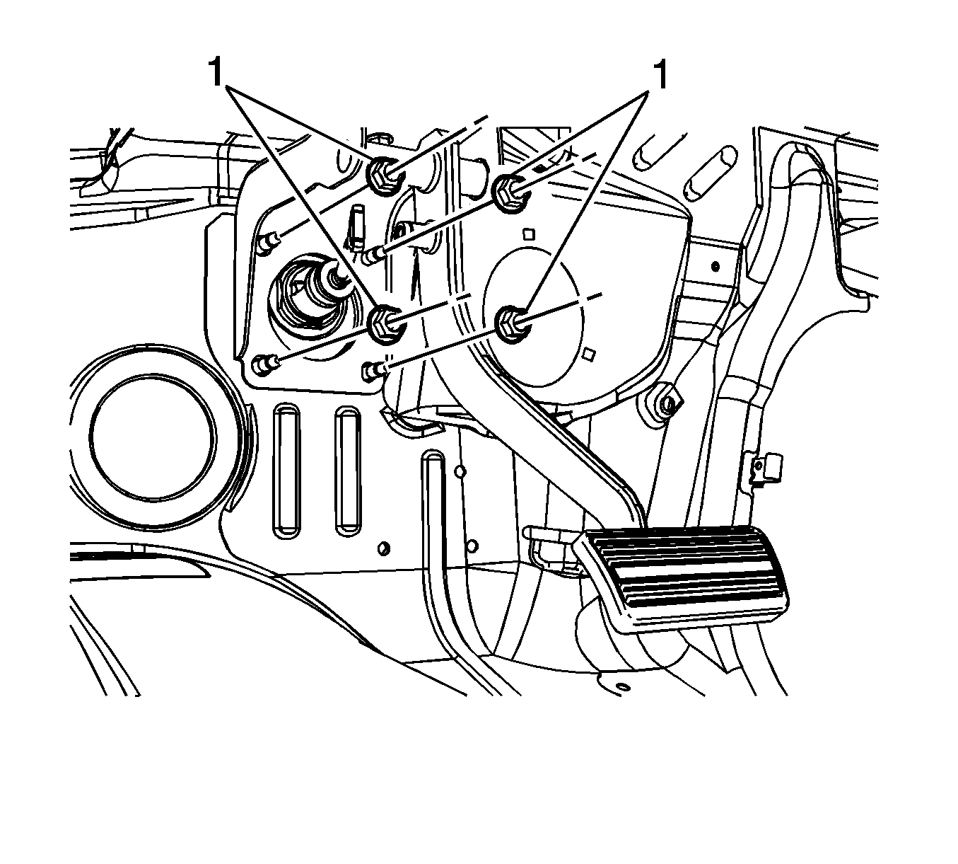
- Remove the power brake booster nuts (1).
- Remove the power brake booster.
- Remove the power brake booster gasket.
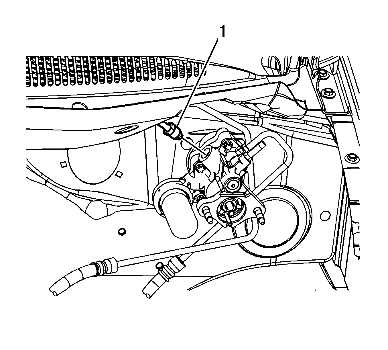
Inspect the O-ring seal for damage and replace, if necessary.
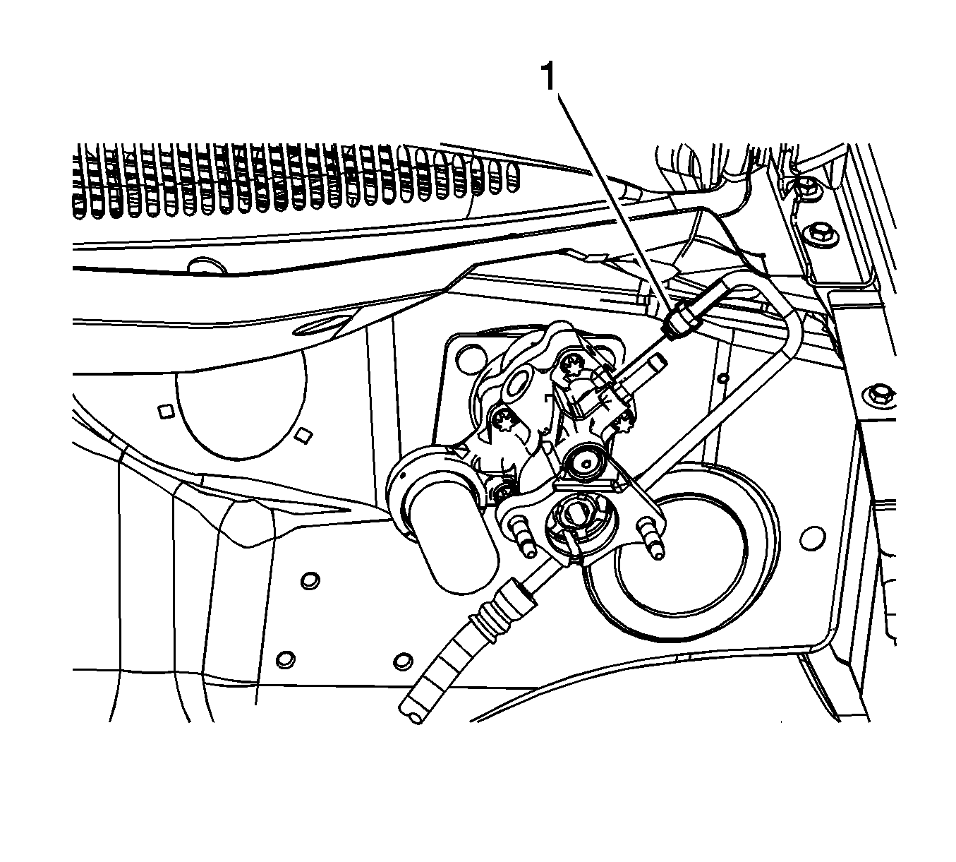
Inspect the O-ring seal for damage and replace, if necessary.
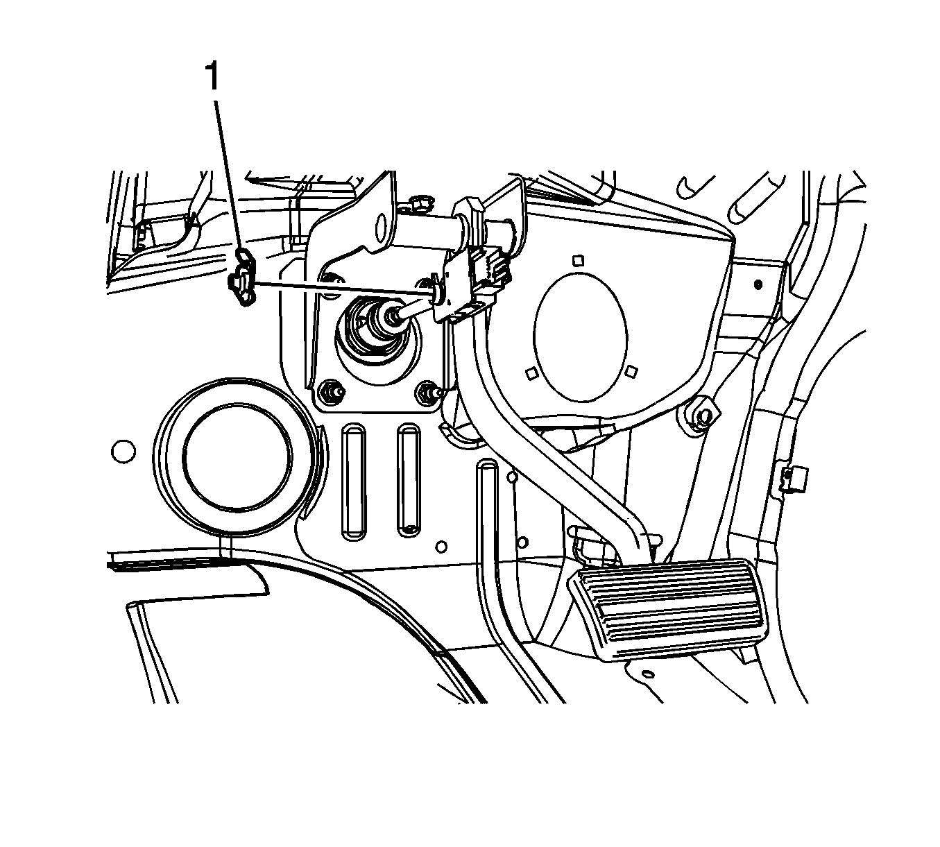
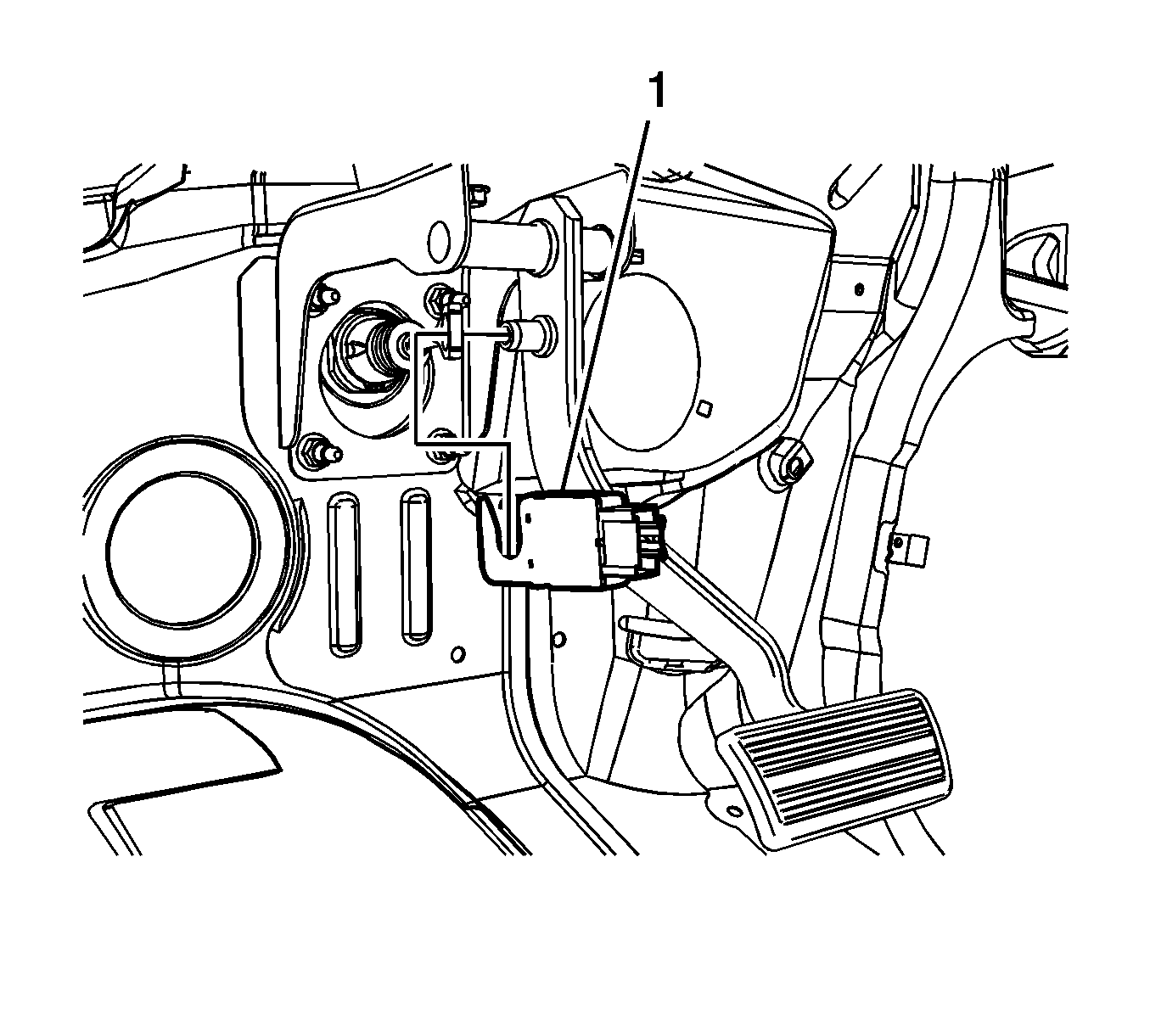
Inspect the power brake booster gasket for damage and replace, if necessary.
Installation Procedure
- Install the power brake booster gasket.
- Install the power brake booster.
- Install the power brake booster nuts (1).
- Apply a thin coat of high temperature lubricant, GM P/N 12345994 (Canadian P/N 10953501) to the brake pedal pivot pin.
- Install the stoplamp switch (1) and simultaneously connect the power brake booster pushrod.
- Connect the stoplamp switch electrical connector.
- Install the power brake booster pushrod retaining clip (1).
- Rotate the power brake booster retaining clip 360 degrees to ensure the clip is fully engaged in the brake pedal pivot pin groove.
- Connect the power brake booster outlet hose fitting (1).
- Connect the power brake booster inlet hose fitting (1).
- Install the master cylinder. Refer to Master Cylinder Replacement.
- Bleed the power steering system. Refer to Power Steering System Bleeding.

Notice: Refer to Fastener Notice in the Preface section.
Tighten
Tighten the nuts to 36 N·m (27 lb ft).


Important: Ensure the O-ring seals are properly positioned on the power brake booster inlet and outlet hose fittings.

Tighten
Tighten the fitting to 33 N·m (24 lb ft).

Tighten
Tighten the fitting to 33 N·m (24 lb ft).
