Removal Procedure
- Disable the SIR system. Refer to SIR Disabling and Enabling in SIR.
- Remove the upper and lower trim covers. Refer to Steering Column Trim Covers Replacement .
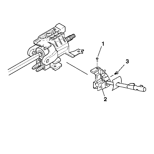
- Disconnect the connector to the turn signal and multifunction switch assembly (2).
- Remove the 2 pan head tapping screws (1) and (3) from the turn signal and multifunction switch assembly (2).
- Remove the turn signal and multifunction switch assembly (2) from the steering column tilt head assembly.

Caution: This vehicle is equipped with a Supplemental Inflatable Restraint (SIR) System. Failure to follow the correct procedure could cause the following conditions:
• Air bag deployment • Personal injury • Unnecessary SIR system repairs • Refer to SIR Component Views in order to determine if you are performing service on or near the SIR components or the SIR wiring. • If you are performing service on or near the SIR components or the SIR wiring, disable the SIR system. Refer to Disabling the SIR System.
Installation Procedure
- Install the turn signal and multifunction switch assembly (2).
- Screw the 2 pan head tapping screws (1) and (3) into the turn signal and multifunction assembly (2).
- Connect the connector to the turn signal and multifunction switch assembly.
- Install the upper and lower trim covers. Refer to Steering Column Trim Covers Replacement .
- Enable the SIR system. Refer to SIR Disabling and Enabling in SIR.

Notice: Refer to Fastener Notice in the Preface section.
Important: Be sure that the electrical contact of the turn signal and multifunction switch assembly (2) rests on the turn signal cancel cam assembly.
Tighten
| • | Tighten the top pan head tapping screw (1) to 3 N·m (30 lb in). |
| • | Tighten the side pan head tapping screw (3) to 7 N·m (62 lb in). |
