For 1990-2009 cars only
Removal Procedure
- Disable the SIR system. Refer to SIR Disabling and Enabling .
- Remove the right knee bolster bracket. Refer to Passenger Knee Bolster Bracket Replacement in Instrument Panel, Gages and Console.
- Remove the passenger instrument panel (I/P) trim pad. Refer to Instrument Panel Trim Pad Replacement in Instrument Panel, Gages and Console.
- Remove the body control module. Refer to Body Control Module Replacement in Computer/Integrating Systems.
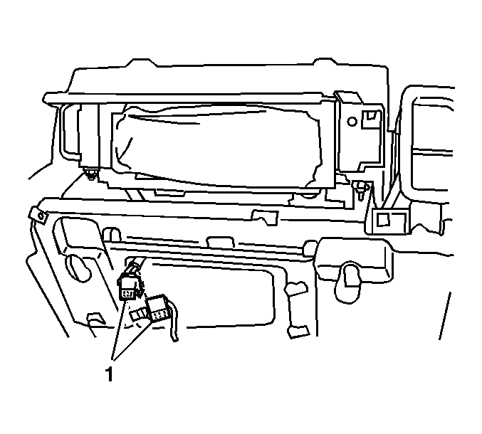
- Remove the connector position assurance (CPA) from the harness connector on the inflatable restraint I/P module.
- Disconnect the I/P module electrical connector (1).
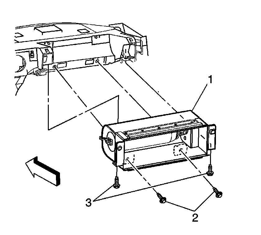
- Remove the upper bolts (3) from the I/P module (1).
- Remove the lower bolts (2) from the I/P module (1).
- Remove the I/P module (1).
- Ensure that the I/P module is fully deployed before disposal. If the module was replaced under warranty, fully deploy and dispose of the module after the required retention period. Refer to Inflator Module Handling and Scrapping .
Caution: Refer to SIR Inflator Module Handling and Storage Caution in the Preface section.
Caution: Refer to SIR Caution in the Preface section.


Installation Procedure
- Install the inflatable restraint I/P module (1) to the I/P carrier.
- Install the lower bolts (2) hand tight.
- Install the lower bolts (3) to the inflatable restraint I/P module.
- Install the right knee bolster bracket. Refer to Passenger Knee Bolster Bracket Replacement in Instrument Panel, Gages and Console.
- Install the passenger I/P trim pad. Refer to Instrument Panel Trim Pad Replacement in Instrument Panel, Gages and Console.
- Connect the electrical connector (1) to the inflatable restraint I/P module.
- Install the CPA to the I/P module electrical connector.
- Install the body control module. Refer to Body Control Module Replacement in Computer/Integrating Systems.
- Enable the SIR system. Refer to SIR Disabling and Enabling .

Notice: Refer to Fastener Notice in the Preface section.
Tighten
Tighten the bolts to 10 N·m (89 lb in).

