Removal Procedure
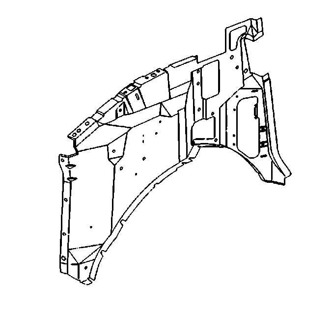
Important: The front inner fender may be serviced as a complete component. However, replacement at the factory seams requires the removal of the outer door frame panel. If the damage is limited to the front portion of the inner fender, sectioning is recommended.
Caution: Refer to Approved Equipment for Collision Repair Caution in the Preface section.
- Disable the SIR system. Refer to SIR Disabling and Enabling .
- Disconnect the negative battery cable. Refer to Battery Negative Cable Disconnection and Connection .
- Remove all related panels and components.
- Visually inspect and repair as much of the damage as possible to factory specification.
- Note the location and remove the sealers and anti-corrosion materials from the repair area, as necessary. Refer to Anti-Corrosion Treatment and Repair .
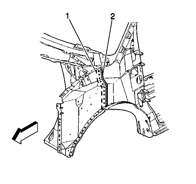
- The sectioning procedure is to be performed at the door frame opening forward attachment seam (1).
- Cut the original inner fender at the front edge of the seam (1).
- Locate, mark and drill out factory spot welds attaching the inner fender to the wheelhouse and radiator support brace. Note the number and location of the welds for installation of the service panel.
- Remove the damaged section of the front inner fender.
Caution: Refer to Foam Sound Deadeners Caution in the Preface section.
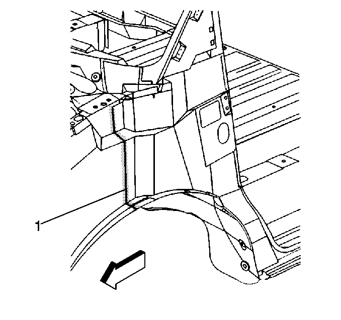
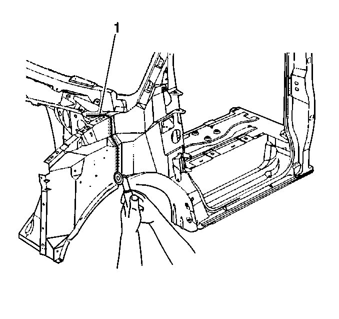
Important: Do not damage any inner panels or reinforcements.
Installation Procedure
- The service inner fender must be cut to overlap the door frame opening 25 mm (1 in).
- Temporarily position the service part over the door frame weld flange (2).
- At the hood hinge mounting area (1), the service part must be installed under the upper cowl panel and over the door frame opening weld flange (2).
- Inspect for proper fit and alignment. Make sure there is a flush fit at the door frame weld flange.
- Remove the service part and drill 8 mm (5/16 in) holes for plug welding as noted from the original panel and along the sectioning (1) joint 13 mm (½ in) from the cut edge.
- Install and position the modified service part according to body dimensions using three-dimensional measuring equipment.
- Apply GM-approved weld-thru coating or equivalent to all mating surfaces. Refer to Anti-Corrosion Treatment and Repair .
- Plug weld accordingly.
- Use frequent measurements to ensure accurate fit and alignment to adjacent panels.
- Clean and prepare all welded surfaces.
- Apply the sealers and anti-corrosion materials to the repair area, as necessary. Refer to Anti-Corrosion Treatment and Repair .
- Paint and repair the area. Refer to Basecoat/Clearcoat Paint Systems .
- Install all related panels and components.
- Connect the negative battery cable. Refer to Battery Negative Cable Disconnection and Connection .
- Enable the SIR system. Refer to SIR Disabling and Enabling .
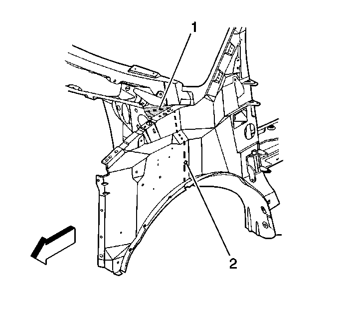
Important: The sectioned service part must be modified slightly to fit flush at the sectioning seam, and at the upper cowl panel and door frame opening weld flange.
Important: If the location of the original plug weld holes can not be determined, space the plug weld holes 40 mm (1½ in) apart.
