For 1990-2009 cars only
Special Tools
J 43218 Clamp Pliers - Narrow Jaw
Removal Procedure
- Raise the vehicle. Refer to Lifting and Jacking the Vehicle.
- Place an alignment mark between the rear inner tube (6) and the rear axle pinion yoke.
- Place an alignment mark between the outer tube and inner tube.
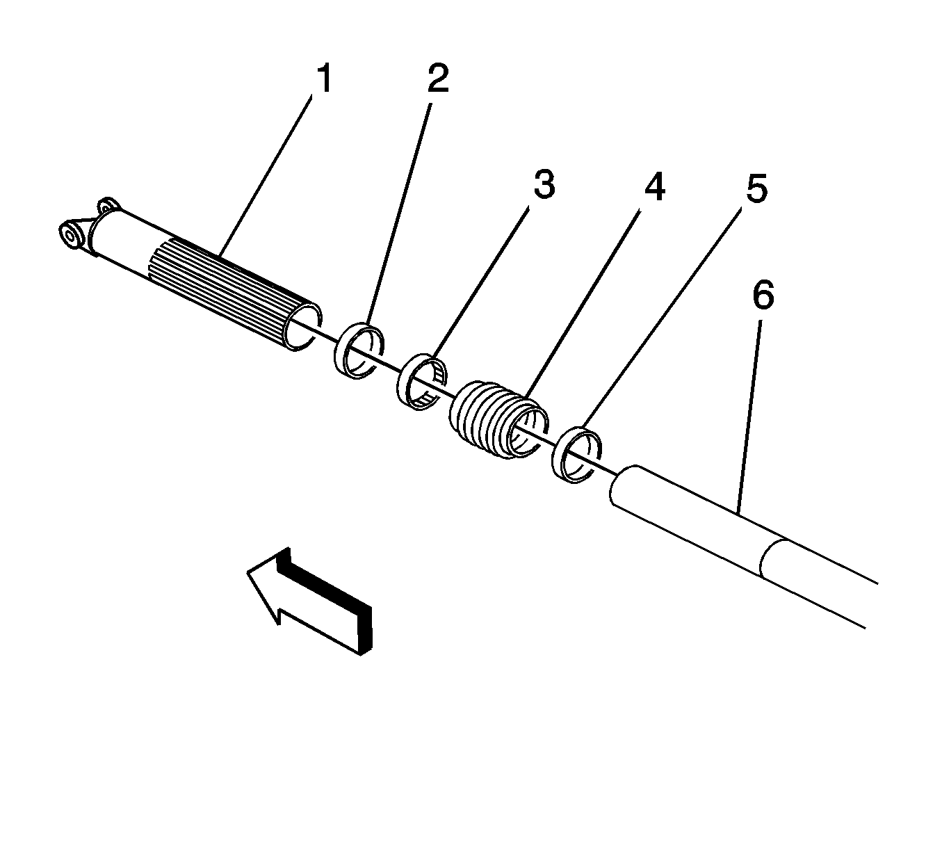
- Remove the clamps (2, 5) from the propeller shaft boot. Use a side cutter or other suitable tool. Discard the clamps.
- Support the outer shaft (6) with a suitable stand as necessary.
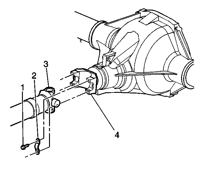
- Remove the bolts (1) and the yoke retainers (2) from the rear axle pinion yoke (4).
- Disconnect the propeller shaft (3) from the rear axle pinion yoke (4).
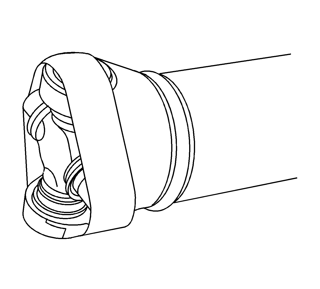
- Wrap the bearing caps with tape in order to prevent the loss of the needle bearings.
- Slide the rear inner tube (5) out of the outer tube (6) and remove the propeller shaft.

Note: The splines of the propshaft are not keyed.


Installation Procedure
- Clean the splines of the rear inner tube (6) and the outer tube (1).
- Inspect the outer and inner splines for damage. Replace the propeller shaft assembly if necessary.
- Apply grease, GM P/N 12345879 (Canadian P/N 109535511) or equivalent, to the splines of the rear inner tube (6).
- Install the bushing (3) on the outer tube (1). The flanged end of the bushing should be toward the rear of the vehicle.
- Install the 81.5 mm clamp (5) onto the rear inner tube (6). The size is stamped on the clamp.
- Install the 86.5 mm clamp (2) on the large diameter end of the boot (4). The size is stamped on the clamp.
- Slide the boot (4) onto the rear inner tube (6), small diameter end toward the rear of the vehicle.
- Install the 81.5 mm clamp (5) onto the boot (4).
- Wipe off the excess grease from the tubes.
- Install the propeller shaft (3) to the rear axle pinion yoke (4). Align the shaft and the yoke using the marks made during removal.
- Install the yoke retainers (2) and the bolts (1) and tighten to 25 N·m (18 lb ft).
- Using the J 43218 or equivalent, crimp the outer tube clamp.
- Adjust the boot (4) length so that it is 124-134 mm (4.88-5.28 in) from end to end.
- Using the J 43218 or equivalent, crimp the rear inner tube side clamp.
- Lower the vehicle.

Note: The rear inner tube and outer tube splines are not keyed. It is important to observe the alignment marks made during removal during the installation process.
Utilizing the alignment marks made during removal, reassemble the rear inner tube to the outer tube.

Caution: Refer to Fastener Caution in the Preface section.

