For 1990-2009 cars only
Cleaning Procedure
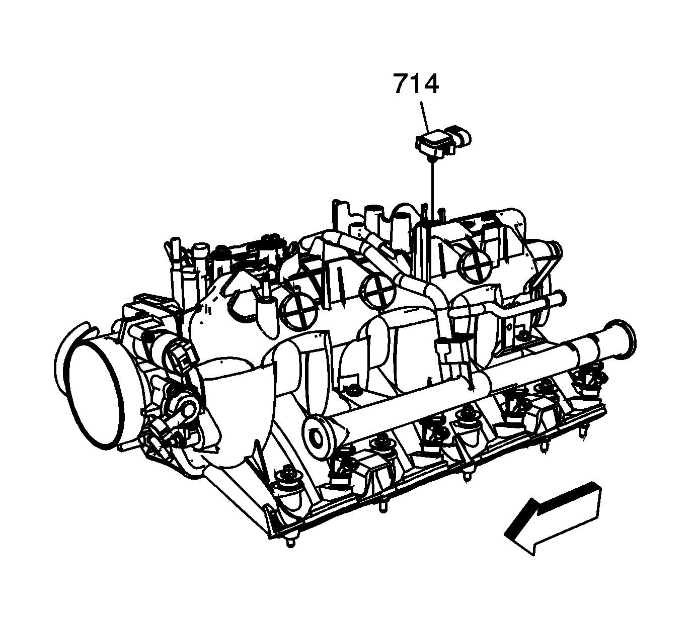
- Remove the manifold absolute pressure (MAP) sensor (714) from the rear of the intake. The MAP sensor is to be reinstalled upon completion of the cleaning and inspection procedures.
- Inspect the sealing grommet on the MAP sensor. The grommet should not be torn or damaged.
- Remove and discard the intake manifold-to-cylinder head gaskets (514).
- Remove the fuel rail with injectors. Refer to Fuel Rail and Injectors Removal .
- Remove the throttle body and gasket. Refer to Throttle Body Removal .
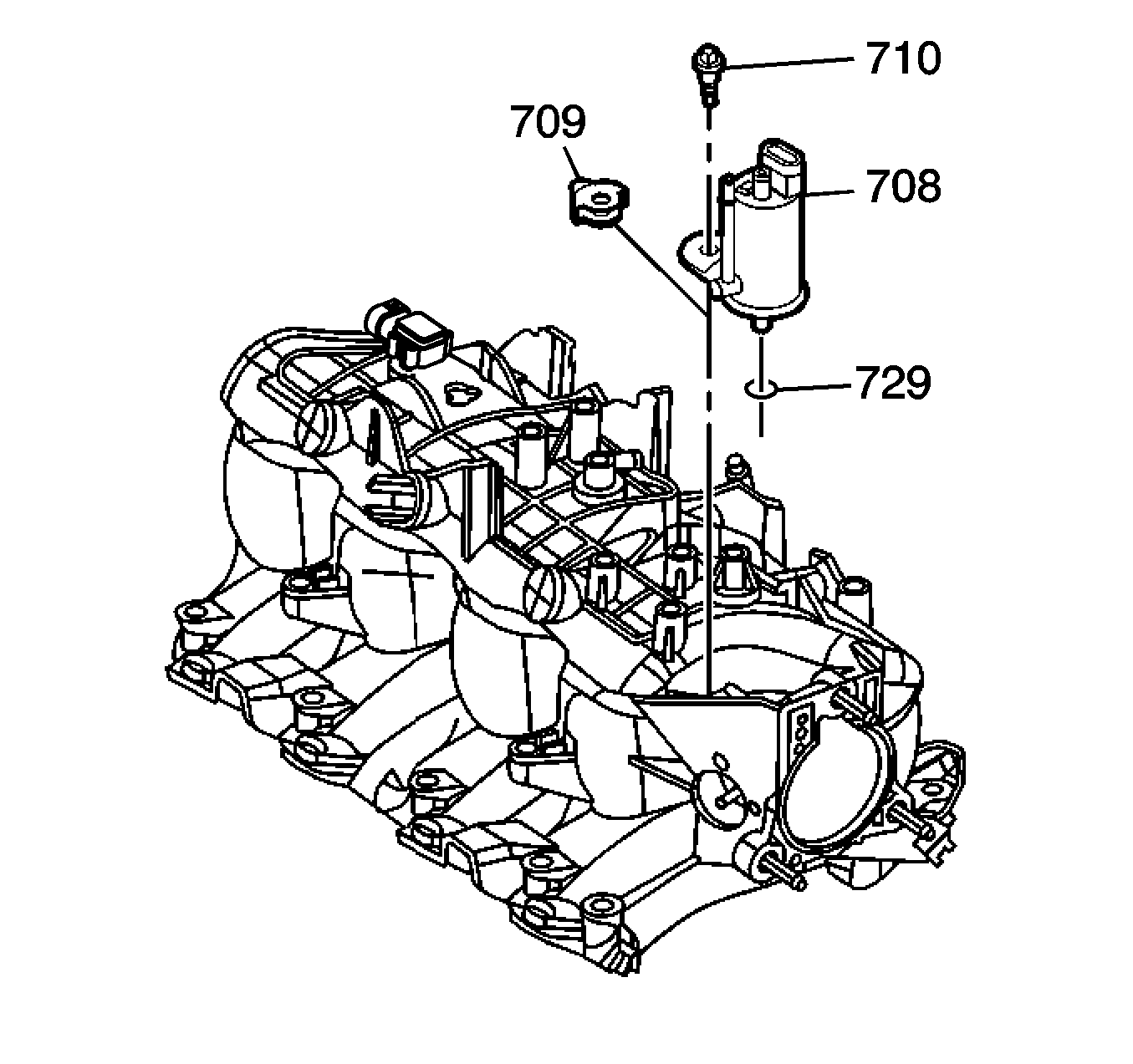
- Remove the evaporative emission (EVAP) canister purge solenoid valve (708), bolt (710), and isolator (709).
- Clean the intake manifold in solvent.
- Dry the intake manifold with compressed air.
Important: Do not use the intake manifold-to-cylinder head sealing gaskets again.
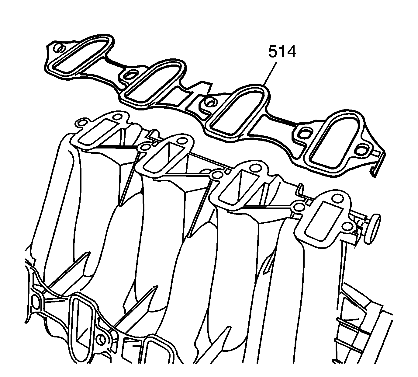
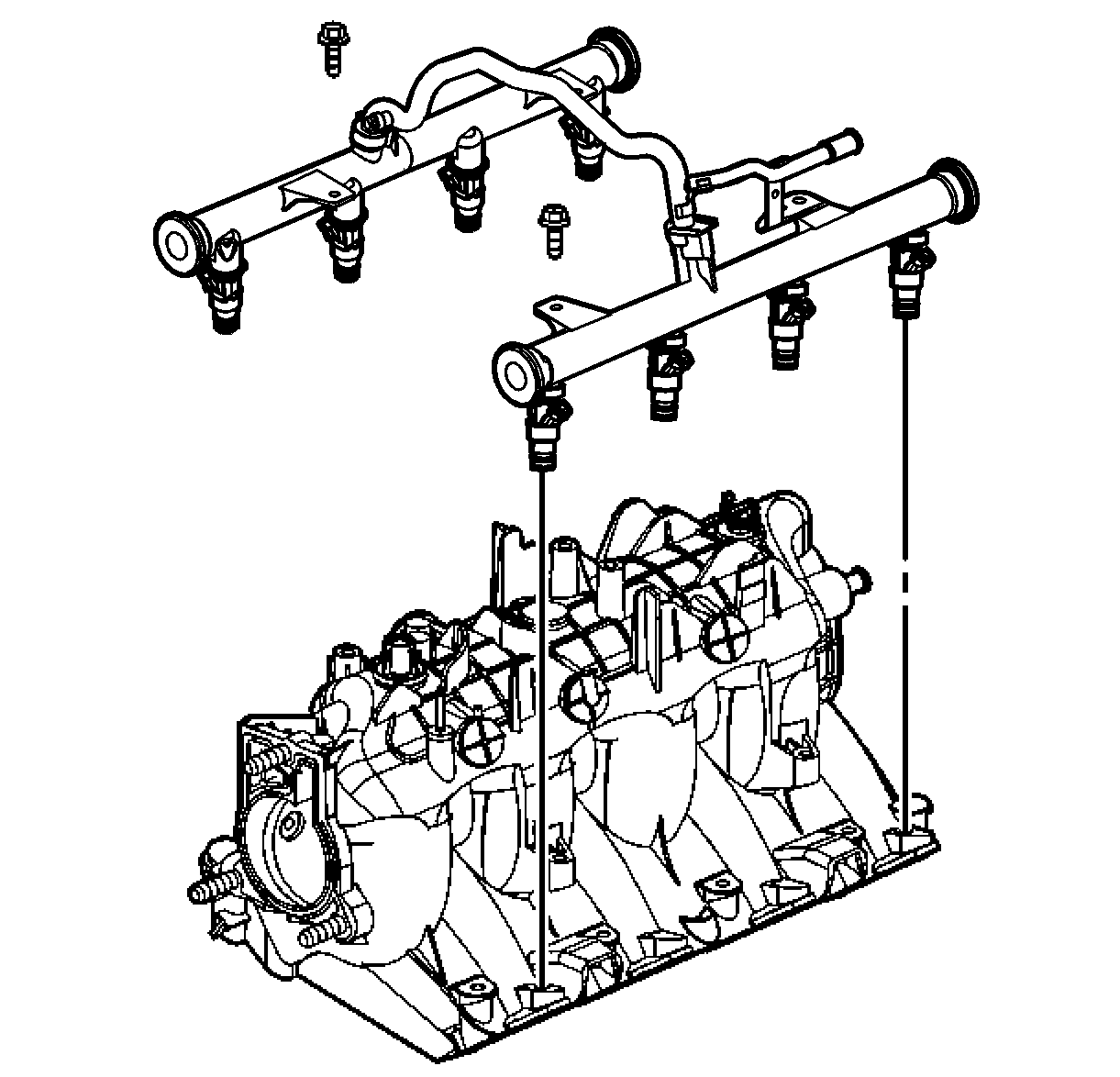
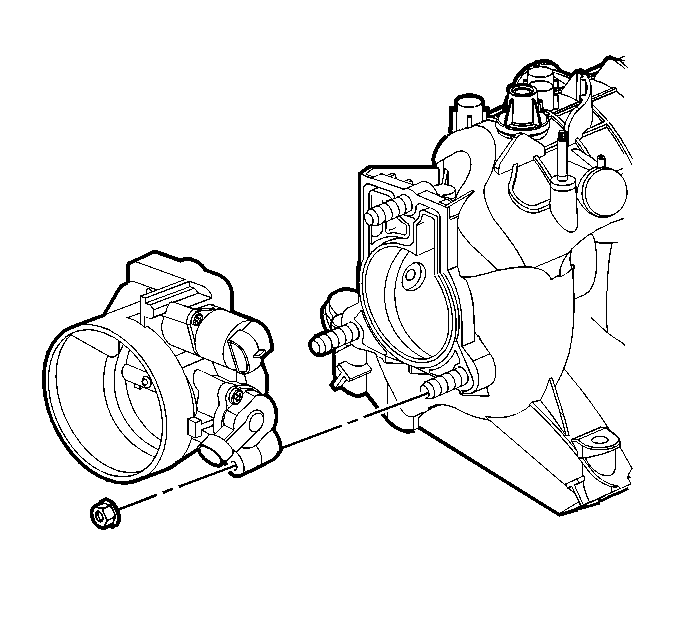
| • | Clean the intake manifold gasket surfaces. |
| • | Clean the intake manifold internal passages. |
Caution: Refer to Safety Glasses Caution in the Preface section.
Inspection Procedure
- Inspect the throttle body studs and threaded inserts for looseness or damaged threads.
- Inspect the wire harness stud and threaded insert for looseness or damaged threads.
- Inspect the fuel rail bolt inserts for looseness or damaged threads.
- Inspect the intake manifold vacuum passages for debris or restrictions.
- Inspect for damaged or broken vacuum fittings, damaged MAP sensor (714) mounting bore, or broken MAP sensor retaining tabs.
- Inspect the composite intake manifold assembly for cracks or other damage.
- Inspect all the gasket sealing surfaces for damage.
- Install the MAP sensor.
- Inspect the fuel injector bores for excessive scoring or damage.
- Inspect the intake manifold cylinder head deck for warpage.
- Install the EVAP canister purge solenoid valve (708), bolt (710), and isolator (709).


Inspect the areas between the intake runners.
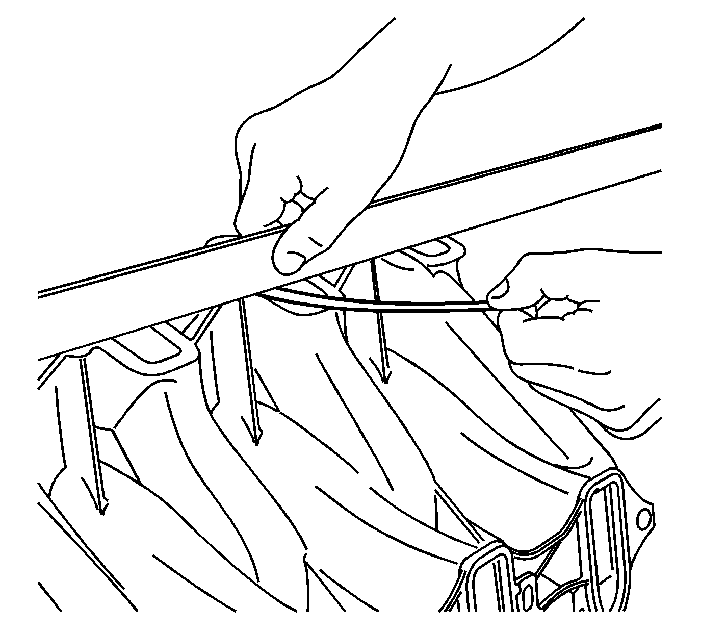
| 10.1. | Locate a straight edge across the intake manifold cylinder head deck surface. |
Position the straight edge across a minimum of two runner port openings.
| 10.2. | Insert a feeler gage between the intake manifold and the straight edge. |
A intake manifold with warpage in excess of 3 mm (0.118 in) over a 200 mm (7.87 in) area is warped and should be replaced.
Notice: Refer to Fastener Notice in the Preface section.

Tighten
Tighten the EVAP valve bolt to 10 N·m (89 lb in).
