Differential Carrier Assembly Bushing Replacement Inner Axle Shaft Housing
Tools Required
J 45850 Front Axle Bushing
Remover/Installer
Removal Procedure
- Remove the inner shaft housing. Refer to
Front Drive Axle Inner Shaft and Inner Shaft Housing Replacement
.
- If replacing the upper inner shaft housing bushing, install the inner
shaft housing into a vise.
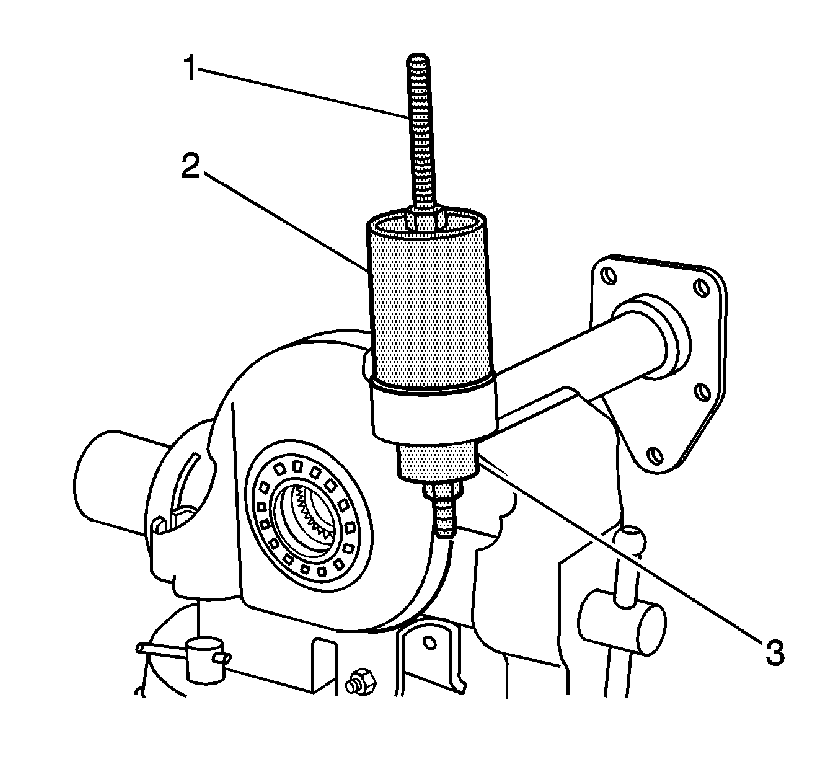
- Install the J 45850-2 (2), the J 45850-3 (3), the
forcing screw, the thrust bearing, the washers, and the nuts (1) over the upper
inner shaft housing bushing as shown.
- Remove the upper inner shaft housing bushing by holding the lower nut
and tightening the upper nut of the J 45850
.
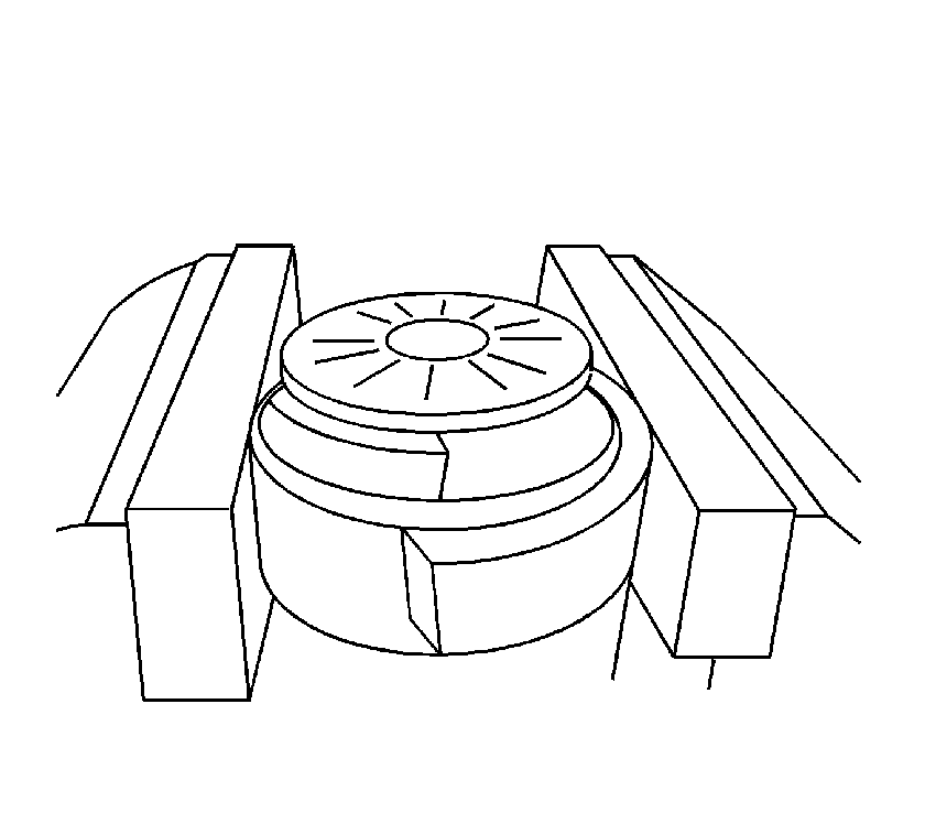
- If replacing the lower inner shaft housing bushing, install the inner shaft
housing into a vise so that the lower inner shaft bushing bore is flush with the jaws
of the vise.
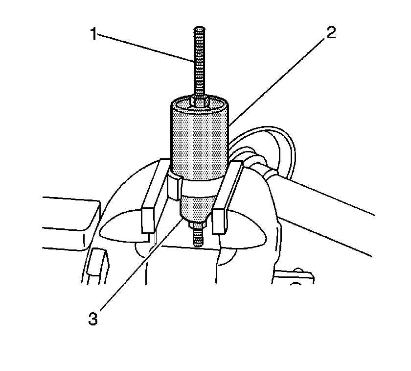
- Install the J 45850-2 (2), J 45850-3 (3), the forcing
screw, the thrust bearing, the washers, and the nuts (1) over the lower inner
shaft housing bushing as shown.
- Remove the lower inner shaft housing bushing by holding the lower nut
and tightening the upper nut of the J 45850
.
Installation Procedure
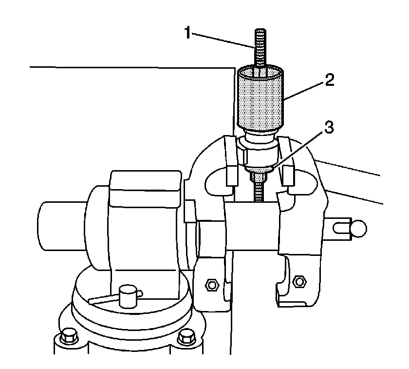
- If replacing the
lower inner shaft housing bushing, install the inner shaft housing bushing bore into
a vise.
- Place the lower inner shaft housing bushing over the bushing bore.
- Install the J 45850-2 (2), J 45850-1 (3),
the forcing screw, the thrust bearing, the washers, and the nuts (1) over the
inner shaft housing bushing as shown.
Install the J 45850-3 inside the J 45850-2 (2)
in order to gain access to the upper nut.
- Install the lower inner shaft bushing by holding the lower nut and slowly
tightening the upper nut in order to pull the bushing into the bushing bore.
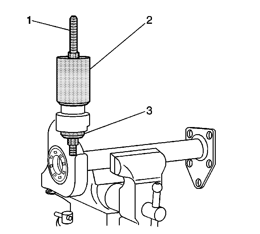
- If replacing the upper inner shaft housing bushing, install the inner shaft
housing bushing bore into a vise.
- Place the upper inner shaft housing bushing over the bushing bore.
- Install the J 45850-2 (2), J 45850-1 (3),
the forcing screw, the thrust bearing, the washers, and the nuts (1) over the
inner shaft housing bushing as shown.
Install the J 45850-3 inside the J 45850-2 (2)
in order to gain access to the upper nut.
- Install the upper inner shaft bushing by holding the lower nut and slowly
tightening the upper nut in order to pull the bushing into the bushing bore.
- Remove the inner shaft housing from the vise.
- Install the inner shaft housing. Refer to
Front Drive Axle Inner Shaft and Inner Shaft Housing Replacement
.
Differential Carrier Assembly Bushing Replacement Differential Carrier
Tools Required
J 45850 Front Axle Bushing
Remover/Installer
Removal Procedure
- Remove the differential carrier assembly. It is not necessary to drain
the differential carrier assembly. Seal the vent tube opening with a piece of tape
to prevent the axle lubricant from leaking from the differential carrier assembly.
Refer to
Differential Carrier Assembly Replacement
.
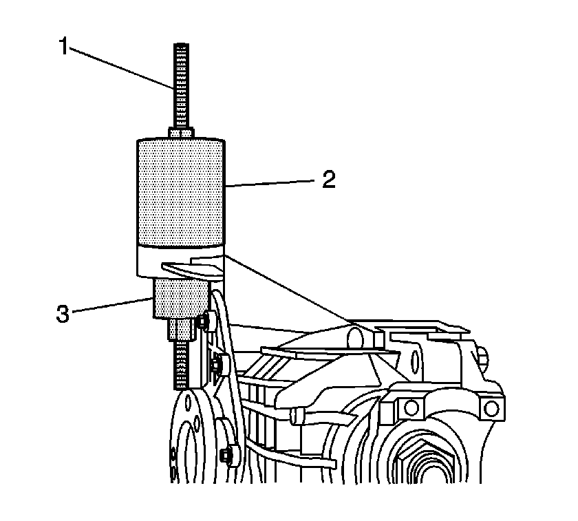
- If replacing the upper differential carrier assembly bushing, remove the bushing
by performing the following steps:
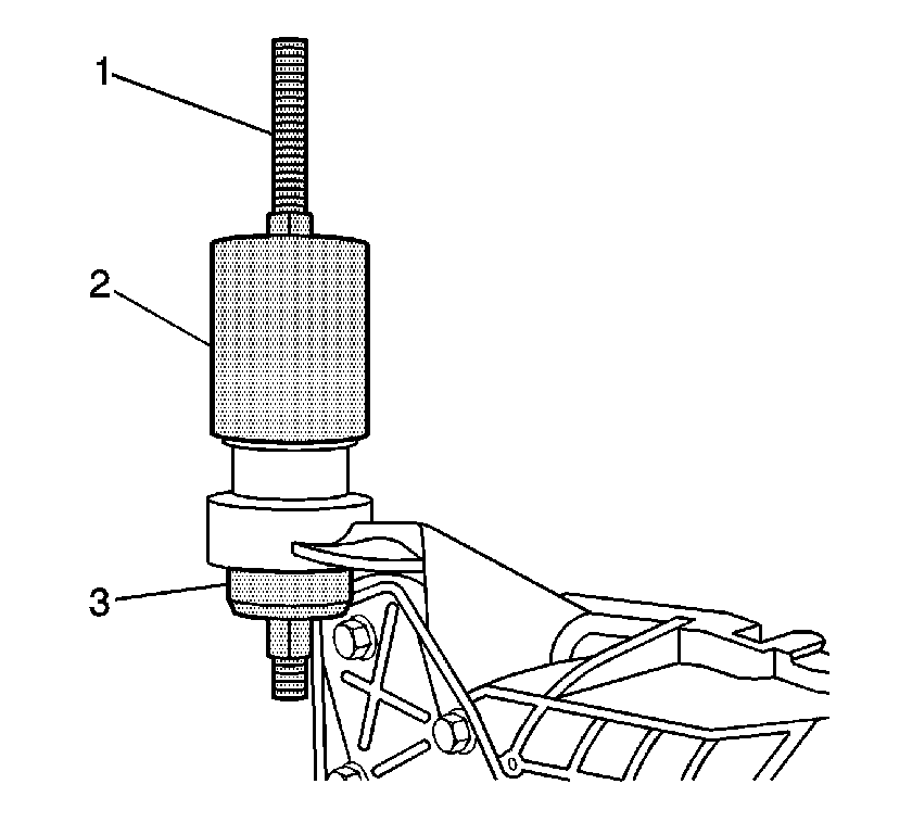
| 2.1. | Install the J 45850-2 (2), the J 45850-3 (3),
the forcing screw, the thrust bearing, the washers, and the nuts (1) over the
differential carrier assembly bushing as shown. |
| 2.2. | Remove the upper differential carrier assembly bushing by holding the
lower nut and tightening the upper nut of the J 45850
. |
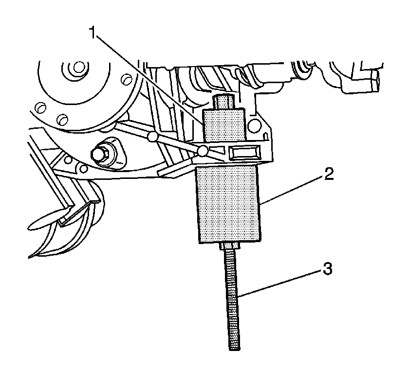
- If replacing the lower differential carrier assembly bushing, remove the bushing
by performing the following steps:
| 3.1. | Install the J 45850-2 (2), the J 45850-3 (1),
the forcing screw, the thrust bearing, and the nuts (3) over the differential
carrier assembly bushing as shown. |
| 3.2. | Remove the lower differential carrier assembly bushing by holding the
upper nut and tightening the lower nut of the J 45850
. |
Installation Procedure
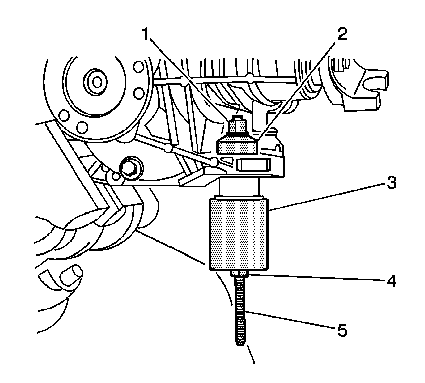
- If replacing the lower differential carrier assembly bushing, install the bushing
by performing the following steps:
| 1.1. | Install the differential carrier assembly bushing into the differential
carrier assembly bushing bore. |
| 1.2. | Install the J 45850-2 (3), the J 45850-3 (2),
the forcing screw, the thrust bearing, and the nuts (1, 4-5) over the
differential carrier assembly bushing as shown. |
| 1.3. | Install the lower differential carrier assembly bushing by holding the
upper nut and tightening the lower nut of the J 45850
. |
- If replacing the upper differential carrier assembly bushing, install the bushing
by performing the following steps:
| 2.1. | Install the differential carrier assembly bushing into the differential
carrier assembly bushing bore. |
| 2.2. | Install the J 45850-2 (2), the J 45850-3 (3),
the forcing screw, the thrust bearing, the washers, and the nuts (1) over the
differential carrier assembly bushing as shown. |
| 2.3. | Install the upper differential carrier assembly bushing by holding the
lower nut and tightening the upper nut of the J 45850
. |
- Install the differential carrier assembly. Once the differential carrier
assembly is installed, remove the piece of tape in order to connect the vent hose.
Refer to
Differential Carrier Assembly Replacement
.


