Notice: Do not add anything electrical to your vehicle unless you check with your dealer first. Some electrical equipment can damage your vehicle and the damage would not be covered by your warranty. Some add-on electrical equipment can keep other components from working as they should.
Your vehicle has wiring provisions for a 12-volt accessory power supply. This supplement provides instructions for adding electrical accessories to the 9L4 12-volt power supply feeds on your vehicle's electrical system. Keep this information in your vehicle with your owner manual for future reference.
Your vehicle may have an air bag system. If it does, see "Servicing Your Air-Bag Equipped Vehicle" in the Index of your owner manual before attempting to add anything electrical to your vehicle.
Because there are so many modifications that can be made for many different bodies and accessories, GM cannot take responsibility for any changes made. Have electrical work done by an experienced electrical technician.
Notice: Improper wiring and overloading of wiring, connectors,
and components can cause damage to your vehicle. To help prevent damage to your vehicle,
all wiring must be:
• properly protected by fuses, etc., • properly routed so it is not cut, pinched, or rubbed by other parts of
the vehicle, • routed away from areas that get very hot, • the same size as the wire being attached to for proper fuse protection.
12-Volt Accessory Power Supply Installation Instructions
- Disconnect the negative (-) battery cable at the battery.
- The power supply harness is located under the instrument panel near the passenger side of the vehicle. Release the wire bundles from the power supply harness by removing the tape holding them in place. The wire bundle consists of the pink (IGN), orange battery (BAT) and black negative (NEG) wire feeds.
- Remove the 40-amp MegaFuse from the wire bundle.
- Prepare the wires that will be used to connect the power accessory you are adding. Do not remove the unused wires[semi ] instead, tape them back in their original position under the instrument panel.
- Install the accessory you are adding with 12-gage (3.0 mm) wire required for the power connection.
- If you have a gasoline vehicle, perform Steps 6 through 10. If you have a diesel vehicle, go directly to step 9.
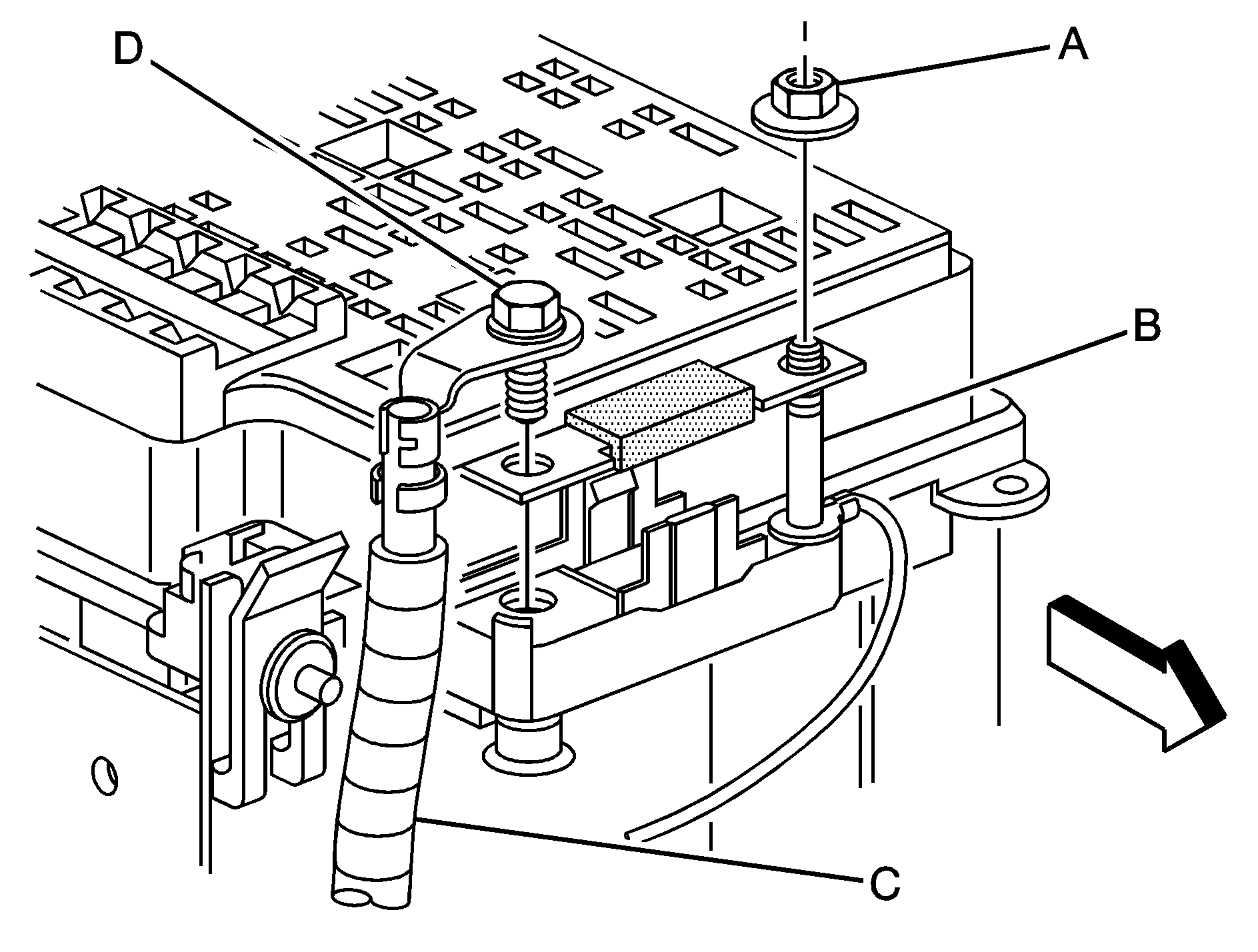
- Remove the bolt (D) to disconnect the positive (+) battery cable (C) at the underhood power distribution center. Then remove the nut (A) from stud (B).
- Install the 40-amp MegaFuse over the stud (B) in the underhood power distribution center.
- Install the positive (+) battery cable with the bolt (D) through the MegaFuse terminal. Replace the nut (A) on the stud (B). Torque the nut (A) and bolt (D) to 1.3 - 2.7 ft lb (6 -12 N·m).
- Connect the negative (-) battery cable to the battery. Torque the bolt to 12.5 ft lb (17 N·m).
- Reset the clock and radio buttons as needed. See your owner manual for more information.
| • | If you have a gasoline vehicle, set the fuse aside for installation after equipment wiring is complete. |
| • | If you have diesel vehicle, discard the fuse. |
Notice: If you attach cables to the battery with the ignition on, the vehicle control module (VCM) can be seriously damaged. Other vehicle components, like the radio, can also be damaged. Turn the ignition off and make sure all other vehicle accessories are turned off before attaching cables to the battery.
Underhood Power Distribution Center (Gasoline Application Only)

The IGN A and IGN B connections have voltage supplied and are hot when the ignition is turned to ACCESSORY or RUN (pink color wire).
The BAT A and BAT B connections have voltage supplied and are hot at all times (orange color wire).
Notice: Combining electrical
loads that exceed specified amperage may damage your vehicle. To prevent damage to
your vehicle:
• The combined electrical load of IGN A and BAT A must not
exceed 21 amps (250 watts). • The combined electrical load of IGN B and BAT B must not
exceed 21 amps (250 watts). • The combined electrical load of all circuits must not exceed 28 amps
(340 watts).
