C100 I/P Harness to Engine Harness (Gas w/o JL4)
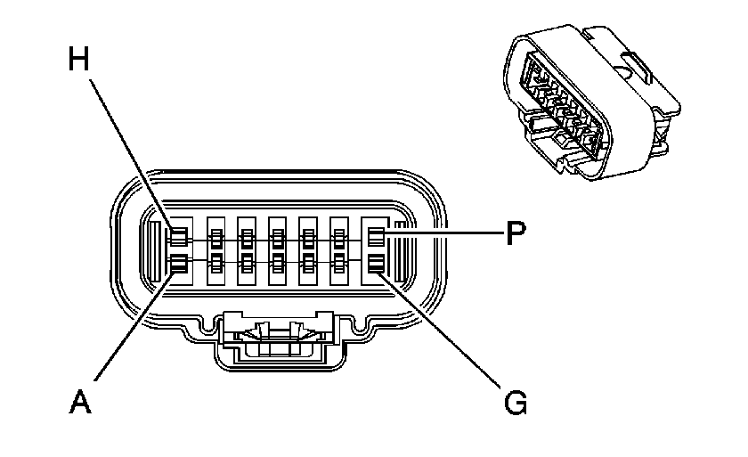
|
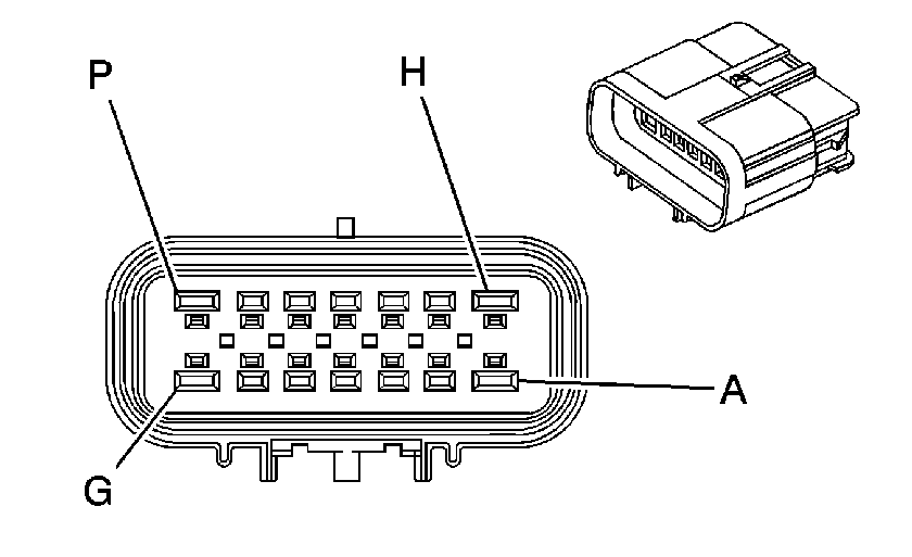
|
Connector Part Information
| Connector Part Information
|
Terminal Part Information
| Terminal Part Information
|
Pin | Wire Color | Circuit No. | Function | Pin | Wire Color | Circuit No. | Function |
|---|---|---|---|---|---|---|---|
A | OG | 52 | Blower Motor High Control | A | OG | 52 | Blower Motor High Control |
B | L-BU | 72 | Medium 2 Blower Motor Control | B | L-BU | 72 | Medium 2 Blower Motor Control |
C | YE | 60 | Blower Motor Low Control | C | YE | 60 | Blower Motor Low Control |
D | TN | 63 | Blower Motor Medium 1 Control | D | TN | 63 | Blower Motor Medium 1 Control |
E | OG | 1732 | Inadvertent Power Supply Voltage | E | OG | 1732 | Inadvertent Power Supply Voltage |
F | D-GN | 1049 | Class 2 Serial Data | F | D-GN | 1049 | Class 2 Serial Data |
G-H | -- | -- | Not Used | G-H | -- | -- | Not Used |
J | D-GN/WH | 817 | Vehicle Speed Signal (K34) | J | D-GN/WH | 817 | Vehicle Speed Signal |
K | BN/WH | 419 | MIL Control | K | BN/WH | 419 | MIL Control |
L | L-BU/BK | 396 | Cruise Control Engaged Signal (K34) | L | L-BU/BK | 396 | Cruise Control Engaged Signal |
M | D-GN | 83 | Cruise Control Inhibit Signal (K34) | M | D-GN | 83 | Cruise Control Inhibit Signal |
N | L-BU | 1122 | Class 2 Serial Data | N | L-BU | 1122 | Class 2 Serial Data |
P | L-GN | 66 | A/C Request Signal | P | L-GN | 66 | A/C Request Signal (C60) |
C100 Engine Harness to I/P Harness (JL4)
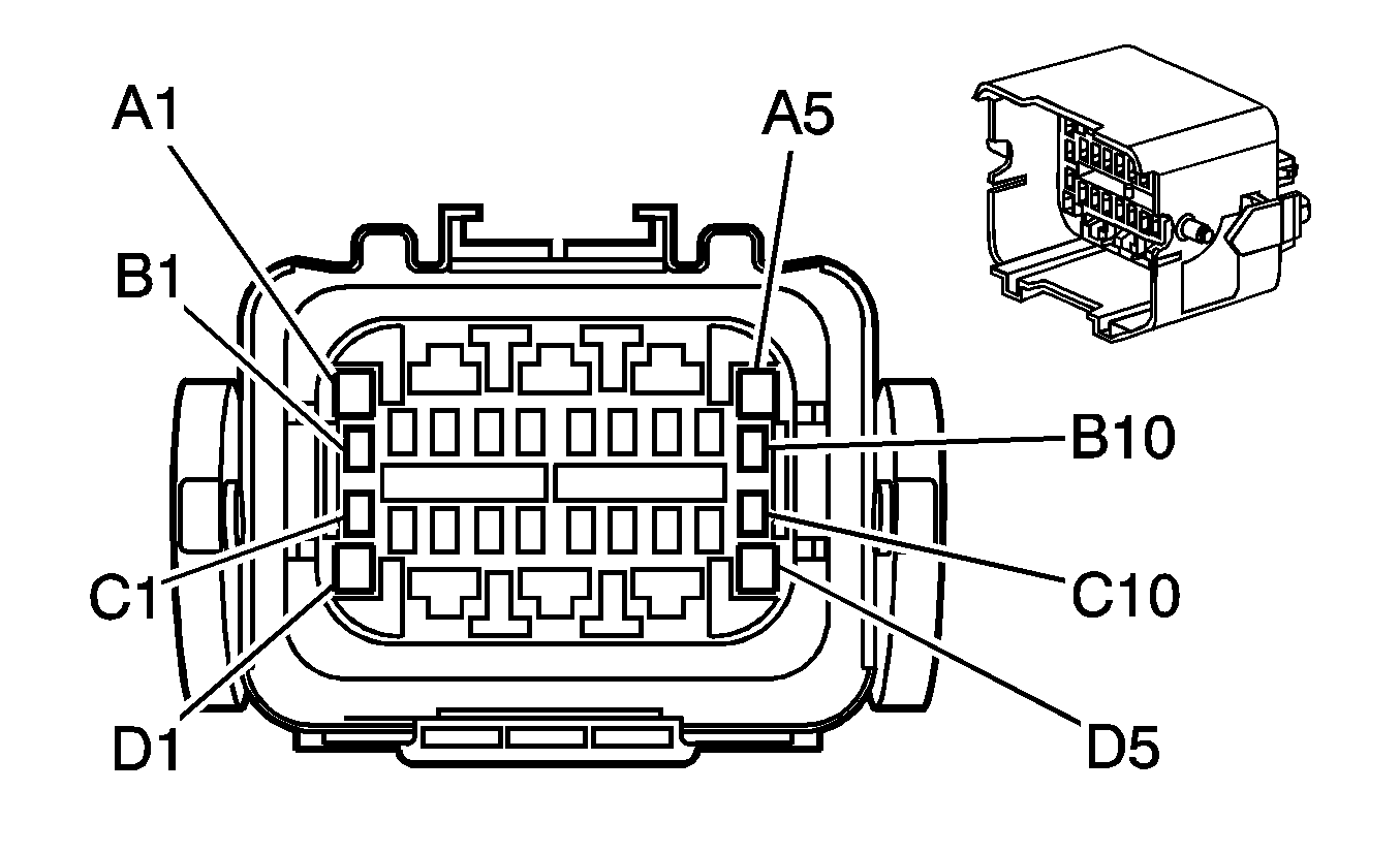
|
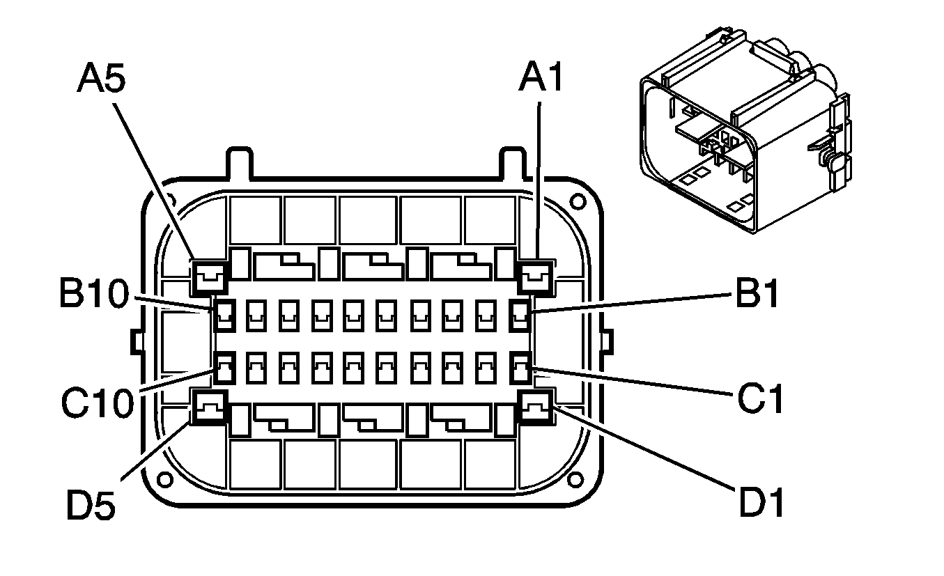
|
Connector Part Information
| Connector Part Information
|
Terminal Part Information
| Terminal Part Information
|
Pin | Wire Color | Circuit No. | Function | Pin | Wire Color | Circuit No. | Function |
|---|---|---|---|---|---|---|---|
A1 | L-BU | 1122 | Class 2 Serial Data | A1 | L-BU | 1122 | Class 2 Serial Data |
A2 | RD | 4042 | Battery Positive Voltage | A2 | RD | 4042 | Battery Positive Voltage |
A3 | OG | 52 | Blower Motor High Control | A3 | OG | 52 | Blower Motor High Control |
A4 | L-BU | 72 | Medium 2 Blower Motor Control | A4 | L-BU | 72 | Medium 2 Blower Motor Control |
A5 | L-BU | 2206 | Traction Control Preference Switch Signal | A5 | L-BU | 2206 | Traction Control Preference Switch Signal |
B1 | GY | 626 | 5-Volt Reference | B1 | GY | 626 | 5-Volt Reference |
B2 | L-BU | 1059 | Steering Wheel Position Sensor Signal 1 | B2 | L-BU | 1059 | Steering Wheel Position Sensor Signal 1 |
B3 | L-BU | 1764 | Steering Wheel Position Signal B | B3 | L-BU | 1764 | Steering Wheel Position Signal B |
B4 | D-BU | 84 | Cruise Control Set/Coast Switch Signal (K34) | B4 | D-BU | 84 | Cruise Control Set/Coast Switch Signal (K34) |
B5 | D-GN | 1049 | Class 2 Serial Data | B5 | D-GN | 1049 | Class 2 Serial Data |
B6 | -- | -- | Not Used | B6 | -- | -- | Not Used |
B7 | BN/WH | 419 | MIL Control | B7 | BN/WH | 419 | MIL Control |
B8 | D-GN | 2087 | Yaw Rate Sensor 5-Volt Reference | B8 | D-GN | 2087 | Yaw Rate Sensor 5-Volt Reference |
B9 | L-BU | 2088 | Yaw Rate Sensor Low Reference | B9 | L-BU | 2088 | Yaw Rate Sensor Low Reference |
B10 | L-GN/BK | 5352 | Sensor Self Test Signal Circuit | B10 | L-GN/BK | 5352 | Sensor Self Test Signal Circuit |
C1 | OG/BK | 556 | Steering Wheel Position Sensor Low Reference | C1 | OG/BK | 556 | Steering Wheel Position Sensor Low Reference |
C2 | L-GN | 1763 | Steering Wheel Position Signal A | C2 | L-GN | 1763 | Steering Wheel Position Signal A |
C3 | WH | 1765 | Steering Wheel Position Marker Pulse Signal | C3 | WH | 1765 | Steering Wheel Position Marker Pulse Signal |
C4 | -- | -- | Not Used | C4 | -- | -- | Not Used |
C5 | L-GN | 66 | A/C Request Signal | C5 | L-GN | 66 | A/C Request Signal |
C6 | GY/BK | 87 | Cruise Control Resume/Accel Switch Signal (K34) | C6 | GY/BK | 87 | Cruise Control Resume/Accel Switch Signal (K34) |
C7 | GY | 397 | Cruise Control On Switch Signal (K34) | C7 | GY | 397 | Cruise Control On Switch Signal (K34) |
C8 | D-BU | 716 | Yaw Rate Sensor Signal | C8 | D-BU | 716 | Yaw Rate Sensor Signal |
C9 | L-BU | 715 | Lateral Accelerometer Signal | C9 | L-BU | 715 | Lateral Accelerometer Signal |
C10 | YE | 5353 | Yaw Rate Frequency | C10 | YE | 5353 | Yaw Rate Frequency |
D1 | PK | 1339 | Ignition 1 Voltage | D1 | PK | 1339 | Ignition 1 Voltage |
D2 | YE | 60 | Blower Motor Low Control | D2 | YE | 60 | Blower Motor Low Control |
D3 | TN | 63 | Blower Motor Medium 1 Control | D3 | TN | 63 | Blower Motor Medium 1 Control |
D4 | L-BU | 1320 | CHMSL Supply Voltage/Stop Lamp Supply Voltage | D4 | L-BU | 1320 | CHMSL Supply Voltage/Stop Lamp Supply Voltage |
D5 | OG | 1732 | Inadvertent Power Supply Voltage | D5 | OG | 1732 | Inadvertent Power Supply Voltage |
C100 Engine Chassis Harness to I/P Harness (Diesel)

|

|
Connector Part Information
| Connector Part Information
|
Terminal Part Information
| Terminal Part Information
|
Pin | Wire Color | Circuit No. | Function | Pin | Wire Color | Circuit No. | Function |
|---|---|---|---|---|---|---|---|
A1 | L-BU | 1122 | Class 2 Serial Data | A1 | L-BU | 1122 | Class 2 Serial Data |
A2 | -- | -- | Not Used | A2 | -- | -- | Not Used |
A3 | OG | 52 | Blower Motor High Control | A3 | OG | 52 | Blower Motor High Control |
A4 | L-BU | 72 | Medium 2 Blower Motor Control | A4 | L-BU | 72 | Medium 2 Blower Motor Control |
A5 | BN | 1271 | Low Reference | A5 | BN | 1271 | Low Reference |
B1 | TN | 2501 | High Speed GMLAN Serial Data (-) | B1 | TN | 2501 | High Speed GMLAN Serial Data (-) |
B2 | YE | 343 | Accessory Voltage | B2 | YE | 343 | Accessory Voltage |
B3 | BN | 141 | Ignition 3 Voltage | B3 | BN | 141 | Ignition 3 Voltage |
B4 | D-BU | 84 | Cruise Control Set/Coast Switch Signal (K34) | B4 | D-BU | 84 | Cruise Control Set/Coast Switch Signal (K34) |
B5 | D-GN | 1049 | Class 2 Serial Data | B5 | D-GN | 1049 | Class 2 Serial Data |
B6 | D-GN | 534 | High Idle Switch Signal | B6 | D-GN | 534 | High Idle Switch Signal |
B7 | BN/WH | 419 | MIL Control | B7 | BN/WH | 419 | MIL Control |
B8 | PU | 1272 | Low Reference | B8 | PU | 1272 | Low Reference |
B9 | TN | 2501 | High Speed GMLAN Serial Data (-) | B9 | TN | 2501 | High Speed GMLAN Serial Data (-) |
B10 | TN | 1274 | 5-Volt Reference 2 | B10 | TN | 1274 | 5-Volt Reference 2 |
C1 | TN/BK | 2500 | High Speed GMLAN Serial Data (+) | C1 | TN/WH | 2500 | High Speed GMLAN Serial Data (+) |
C2 | D-BU | 1161 | APP Sensor 1 Signal | C2 | D-BU | 1161 | APP Sensor 1 Signal |
C3 | WH/BK | 1164 | 5-Volt Reference 3 | C3 | WH/BK | 1164 | 5-Volt Reference 3 |
C4 | D-BU | 507 | Wait to Start Indicator Control | C4 | D-BU | 507 | Wait to Start Indicator Control |
C5 | L-GN | 66 | A/C Request Signal (C60) | C5 | L-GN | 66 | A/C Request Signal (C60) |
C6 | GY/BK | 87 | Cruise Control Resume/Accel Switch Signal (K34) | C6 | GY/BK | 87 | Cruise Control Resume/Accel Switch Signal (K34) |
C7 | GY | 397 | Cruise Control On Switch Signal (K34) | C7 | GY | 397 | Cruise Control On Switch Signal (K34) |
C8 | OG | 2013 | High Idle Indicator Control | C8 | OG | 2013 | High Idle Indicator Control |
C9 | TN/BK | 2500 | High Speed GMLAN Serial Data (+) | C9 | TN/WH | 2500 | High Speed GMLAN Serial Data (+) |
C10 | L-BU | 1162 | APP Sensor 2 Signal | C10 | L-BU | 1162 | APP Sensor 2 Signal |
D1 | -- | -- | Not Used | D1 | -- | -- | Not Used |
D2 | YE | 60 | Blower Motor Low Control | D2 | YE | 60 | Blower Motor Low Control |
D3 | TN | 63 | Blower Motor Medium 1 Control | D3 | TN | 63 | Blower Motor Medium 1 Control |
D4 | L-BU | 1320 | CHMSL Supply Voltage/Stop Lamp Supply Voltage | D4 | L-BU | 1320 | CHMSL Supply Voltage/Stop Lamp Supply Voltage |
D5 | OG | 1732 | Inadvertent Power Supply Voltage | D5 | OG | 1732 | Inadvertent Power Supply Voltage |
C101 Engine Harness to Chassis Harness (Gas w/o JL4)
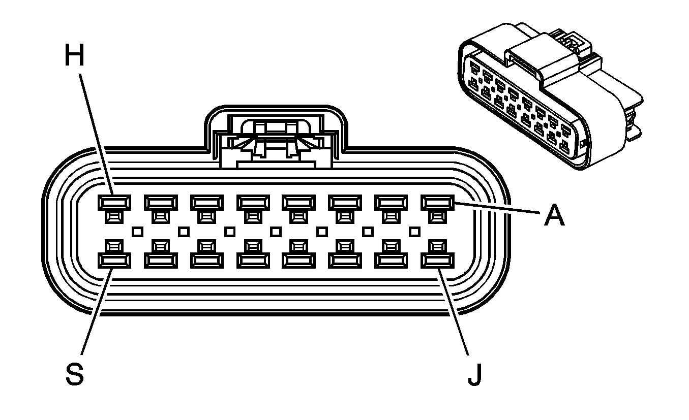
|
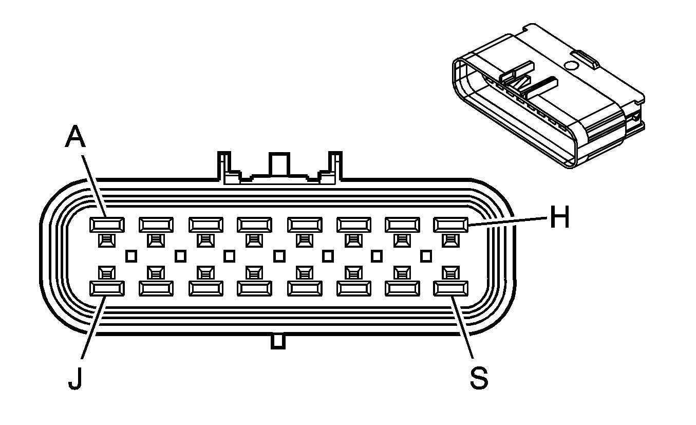
|
Connector Part Information
| Connector Part Information
|
Terminal Part Information
| Terminal Part Information
|
Pin | Wire Color | Circuit No. | Function | Pin | Wire Color | Circuit No. | Function |
|---|---|---|---|---|---|---|---|
A | YE/BK | 1827 | Vehicle Speed Signal | A | YE/BK | 1827 | Vehicle Speed Signal |
B | GY | 2709 | 5-Volt Reference 2 | B | GY | 2709 | 5-Volt Reference 2 |
C | TN | 2759 | Low Reference | C | BK | 2759 | Low Reference |
D | D-GN | 890 | Fuel Tank Pressure Sensor Signal | D | D-GN | 890 | Fuel Tank Pressure Sensor Signal |
E | PU | 333 | Brake Fluid Level Switch Signal (Heavy Duty) | E | PU | 333 | Brake Fluid Level Switch Signal (Heavy Duty) |
F | PU | 1589 | Fuel Level Sensor Signal | F | PU/WH | 1589 | Fuel Level Sensor Signal |
G | -- | -- | Not Used | G | -- | -- | Not Used |
H | WH | 1310 | EVAP Canister Vent Solenoid Control | H | WH | 1310 | EVAP Canister Vent Solenoid Control |
J | RD/WH | 140 | Battery Positive Voltage | J | OG | 140 | Battery Positive Voltage |
K | L-BU | 1122 | Class 2 Serial Data | K | L-BU | 1122 | Class 2 Serial Data |
L-S | -- | -- | Not Used | L-S | -- | -- | Not Used |
C101 Chassis Harness to Engine Harness (JL4)

|

|
Connector Part Information
| Connector Part Information
|
Terminal Part Information
| Terminal Part Information
|
Pin | Wire Color | Circuit No. | Function | Pin | Wire Color | Circuit No. | Function |
|---|---|---|---|---|---|---|---|
A1 | D-GN | 2087 | Yaw Rate Sensor 5-Volt Reference | A1 | D-GN | 2087 | Yaw Rate Sensor 5-Volt Reference |
A2 | L-BU | 2088 | Yaw Rate Sensor Low Reference | A2 | L-BU | 2088 | Yaw Rate Sensor Low Reference |
A3 | L-GN/BK | 5352 | Sensor Self Test Signal Circuit | A3 | L-GN/BK | 5352 | Sensor Self Test Signal Circuit |
A4 | YE/BK | 1827 | Vehicle Speed Signal | A4 | YE/BK | 1827 | Vehicle Speed Signal |
A5 | GY | 2709 | 5-Volt Reference 2 | A5 | GY | 2709 | 5-Volt Reference 2 |
B1 | BK | 2759 | Low Reference | B1 | TN | 2759 | Low Reference |
B2 | WH | 1765 | Steering Wheel Position Marker Pulse Signal | B2 | WH | 1765 | Steering Wheel Position Marker Pulse Signal |
B3-B4 | -- | -- | Not Used | B3-B4 | -- | -- | Not Used |
B5 | D-GN | 890 | Fuel Tank Pressure Sensor Signal | B5 | D-GN | 890 | Fuel Tank Pressure Sensor Signal |
B6 | PU | 333 | Brake Fluid Level Switch Signal (Heavy Duty) | B6 | PU | 333 | Brake Fluid Level Switch Signal (Heavy Duty) |
B7 | PU/WH | 1589 | Fuel Level Sensor Signal | B7 | PU | 1589 | Fuel Level Sensor Signal |
B8 | GY | 626 | 5-Volt Reference | B8 | GY | 626 | 5-Volt Reference |
B9 | L-BU | 1059 | Steering Wheel Position Sensor Signal 1 | B9 | L-BU | 1059 | Steering Wheel Position Sensor Signal 1 |
B10 | L-BU | 1764 | Steering Wheel Position Signal B | B10 | L-BU | 1764 | Steering Wheel Position Signal B |
C1 | D-BU | 716 | Yaw Rate Sensor Signal | C1 | D-BU | 716 | Yaw Rate Sensor Signal |
C2 | L-BU | 715 | Lateral Accelerometer Signal | C2 | L-BU | 715 | Lateral Accelerometer Signal |
C3 | YE | 5353 | Yaw Rate Frequency | C3 | YE | 5353 | Yaw Rate Frequency |
C4 | WH | 1310 | EVAP Canister Vent Solenoid Control | C4 | WH | 1310 | EVAP Canister Vent Solenoid Control |
C5 | OG | 140 | Battery Positive Voltage | C5 | RD/WH | 140 | Battery Positive Voltage |
C6 | L-BU | 1122 | Class 2 Serial Data | C6 | L-BU | 1122 | Class 2 Serial Data |
C7 | TN/BK | 464 | Delivered Torque Signal | C7 | TN/BK | 464 | Delivered Torque Signal |
C8 | OG/BK | 463 | Requested Torque Signal | C8 | OG/BK | 463 | Requested Torque Signal |
C9 | L-BU | 2206 | Traction Control Preference Switch Signal | C9 | L-BU | 2206 | Traction Control Preference Switch Signal |
C10 | OG/BK | 556 | Steering Wheel Position Sensor Low Reference | C10 | OG/BK | 556 | Steering Wheel Position Sensor Low Reference |
D1 | L-GN | 1763 | Steering Wheel Position Signal A | D1 | L-GN | 1763 | Steering Wheel Position Signal A |
D2 | BK | 2150 | Ground | D2 | -- | -- | Not Used |
D3 | RD | 4042 | Battery Positive Voltage | D3 | RD | 4042 | Battery Positive Voltage |
D4-D5 | -- | -- | Not Used | D4-D5 | -- | -- | Not Used |
C101 Chassis Harness to Engine Chassis Harness (Diesel)

|

|
Connector Part Information
| Connector Part Information
|
Terminal Part Information
| Terminal Part Information
|
Pin | Wire Color | Circuit No. | Function | Pin | Wire Color | Circuit No. | Function |
|---|---|---|---|---|---|---|---|
A1 | PK | 139 | Ignition 1 Voltage | A1 | PK | 139 | Ignition 1 Voltage |
A2 | D-GN | 1433 | PNP Start Switch Signal | A2 | D-GN | 1433 | PNP Start Switch Signal |
A3 | PK | 339 | Ignition 1 Voltage | A3 | PK | 339 | Ignition 1 Voltage |
A4 | YE/BK | 1827 | Vehicle Speed Signal | A4 | YE/BK | 1827 | Vehicle Speed Signal |
A5 | GY | 773 | Transmission Range Switch Signal C | A5 | GY | 773 | Transmission Range Switch Signal C |
B1 | TN | 2759 | Low Reference | B1 | TN | 2759 | Low Reference |
B2 | OG/BK | 1786 | Park/Neutral Signal | B2 | OG/BK | 1786 | Park/Neutral Signal |
B3 | D-GN | 1324 | Backup Lamp Supply Voltage | B3 | D-GN | 1324 | Backup Lamp Supply Voltage |
B4 | L-GN | 275 | Park Neutral Position Switch Park Signal | B4 | L-GN | 275 | Park Neutral Position Switch Park Signal |
B5 | D-BU | 6863 | Low Reference | B5 | D-BU | 6863 | Low Reference |
B6 | PU | 333 | Brake Fluid Level/Pressure Switch Signal | B6 | PU | 333 | Brake Fluid Level/Pressure Switch Signal |
B7 | PU | 1589 | Fuel Level Sensor Signal | B7 | PU | 1589 | Fuel Level Sensor Signal |
B8 | TN/WH | 771 | Transmission Range Switch Signal A | B8 | TN/WH | 771 | Transmission Range Switch Signal A |
B9 | YE | 772 | Transmission Range Switch Signal B | B9 | YE | 772 | Transmission Range Switch Signal B |
B10 | TN/BK | 2500 | High Speed GMLAN Serial Data (+) | B10 | TN/BK | 2500 | High Speed GMLAN Serial Data (+) |
C1 | OG/BK | 1228 | PC Solenoid Valve High Control | C1 | OG/BK | 1228 | PC Solenoid Valve High Control |
C2 | YE/BK | 508 | Water In Fuel Indicator Control | C2 | YE/BK | 508 | Water In Fuel Indicator Control |
C3 | L-GN | 1222 | 1-2 Shift Solenoid Valve Control | C3 | L-GN | 1222 | 1-2 Shift Solenoid Valve Control |
C4 | YE/BK | 1223 | 2-3 Shift Solenoid Valve Control | C4 | YE/BK | 1223 | 2-3 Shift Solenoid Valve Control |
C5 | BN | 418 | TCC PWM Solenoid Valve Control | C5 | BN | 418 | TCC PWM Solenoid Valve Control |
C6 | L-BU | 1122 | Class 2 Serial Data | C6 | L-BU | 1122 | Class 2 Serial Data |
C7 | PK | 1224 | Transmission Fluid Pressure Switch Signal A | C7 | PK | 1224 | Transmission Fluid Pressure Switch Signal A |
C8 | D-BU | 1225 | Transmission Fluid Pressure Switch Signal B | C8 | D-BU | 1225 | Transmission Fluid Pressure Switch Signal B |
C9 | OG | 1226 | Transmission Fluid Pressure Switch Signal C | C9 | OG | 1226 | Transmission Fluid Pressure Switch Signal C |
C10 | TN | 2501 | High Speed GMLAN Serial Data (-) | C10 | TN | 2501 | High Speed GMLAN Serial Data (-) |
D1 | L-BU/WH | 1229 | PC Solenoid Valve Low Control | D1 | L-BU/WH | 1229 | PC Solenoid Valve Low Control |
D2 | PK | 439 | Ignition 1 Voltage | D2 | PK | 439 | Ignition 1 Voltage |
D3-D4 | -- | -- | Not Used | D3-D4 | -- | -- | Not Used |
D5 | WH | 776 | Transmission Range Switch Signal P | D5 | WH | 776 | Transmission Range Switch Signal P |
C103 Engine Harness to Knock Sensor Harness (4.8L/5.3L/6.0L)
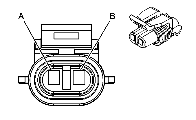
|
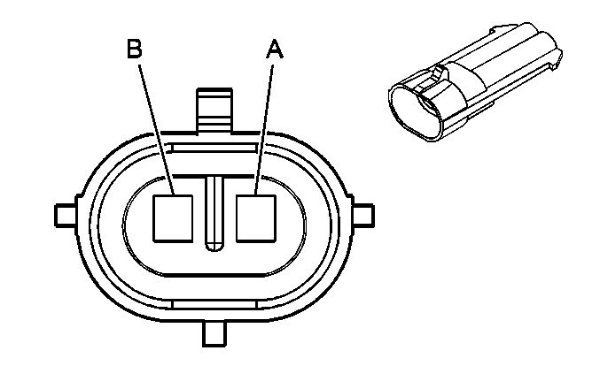
|
Connector Part Information
| Connector Part Information
|
Terminal Part Information
| Terminal Part Information
|
Pin | Wire Color | Circuit No. | Function | Pin | Wire Color | Circuit No. | Function |
|---|---|---|---|---|---|---|---|
A | D-BU | 496 | Knock Sensor 1 Signal | A | D-BU | 496 | Knock Sensor 1 Signal |
B | L-BU | 1876 | Knock Sensor 2 Signal | B | L-BU | 1876 | Knock Sensor 2 Signal |
C104 I/P Harness to Front End Sensor Jumper Harness (Heavy Duty)
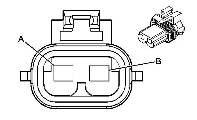
|
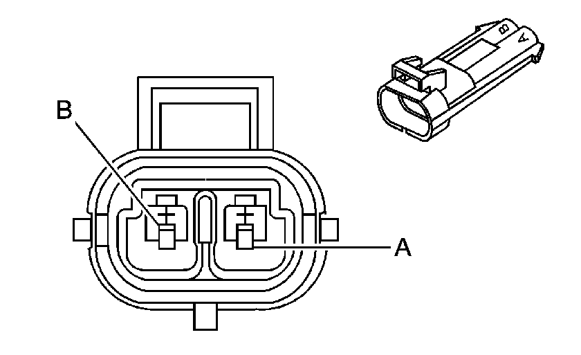
|
Connector Part Information
| Connector Part Information
|
Terminal Part Information
| Terminal Part Information
|
Pin | Wire Color | Circuit No. | Function | Pin | Wire Color | Circuit No. | Function |
|---|---|---|---|---|---|---|---|
A | YE | 354 | Front End Sensor - Signal | A | YE | 354 | Front End Sensor - Signal |
B | TN/OG | 5045 | Front End Sensor - Low Reference | B | TN/OG | 5045 | Front End Sensor - Low Reference |
C104 I/P Harness to Front End Sensor Jumper Harness (Light Duty)
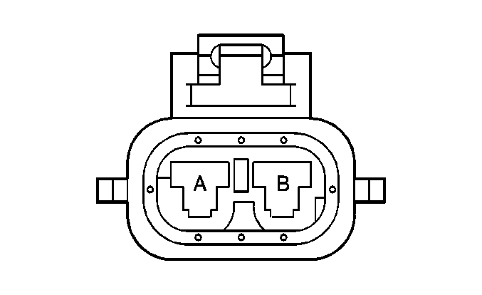
|
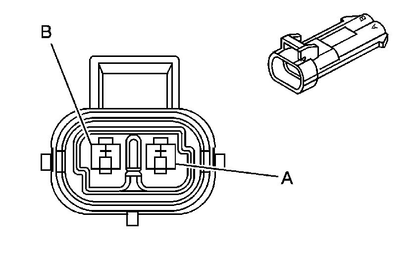
|
Connector Part Information
| Connector Part Information
|
Terminal Part Information
| Terminal Part Information
|
Pin | Wire Color | Circuit No. | Function | Pin | Wire Color | Circuit No. | Function |
|---|---|---|---|---|---|---|---|
A | YE | 354 | Front End Sensor - Signal | A | YE | 354 | Front End Sensor - Signal |
B | TN/OG | 5045 | Front End Sensor - Low Reference | B | TN/OG | 5045 | Front End Sensor - Low Reference |
C105 Engine Chassis Harness to Chassis Harness (Diesel)
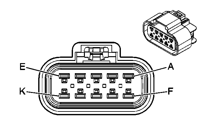
|
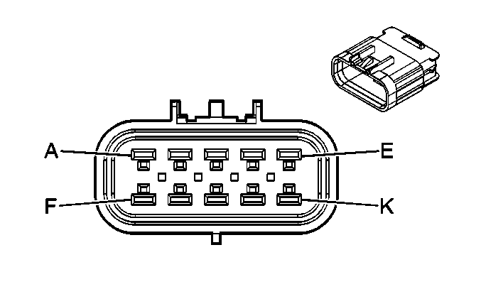
|
Connector Part Information
| Connector Part Information
|
Terminal Part Information
| Terminal Part Information
|
Pin | Wire Color | Circuit No. | Function | Pin | Wire Color | Circuit No. | Function |
|---|---|---|---|---|---|---|---|
A | TN/BK | 2500 | High Speed GMLAN Serial Data (+) | A | TN/BK | 2500 | High Speed GMLAN Serial Data (+) |
B | TN | 2501 | High Speed GMLAN Serial Data (-) | B | TN | 2501 | High Speed GMLAN Serial Data (-) |
C | YE | 400 | VSS High Signal | C | YE | 400 | VSS High Signal |
D | PU | 401 | VSS Low Signal | D | PU | 401 | VSS Low Signal |
E | -- | -- | Not Used | E | -- | -- | Not Used |
F | OG/BK | 1230 | A/T ISS High Signal | F | OG/BK | 1230 | A/T ISS High Signal |
G | D-BU/WH | 1231 | A/T ISS Low Signal | G | D-BU/WH | 1231 | A/T ISS Low Signal |
H | YE/BK | 1227 | TFT Sensor Signal | H | YE/BK | 1227 | TFT Sensor Signal |
J | D-BU/WH | 2762 | Low Reference | J | TN | 2762 | Low Reference |
K | -- | -- | Not Used | K | -- | -- | Not Used |
C107 Engine Harness to Engine Chassis Harness (Diesel)
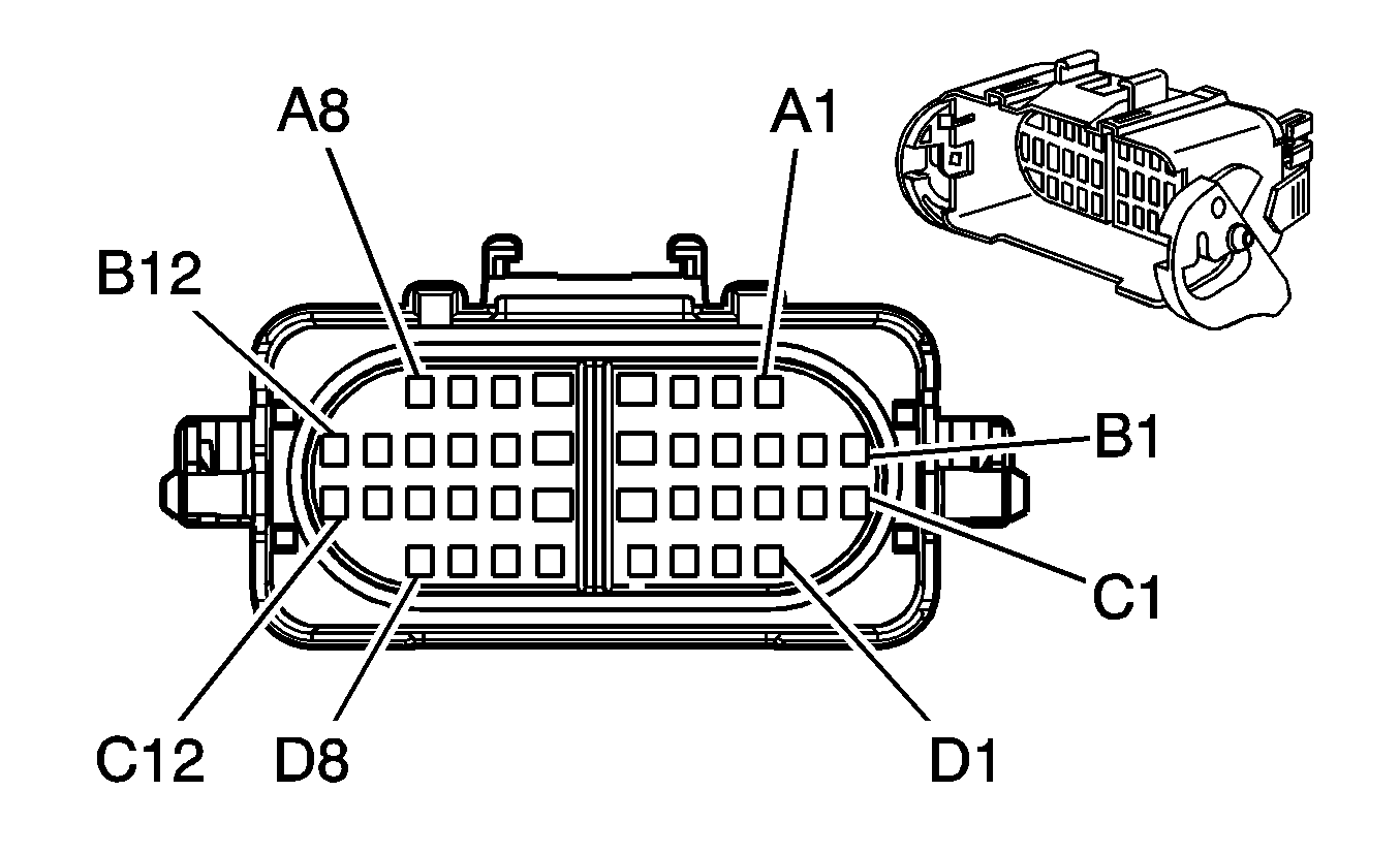
|
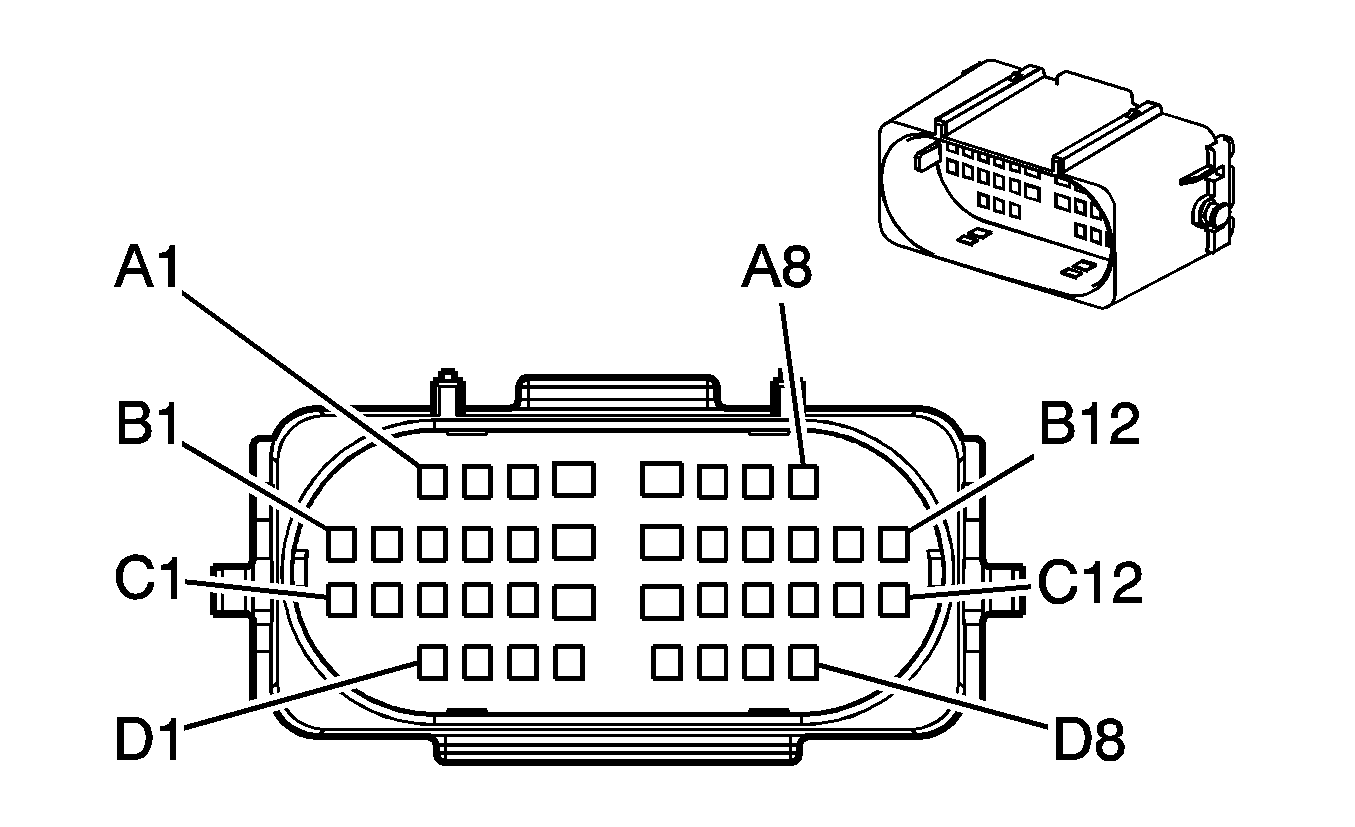
|
Connector Part Information
| Connector Part Information
|
Terminal Part Information
| Terminal Part Information
|
Pin | Wire Color | Circuit No. | Function | Pin | Wire Color | Circuit No. | Function |
|---|---|---|---|---|---|---|---|
A1 | TN | 5928 | 5-Volt Reference 3 | A1 | TN | 5928 | 5-Volt Reference 3 |
A2 | OG/BK | 5929 | Low Reference | A2 | OG/BK | 5929 | Low Reference |
A3 | YE | 5947 | Turbocharger Vane Position Sensor Signal | A3 | YE | 5947 | Turbocharger Vane Position Sensor Signal |
A4 | TN | 1744 | Fuel Injector 1 Control Group 1 | A4 | TN | 1744 | Fuel Injector 1 Control Group 1 |
A5 | OG | 5421 | Injector Positive Voltage Control | A5 | OG | 5421 | Injector Positive Voltage Control |
A6 | GY | 2704 | 5-Volt Reference 3 | A6 | GY | 2704 | 5-Volt Reference 3 |
A7 | OG/BK | 469 | Low Reference | A7 | OG/BK | 469 | Low Reference |
A8 | L-GN | 432 | MAP Sensor Signal | A8 | L-GN | 432 | MAP Sensor Signal |
B1 | YE | 1578 | Fuel Temperature Sensor Signal | B1 | YE | 1578 | Fuel Temperature Sensor Signal |
B2 | BN | 6062 | Low Reference | B2 | BN | 6062 | Low Reference |
B3 | TN | 2501 | High Speed GMLAN Serial Data (-) | B3 | TN | 2501 | High Speed GMLAN Serial Data (-) |
B4 | TN/BK | 2500 | High Speed GMLAN Serial Data (+) | B4 | TN/BK | 2500 | High Speed GMLAN Serial Data (+) |
B5 | -- | -- | Not Used | B5 | -- | -- | Not Used |
B6 | L-BU/BK | 844 | Fuel Injector 4 Control Group 1 | B6 | L-BU/BK | 844 | Fuel Injector 4 Control Group 1 |
B7 | YE | 5422 | Injector Positive Voltage Control | B7 | YE | 5422 | Injector Positive Voltage Control |
B8-B12 | -- | -- | Not Used | B8-B12 | -- | -- | Not Used |
C1 | WH | 1020 | Ignition 0 Voltage | C1 | PK | 1020 | Ignition 0 Voltage |
C2 | GY | 2705 | 5-Volt Reference 2 | C2 | GY | 2705 | 5-Volt Reference 2 |
C3 | BK | 2755 | Low Reference | C3 | BK | 2755 | Low Reference |
C4 | TN/WH | 331 | Oil Pressure Sensor Signal | C4 | TN/WH | 331 | Oil Pressure Sensor Signal |
C5 | BN | 1174 | Oil Level Switch Signal | C5 | BN | 1174 | Oil Level Switch Signal |
C6 | YE/BK | 846 | Fuel Injector 6 Control Group 2 | C6 | YE/BK | 846 | Fuel Injector 6 Control Group 2 |
C7 | OG/BK | 877 | Fuel Injector 7 Control Group 2 | C7 | OG/BK | 877 | Fuel Injector 7 Control Group 2 |
C8 | D-BU | 5930 | Turbocharger Vane Position Control Solenoid Valve Control | C8 | D-BU | 5930 | Turbocharger Vane Position Control Solenoid Valve Control |
C9 | WH | 5931 | Low Reference | C9 | WH | 5931 | Low Reference |
C10 | PK | 439 | Ignition 1 Voltage | C10 | PK | 439 | Ignition 1 Voltage |
C11 | TN | 2501 | High Speed GMLAN Serial Data (-) | C11 | TN | 2501 | High Speed GMLAN Serial Data (-) |
C12 | TN/BK | 2500 | High Speed GMLAN Serial Data (+) | C12 | TN/BK | 2500 | High Speed GMLAN Serial Data (+) |
D1 | YE | 2834 | Fuel Pressure Regulator Solenoid Control | D1 | YE | 2834 | Fuel Pressure Regulator Solenoid Control |
D2 | PU/WH | 2530 | Fuel Pressure Regulator Solenoid Supply Voltage | D2 | PU/WH | 2530 | Fuel Pressure Regulator Solenoid Supply Voltage |
D3 | L-BU | 6118 | IAT Sensor 2 Signal | D3 | L-BU | 6118 | IAT Sensor 2 Signal |
D4-D5 | -- | -- | Not Available | D4-D5 | -- | -- | Not Available |
D6 | YE/BK | 6120 | Low Reference | D6 | YE/BK | 6120 | Low Reference |
D7 | YE | 410 | ECT Sensor Signal | D7 | YE | 410 | ECT Sensor Signal |
D8 | TN | 2761 | Low Reference | D8 | TN | 2761 | Low Reference |
C108 Engine Harness to Engine Chassis Harness (Diesel)
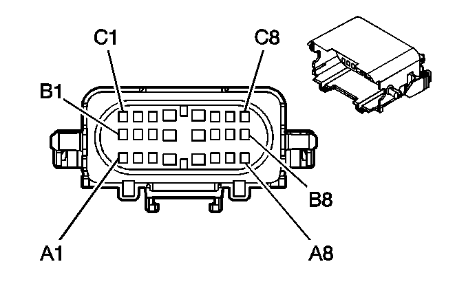
|
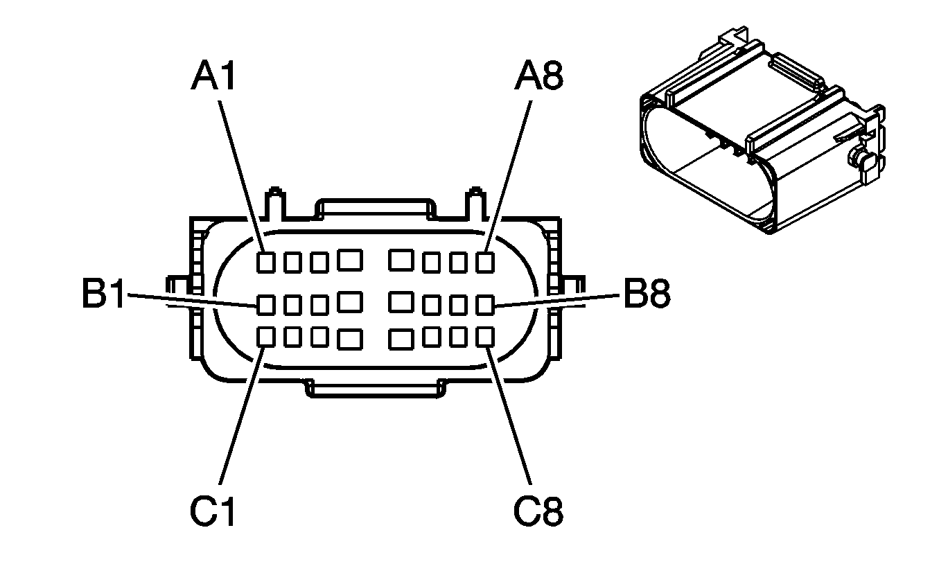
|
Connector Part Information
| Connector Part Information
|
Terminal Part Information
| Terminal Part Information
|
Pin | Wire Color | Circuit No. | Function | Pin | Wire Color | Circuit No. | Function |
|---|---|---|---|---|---|---|---|
A1 | TN | 2917 | 5-Volt Reference 2 | A1 | TN | 2917 | 5-Volt Reference 2 |
A2 | OG/BK | 2919 | Low Reference | A2 | OG/BK | 2919 | Low Reference |
A3 | YE | 2918 | FRP Sensor Signal | A3 | YE | 2918 | FRP Sensor Signal |
A4 | L-GN/BK | 1745 | Fuel Injector 2 Control Group 3 | A4 | L-GN/BK | 1745 | Fuel Injector 2 Control Group 3 |
A5 | PU | 5423 | Injector Positive Voltage Control | A5 | PU | 5423 | Injector Positive Voltage Control |
A6 | OG/BK | 5764 | EGR Motor High Control | A6 | OG/BK | 5764 | EGR Motor High Control |
A7 | L-GN/BK | 5746 | EGR Motor Low Control | A7 | L-GN/BK | 5746 | EGR Motor Low Control |
A8 | -- | -- | Not Used | A8 | -- | -- | Not Used |
B1 | PU/WH | 6270 | 5-Volt Reference 1 | B1 | PU/WH | 6270 | 5-Volt Reference 1 |
B2 | GY/BK | 6272 | Low Reference | B2 | GY/BK | 6272 | Low Reference |
B3 | WH/BK | 6271 | CKP Sensor Signal | B3 | WH/BK | 6271 | CKP Sensor Signal |
B4 | TN/WH | 845 | Fuel Injector 5 Control Group 3 | B4 | TN/WH | 845 | Fuel Injector 5 Control Group 3 |
B5 | PK | 5425 | Injector Positive Voltage Control | B5 | PK | 5425 | Injector Positive Voltage Control |
B6 | -- | -- | Not Used | B6 | -- | -- | Not Used |
B7 | GY | 2702 | 5-Volt Reference 3 | B7 | GY | 2702 | 5-Volt Reference 3 |
B8 | TN | 2753 | Low Reference | B8 | TN | 2753 | Low Reference |
C1 | D-BU | 6259 | 5-Volt Reference 1 | C1 | D-BU | 6259 | 5-Volt Reference 1 |
C2 | BN | 6266 | Low Reference | C2 | BN | 6266 | Low Reference |
C3 | D-BU/WH | 6265 | CMP Sensor Signal | C3 | D-BU/WH | 6265 | CMP Sensor Signal |
C4 | PK/BK | 1746 | Fuel Injector 3 Control Group 4 | C4 | PK/BK | 1746 | Fuel Injector 3 Control Group 4 |
C5 | D-BU/WH | 878 | Fuel Injector 8 Control Group 4 | C5 | D-BU/WH | 878 | Fuel Injector 8 Control Group 4 |
C6 | -- | -- | Not Used | C6 | -- | -- | Not Used |
C7 | BN/WH | 5763 | EGR Valve Position Signal | C7 | BN/WH | 5763 | EGR Valve Position Signal |
C8 | -- | -- | Not Used | C8 | -- | -- | Not Used |
C109 Engine (Gas)/Engine Chassis (Diesel) Harness to Underhood Lamp Harness

|

|
Connector Part Information
| Connector Part Information
|
Terminal Part Information
| Terminal Part Information
|
Pin | Wire Color | Circuit No. | Function | Pin | Wire Color | Circuit No. | Function |
|---|---|---|---|---|---|---|---|
A | OG | 1732 | Inadvertent Power Supply Voltage | A | OG | 1732 | Inadvertent Power Supply Voltage |
B | BK | 1250 | Ground | B | BK | 1250 | Ground |
C110 Engine Jumper Harness to Engine Harness (Diesel)
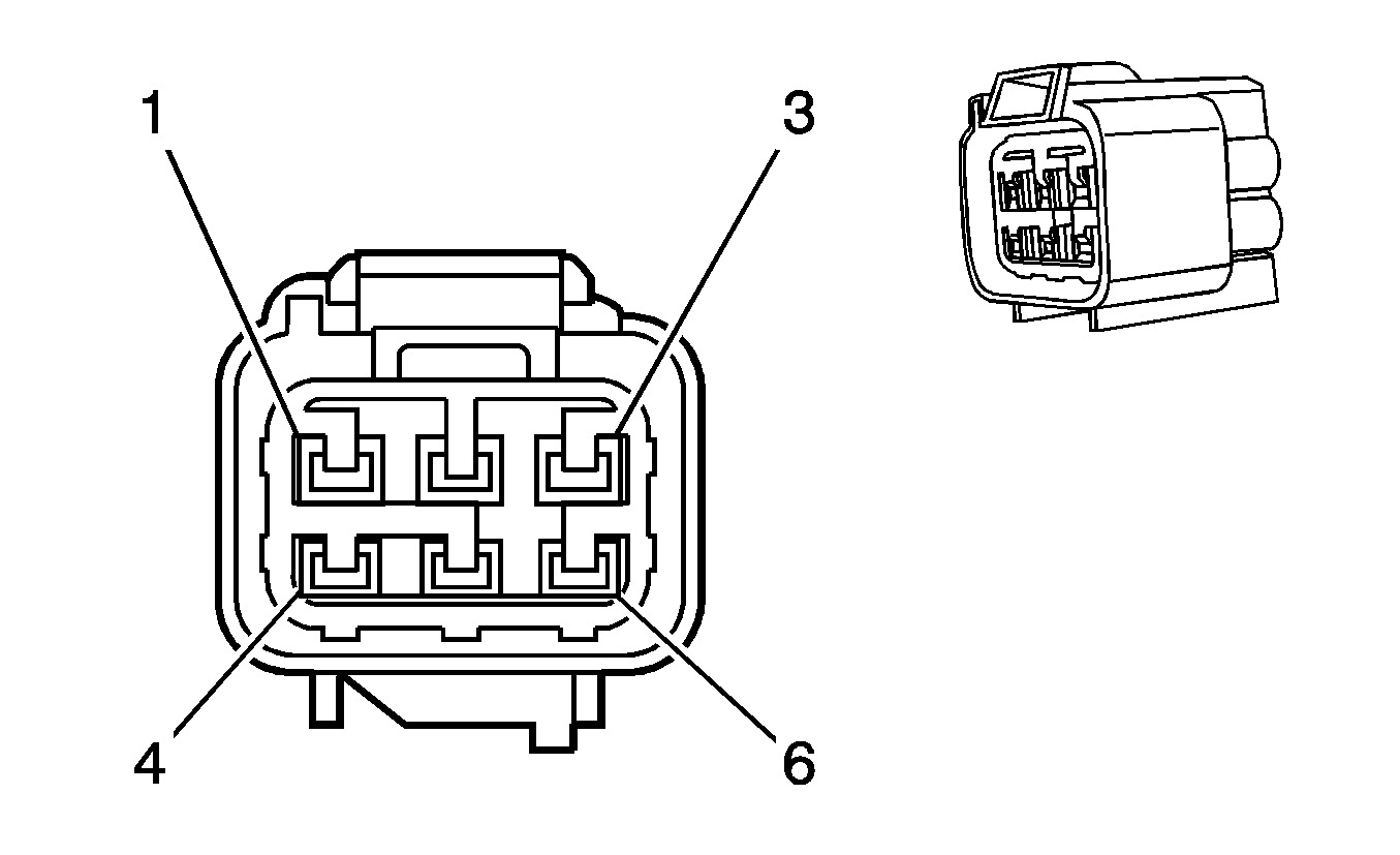
|
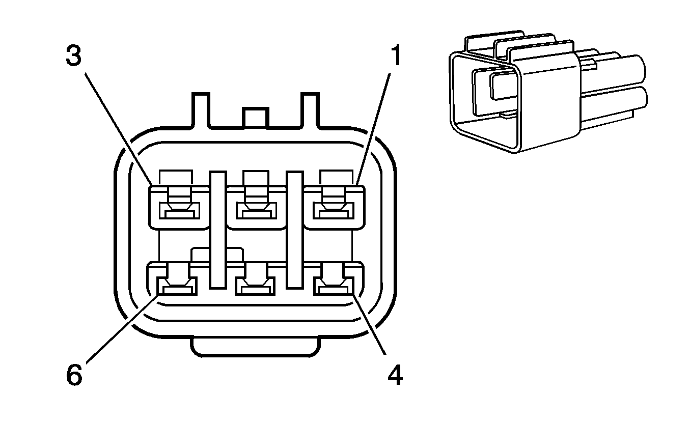
|
Connector Part Information
| Connector Part Information
|
Terminal Part Information
| Terminal Part Information
|
Pin | Wire Color | Circuit No. | Function | Pin | Wire Color | Circuit No. | Function |
|---|---|---|---|---|---|---|---|
1 | PK/YE | HB03 | Ground | 1 | RD | HB03 | Ground |
2 | TN/WH | 331 | Oil Pressure Sensor Signal | 2 | TN/WH | 331 | Oil Pressure Sensor Signal |
3 | BN | 1174 | Oil Level Switch Signal | 3 | BN | 1174 | Oil Level Switch Signal |
4 | GY | 2705 | 5-Volt Reference 2 | 4 | GY | 2705 | 5-Volt Reference 2 |
5 | BK | 2755 | Low Reference | 5 | BK | 2755 | Low Reference |
6 | -- | -- | Not Used | 6 | -- | -- | Not Used |
C111 Fuel Pressure Regulator (FPR)/Engine Coolant Temperature (ECT) Sensor Jumper Harness to Engine Harness (Diesel)

|

|
Connector Part Information
| Connector Part Information
|
Terminal Part Information
| Terminal Part Information
|
Pin | Wire Color | Circuit No. | Function | Pin | Wire Color | Circuit No. | Function |
|---|---|---|---|---|---|---|---|
1 | BK | IZ07 | Drain Wire | 1 | BK | IZ07 | Drain Wire |
2 | YE | 2834 | Fuel Pressure Regulator Solenoid Control | 2 | YE | 2834 | Fuel Pressure Regulator Solenoid Control |
3 | PU/WH | 2530 | Fuel Pressure Regulator Solenoid Supply Voltage | 3 | PU/WH | 2530 | Fuel Pressure Regulator Solenoid Supply Voltage |
4 | -- | -- | Not Used | 4 | -- | -- | Not Used |
5 | BK | 2761 | Low Reference | 5 | BK | 2761 | Low Reference |
6 | YE | 410 | ECT Sensor Signal | 6 | YE | 410 | ECT Sensor Signal |
C112 Fuel Rail Pressure (FRP) Sensor Jumper Harness to Engine Harness (Diesel)
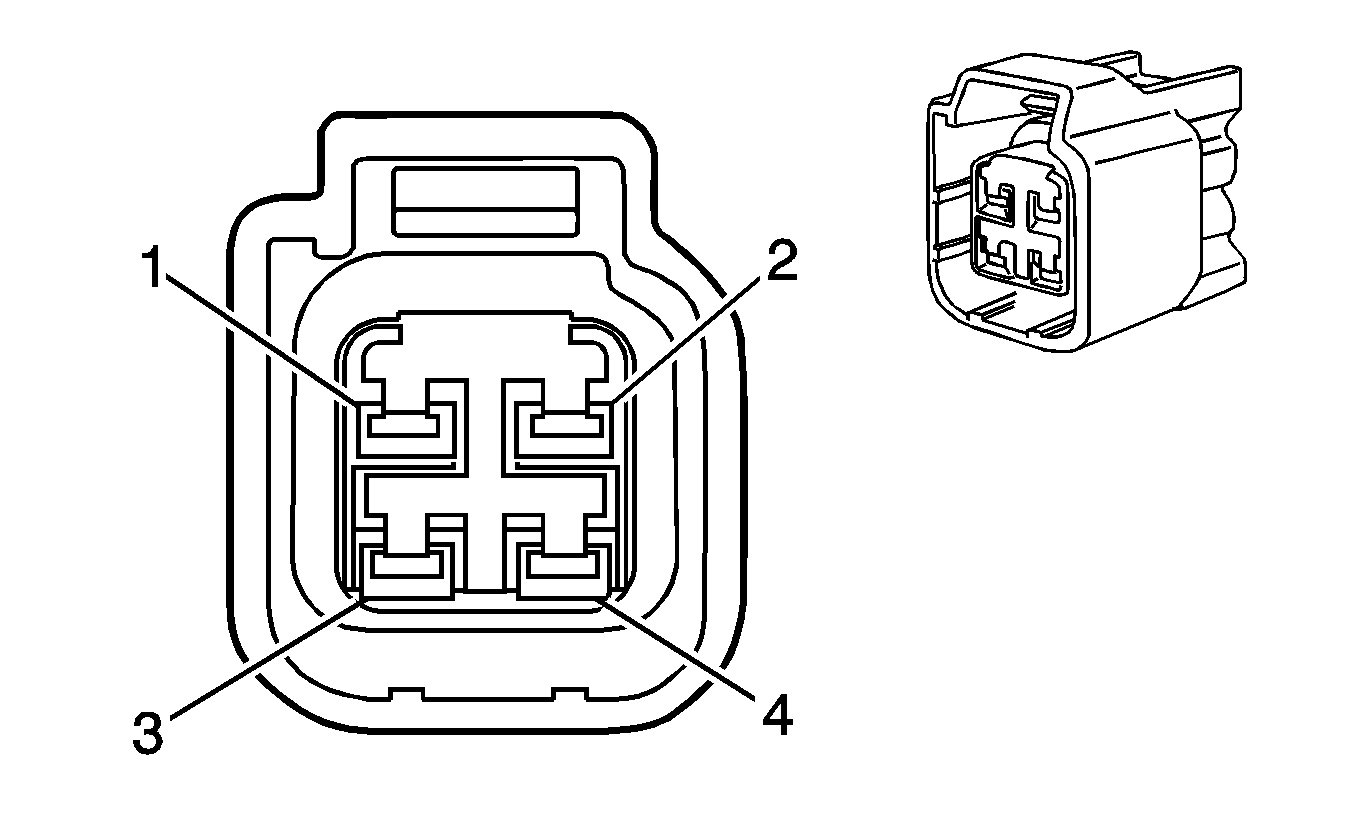
|
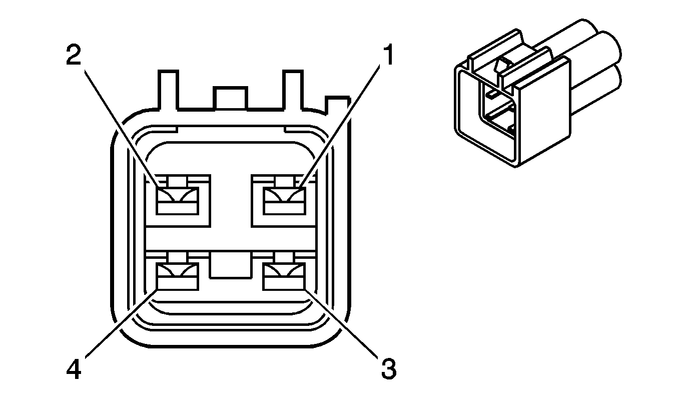
|
Connector Part Information
| Connector Part Information
|
Terminal Part Information
| Terminal Part Information
|
Pin | Wire Color | Circuit No. | Function | Pin | Wire Color | Circuit No. | Function |
|---|---|---|---|---|---|---|---|
1 | WH | 2919 | Low Reference | 1 | OG/BK | 2919 | Low Reference |
2 | OG/BK | 2918 | FRP Sensor Signal | 2 | YE | 2918 | FRP Sensor Signal |
3 | -- | -- | Not Used | 3 | -- | -- | Not Used |
4 | D-BU | 2917 | 5-Volt Reference 2 | 4 | TN | 2917 | 5-Volt Reference 2 |
C126 Engine Harness to Left Ignition Coil Harness (4.8L/5.3L/6.0L)
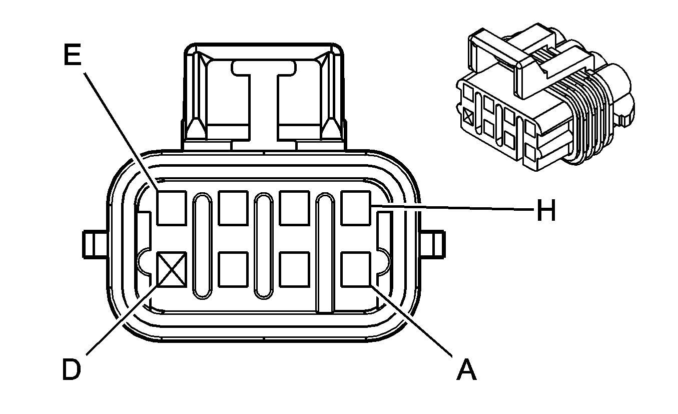
|
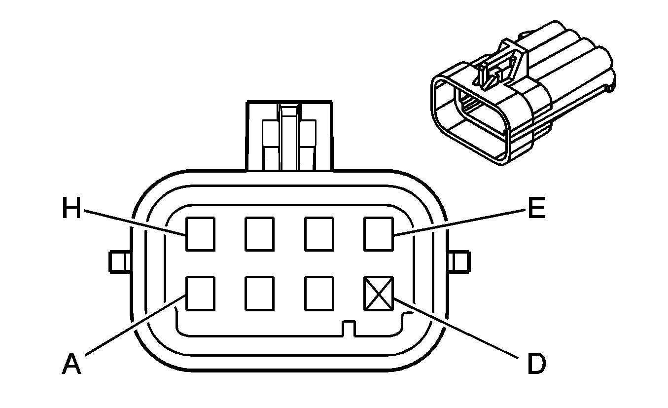
|
Connector Part Information
| Connector Part Information
|
Terminal Part Information
| Terminal Part Information
|
Pin | Wire Color | Circuit No. | Function | Pin | Wire Color | Circuit No. | Function |
|---|---|---|---|---|---|---|---|
A | BK | 1250 | Ground | A | BK | 151 | Ground |
B | OG | 2127 | IC 7 Control | B | RD | 2127 | IC 7 Control |
C | D-GN | 2125 | IC 5 Control | C | D-GN | 2125 | IC 5 Control |
D | -- | -- | Not Available | D | -- | -- | Not Available |
E | BN | 2129 | Low Reference | E | BN | 2129 | Low Reference |
F | L-BU | 2123 | IC 3 Control | F | L-BU | 2123 | IC 3 Control |
G | PU | 2121 | IC 1 Control | G | PU | 2121 | IC 1 Control |
H | PK | 139 | Ignition 1 Voltage | H | PK | 39 | Ignition 1 Voltage |
C127 Engine Harness to Right Ignition Coil Harness (4.8L/5.3L/6.0L)

|

|
Connector Part Information
| Connector Part Information
|
Terminal Part Information
| Terminal Part Information
|
Pin | Wire Color | Circuit No. | Function | Pin | Wire Color | Circuit No. | Function |
|---|---|---|---|---|---|---|---|
A | BK | 1250 | Ground | A | BK | 151 | Ground |
B | OG/WH | 2122 | IC 2 Control | B | RD | 2122 | IC 2 Control |
C | D-GN/WH | 2124 | IC 4 Control | C | D-GN | 2124 | IC 4 Control |
D | -- | -- | Not Available | D | -- | -- | Not Available |
E | BN/WH | 2130 | Low Reference | E | BN | 2129 | Low Reference |
F | L-BU/WH | 2126 | IC 6 Control | F | L-BU | 2126 | IC 6 Control |
G | PU/WH | 2128 | IC 8 Control | G | PU | 2128 | IC 8 Control |
H | PK | 239 | Ignition 1 Voltage | H | PK | 39 | Ignition 1 Voltage |
C128 Engine Harness to Oxygen Sensor Harness (4.8L/6.0L)
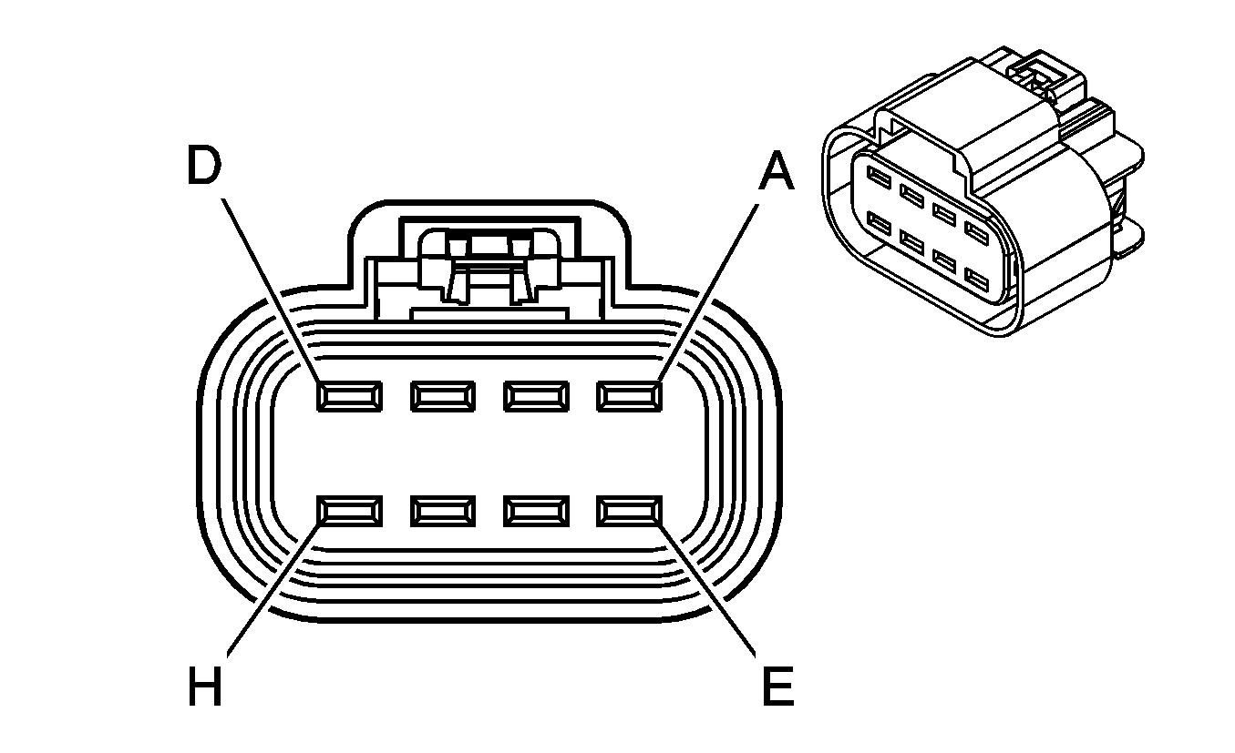
|
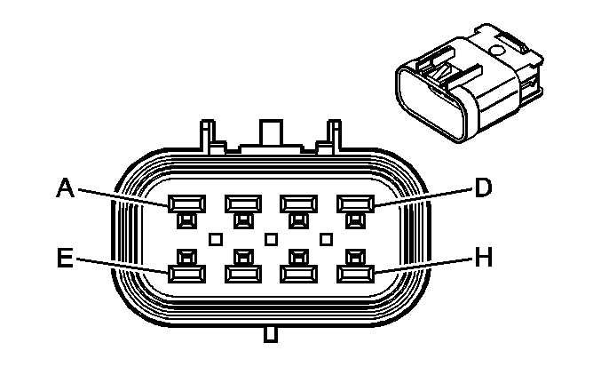
|
Connector Part Information
| Connector Part Information
|
Terminal Part Information
| Terminal Part Information
|
Pin | Wire Color | Circuit No. | Function | Pin | Wire Color | Circuit No. | Function |
|---|---|---|---|---|---|---|---|
A | PU/WH | 1668 | HO2S High Signal - Bank 1 Sensor 2 | A | PU/WH | 1668 | HO2S High Signal - Bank 1 Sensor 2 |
B | PK | 1539 | Ignition 1 Voltage | B | PK | 1539 | Ignition 1 Voltage |
C | TN/WH | 1669 | HO2S Low Signal - Bank 1 Sensor 2 | C | TN/WH | 1669 | HO2S Low Signal - Bank 1 Sensor 2 |
D | TN | 1671 | HO2S Low Signal - Bank 2 Sensor 2 | D | TN | 1671 | HO2S Low Signal - Bank 2 Sensor 2 |
E | PU | 1670 | HO2S High Signal - Bank 2 Sensor 2 | E | PU | 1670 | HO2S High Signal - Bank 2 Sensor 2 |
F | PK | 1539 | Ignition 1 Voltage | F | PK | 1539 | Ignition 1 Voltage |
G | PU | 5035 | HO2S Heater Low Control - Bank 1 Sensor 2 | G | PU | 5035 | HO2S Heater Low Control - Bank 1 Sensor 2 |
H | YE | 5036 | HO2S Heater Low Control - Bank 2 Sensor 2 | H | YE | 5036 | HO2S Heater Low Control - Bank 2 Sensor 2 |
C141 I/P Harness to Brake Fluid Level Harness (UJ1)
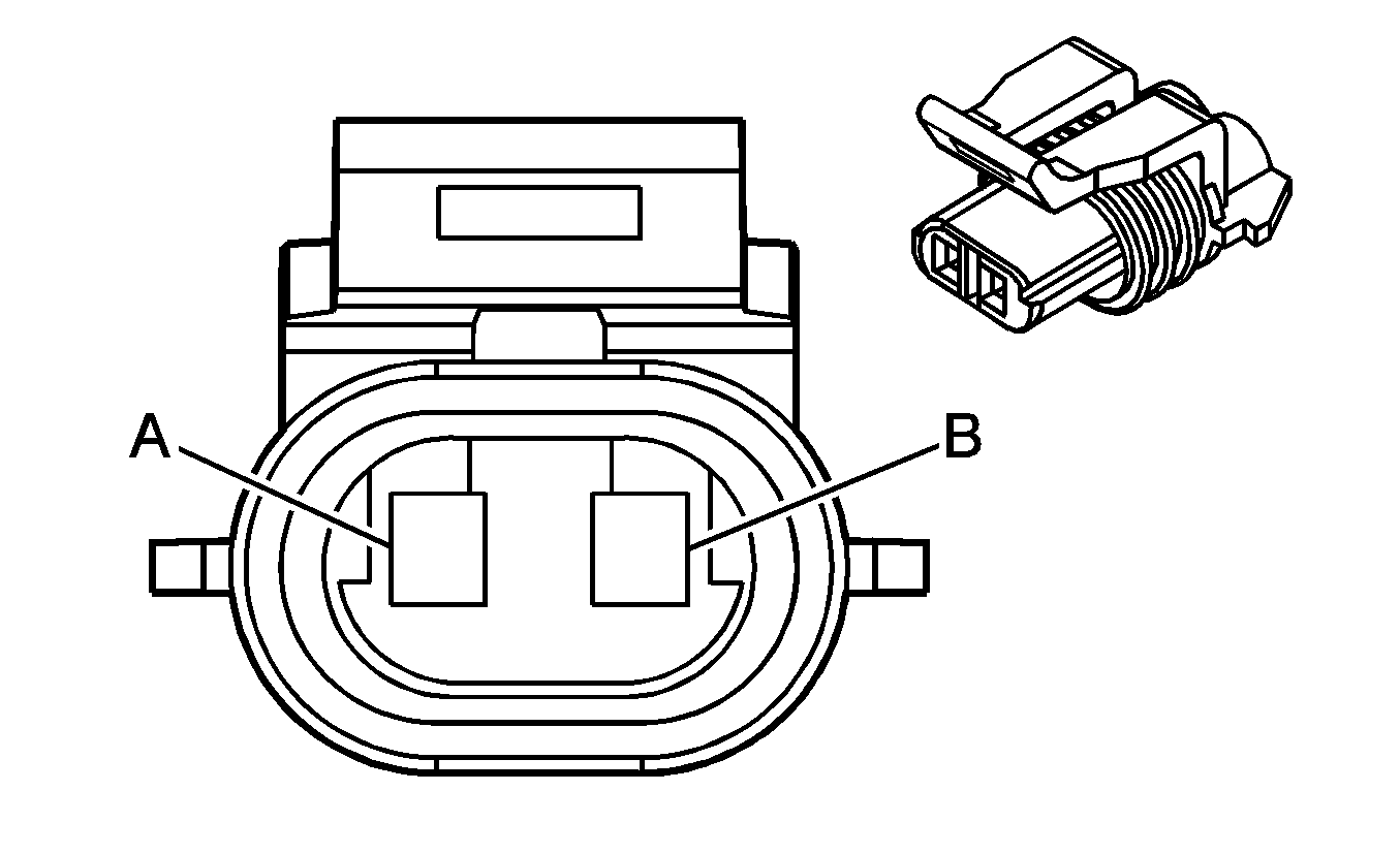
|
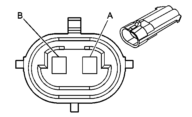
|
Connector Part Information
| Connector Part Information
|
Terminal Part Information
| Terminal Part Information
|
Pin | Wire Color | Circuit No. | Function | Pin | Wire Color | Circuit No. | Function |
|---|---|---|---|---|---|---|---|
A | TN/WH | 33 | Brake Booster Fluid Switch Signal | A | TN/WH | 33 | Brake Booster Fluid Switch Signal |
B | BK | 350 | Ground | B | BK | 350 | Ground |
C174 Chassis Harness to Transmission Harness (Diesel)

|

|
Connector Part Information
| Connector Part Information
|
Terminal Part Information
| Terminal Part Information
|
Pin | Wire Color | Circuit No. | Function | Pin | Wire Color | Circuit No. | Function |
|---|---|---|---|---|---|---|---|
A1 | PK | 139 | Ignition 1 Voltage | A1 | PK | 139 | Ignition 1 Voltage |
A2 | D-GN | 1433 | PNP Start Switch Signal | A2 | D-GN | 1433 | PNP Start Switch Signal |
A3 | PK | 339 | Ignition 1 Voltage | A3 | PK | 339 | Ignition 1 Voltage |
A4 | BK | 150 | Ground | A4 | BK | 150 | Ground |
A5 | YE | 400 | VSS High Signal | A5 | YE | 400 | VSS High Signal |
B1 | PU | 401 | VSS Low Signal | B1 | PU | 401 | VSS Low Signal |
B2 | OG/BK | 1786 | Park/Neutral Signal | B2 | OG/BK | 1786 | Park/Neutral Signal |
B3 | D-GN | 1324 | Backup Lamp Supply Voltage | B3 | D-GN | 1324 | Backup Lamp Supply Voltage |
B4 | L-GN | 275 | Park Neutral Position Switch Park Signal | B4 | L-GN | 275 | Park Neutral Position Switch Park Signal |
B5 | OG/BK | 1230 | A/T ISS High Signal | B5 | OG/BK | 1230 | A/T ISS High Signal |
B6 | D-BU/WH | 1231 | A/T ISS Low Signal | B6 | D-BU/WH | 1231 | A/T ISS Low Signal |
B7 | TN/WH | 771 | Transmission Range Switch Signal A | B7 | TN/WH | 771 | Transmission Range Switch Signal A |
B8 | YE | 772 | Transmission Range Switch Signal B | B8 | YE | 772 | Transmission Range Switch Signal B |
B9 | GY | 773 | Transmission Range Switch Signal C | B9 | GY | 773 | Transmission Range Switch Signal C |
B10 | WH | 776 | Transmission Range Switch Signal P | B10 | WH | 776 | Transmission Range Switch Signal P |
C1 | L-GN | 1222 | 1-2 Shift Solenoid Valve Control | C1 | L-GN | 1222 | 1-2 Shift Solenoid Valve Control |
C2 | YE/BK | 1223 | 2-3 Shift Solenoid Valve Control | C2 | YE/BK | 1223 | 2-3 Shift Solenoid Valve Control |
C3 | BN | 418 | TCC PWM Solenoid Valve Control | C3 | BN | 418 | TCC PWM Solenoid Valve Control |
C4 | OG/BK | 1228 | PC Solenoid Valve High Control | C4 | OG/BK | 1228 | PC Solenoid Valve High Control |
C5 | L-BU/WH | 1229 | PC Solenoid Valve Low Control | C5 | L-BU/WH | 1229 | PC Solenoid Valve Low Control |
C6 | YE/BK | 1227 | TFT Sensor Signal | C6 | YE/BK | 1227 | TFT Sensor Signal |
C7 | TN | 2762 | Low Reference | C7 | TN | 2762 | Low Reference |
C8 | PK | 1224 | Transmission Fluid Pressure Switch Signal A | C8 | PK | 1224 | Transmission Fluid Pressure Switch Signal A |
C9 | D-BU | 1225 | Transmission Fluid Pressure Switch Signal B | C9 | D-BU | 1225 | Transmission Fluid Pressure Switch Signal B |
C10 | OG | 1226 | Transmission Fluid Pressure Switch Signal C | C10 | OG | 1226 | Transmission Fluid Pressure Switch Signal C |
D1 | PK | 1020 | Ignition 0 Voltage | D1 | PK | 1020 | Ignition 0 Voltage |
D2 | D-BU | 6863 | Low Reference | D2 | D-BU | 6863 | Low Reference |
D3 | PK | 1739 | Ignition 1 Voltage | D3 | PK | 1739 | Ignition 1 Voltage |
D4 | L-GN | 1058 | Fuel Pump Supply Voltage | D4 | L-GN | 1058 | Fuel Pump Supply Voltage |
D5 | YE/BK | 508 | Water In Fuel Indicator Control | D5 | YE/BK | 508 | Water In Fuel Indicator Control |
C175 Engine Harness to Transmission (4L60-E)
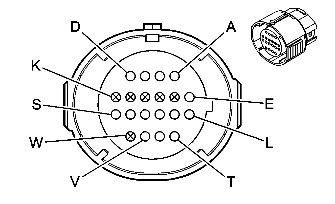
|
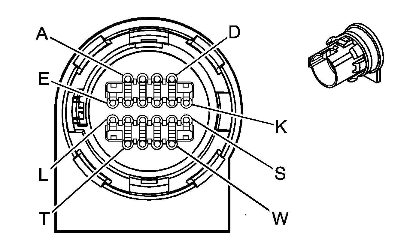
|
Connector Part Information
| Connector Part Information
|
Terminal Part Information
| Terminal Part Information
|
Pin | Wire Color | Circuit No. | Function | Pin | Wire Color | Circuit No. | Function |
|---|---|---|---|---|---|---|---|
A | L-GN | 1222 | 1-2 Shift Solenoid Valve Control | A | L-GN | 1222 | 1-2 Shift Solenoid Valve Control |
B | YE/BK | 1223 | 2-3 Shift Solenoid Valve Control | B | YE | 1223 | 2-3 Shift Solenoid Valve Control |
C | OG/BK | 1228 | PC Solenoid Valve High Control | C | PU | 1228 | PC Solenoid Valve High Control |
D | L-BU/WH | 1229 | PC Solenoid Valve Low Control | D | L-BU | 1229 | PC Solenoid Valve Low Control |
E | PK | 1020 | Ignition 0 Voltage | E | RD | 839 | Ignition 1 Voltage |
F-K | -- | -- | Not Used | F-K | -- | -- | Not Used |
L | YE/BK | 1227 | TFT Sensor Signal | L | BN | 1227 | TFT Sensor Signal |
M | TN | 2762 | Low Reference | M | GY | 452 | Low Reference |
N | PK | 1224 | Transmission Fluid Pressure Switch Signal A | N | PK | 1224 | Transmission Fluid Pressure Switch Signal A |
P | OG | 1226 | Transmission Fluid Pressure Switch Signal C | P | OG | 1226 | Transmission Fluid Pressure Switch Signal C |
R | D-BU | 1225 | Transmission Fluid Pressure Switch Signal B | R | D-BU | 1225 | Transmission Fluid Pressure Switch Signal B |
S | WH | 687 | 3-2 Shift Solenoid Valve Control | S | WH | 687 | 3-2 Shift Solenoid Valve Control |
T | TN/BK | 422 | TCC Solenoid Valve Control | T | BK | 422 | TCC Solenoid Valve Control |
U | BN | 418 | TCC PWM Solenoid Valve Control | U | TN | 418 | TCC PWM Solenoid Valve Control |
V-W | -- | -- | Not Used | V-W | -- | -- | Not Used |
C175 Engine Harness to Transmission - Gas or Transmission Harness to Transmission - Diesel (4L80-E/4L85-E)

|

|
Connector Part Information
| Connector Part Information
|
Terminal Part Information
| Terminal Part Information
|
Pin | Wire Color | Circuit No. | Function | Pin | Wire Color | Circuit No. | Function |
|---|---|---|---|---|---|---|---|
A | L-GN | 1222 | 1-2 Shift Solenoid Valve Control | A | L-GN | 1222 | 1-2 Shift Solenoid Valve Control |
B | YE/BK | 1223 | 2-3 Shift Solenoid Valve Control | B | YE | 1223 | 2-3 Shift Solenoid Valve Control |
C | OG/BK | 1228 | PC Solenoid Valve High Control | C | PU | 1228 | PC Solenoid Valve High Control |
D | L-BU/WH | 1229 | PC Solenoid Valve Low Control | D | L-BU | 1229 | PC Solenoid Valve Low Control |
E | PK | 1020 | Ignition 0 Voltage | E | RD | 839 | Ignition 1 Voltage |
F-K | -- | -- | Not Used | F-K | -- | -- | Not Used |
L | YE/BK | 1227 | TFT Sensor Signal | L | BN | 1227 | TFT Sensor Signal |
M | TN | 2762 | Low Reference | M | GY | 452 | Low Reference |
N | PK | 1224 | Transmission Fluid Pressure Switch Signal A | N | PK | 1224 | Transmission Fluid Pressure Switch Signal A |
P | OG | 1226 | Transmission Fluid Pressure Switch Signal C | P | OG | 1226 | Transmission Fluid Pressure Switch Signal C |
R | D-BU | 1225 | Transmission Fluid Pressure Switch Signal B | R | D-BU | 1225 | Transmission Fluid Pressure Switch Signal B |
S | BN | 418 | TCC PWM Solenoid Valve Control | S | BK | 418 | TCC PWM Solenoid Valve Control |
T-W | -- | -- | Not Used | T-W | -- | -- | Not Used |
C200 Steering Column Harness to I/P Harness
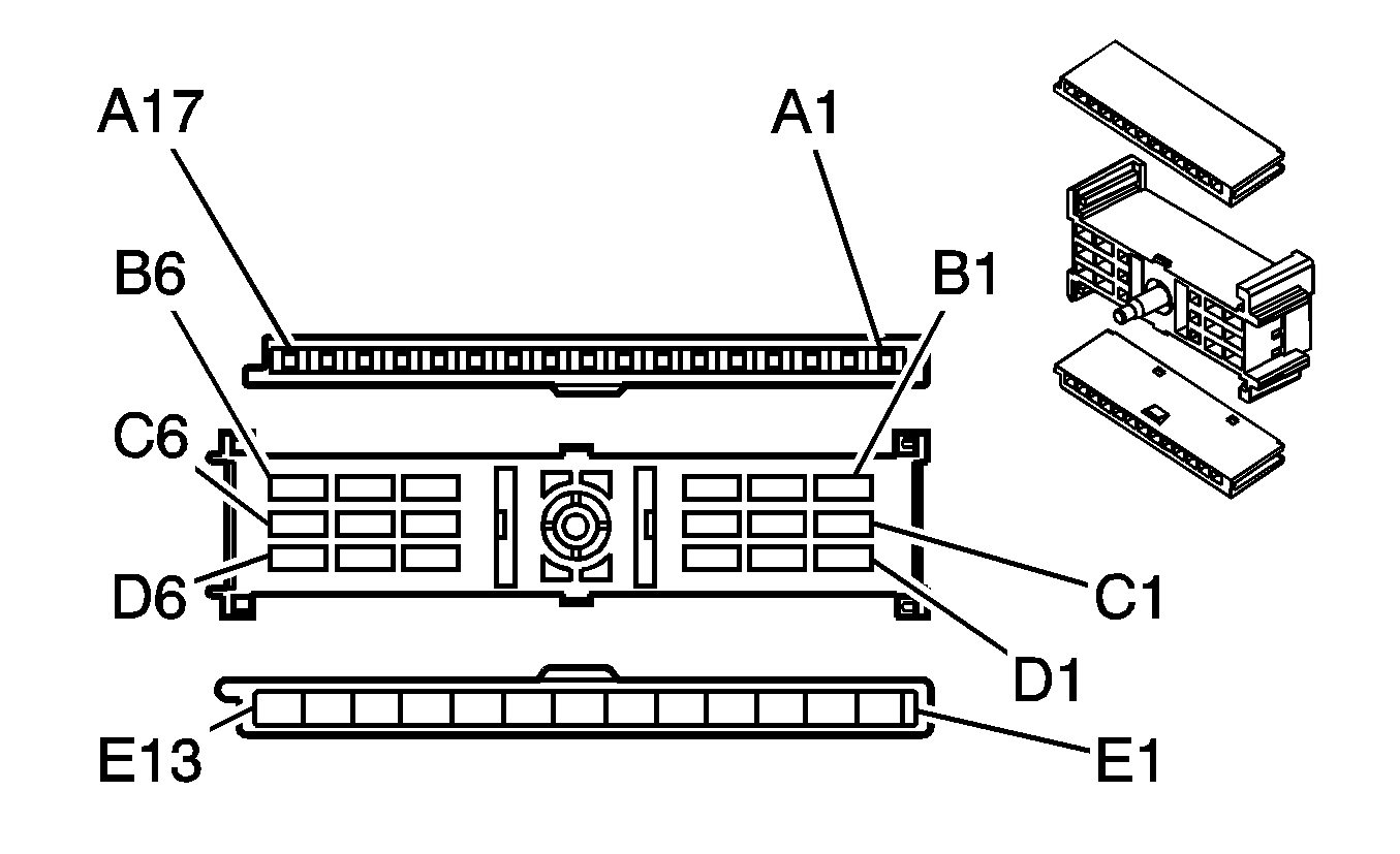
|
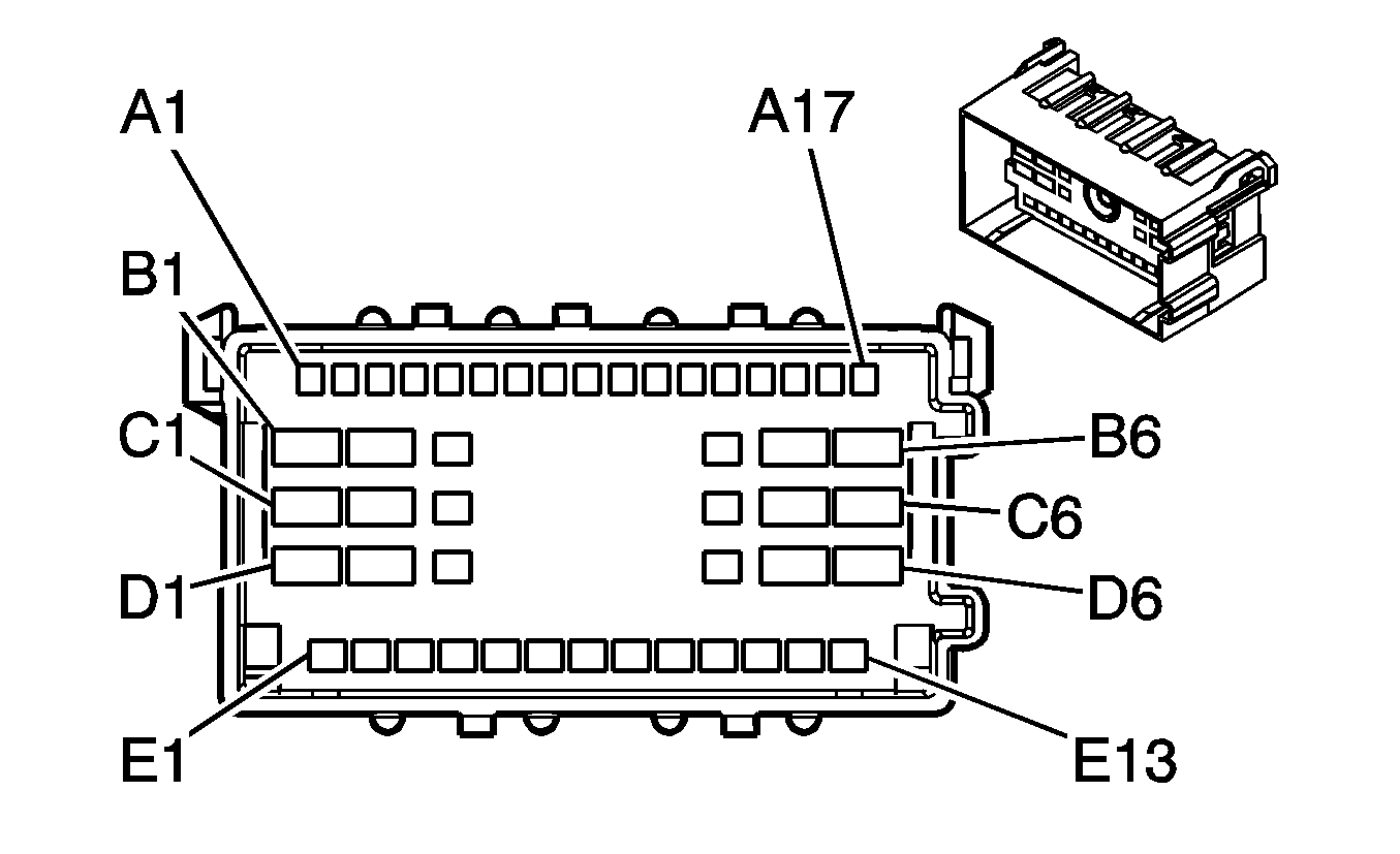
|
Connector Part Information
| Connector Part Information
|
Terminal Part Information
| Terminal Part Information
|
Pin | Wire Color | Circuit No. | Function | Pin | Wire Color | Circuit No. | Function |
|---|---|---|---|---|---|---|---|
A1 | TN | 28 | Horn Relay Control | A1 | TN | 28 | Horn Relay Control |
A2-A3 | -- | -- | Not Used | A2-A3 | -- | -- | Not Used |
A4 | D-BU/WH | 1415 | Right Turn Signal Switch Signal | A4 | D-BU/WH | 1415 | Right Turn Signal Switch Signal |
A5 | L-BU/WH | 1414 | Left Turn Signal Switch Signal | A5 | L-BU/WH | 1414 | Left Turn Signal Switch Signal |
A6-A10 | -- | -- | Not Used | A6-A10 | -- | -- | Not Used |
A11 | L-GN | 80 | Key In Ignition Switch Signal | A11 | L-GN | 80 | Key In Ignition Switch Signal |
A12-A17 | -- | -- | Not Used | A12-A17 | -- | -- | Not Used |
B1-B3 | -- | -- | Not Used | B1-B3 | -- | -- | Not Used |
B4 | WH | 111 | Hazard Switch Signal | B4 | WH | 111 | Hazard Switch Signal |
WH | 111 | Hazard Switch Signal | |||||
B5 | RD/BK | 142 | Battery Positive Voltage | B5 | RD/BK | 142 | Battery Positive Voltage |
B6 | BN | 4 | Accessory Voltage | B6 | BN | 4 | Accessory Voltage |
C1 | YE | 5 | Crank Voltage | C1 | YE | 5 | Crank Voltage |
C2 | -- | -- | Not Used | C2 | -- | -- | Not Used |
C3 | OG/WH | 812 | 12-Volt Reference | C3 | OG/WH | 812 | 12-Volt Reference |
C4 | TN | 1835 | Security System Sensor Low Reference | C4 | TN | 1835 | Security System Sensor Low Reference |
C5 | WH | 1390 | Accy/Run/Start Voltage | C5 | WH | 1390 | Accy/Run/Start Voltage |
C6 | PK | 3 | Ignition 1 Voltage | C6 | PK | 3 | Ignition 1 Voltage |
D1 | OG | 300 | Ignition 3 Voltage | D1 | OG | 300 | Ignition 3 Voltage |
D2 | RD/BK | 342 | Battery Positive Voltage | D2 | RD/BK | 342 | Battery Positive Voltage |
D3 | YE | 1836 | Security System Sensor Signal | D3 | YE | 1836 | Security System Sensor Signal |
D4-D6 | -- | -- | Not Used | D4-D6 | -- | -- | Not Used |
E1 | BK | 350 | Ground | E1 | BK | 350 | Ground |
E2 | -- | -- | Not Used | E2 | -- | -- | Not Used |
E3 | GY/BK | 87 | Cruise Control Resume/Accel Switch Signal (K34) | E3 | GY/BK | 87 | Cruise Control Resume/Accel Switch Signal (K34) |
E4 | PK | 94 | Windshield Washer Switch Signal 1 | E4 | PK | 94 | Windshield Washer Switch Signal 1 |
E5 | D-BU | 477 | Windshield Wiper Switch High Signal | E5 | D-BU | 477 | Windshield Wiper Switch High Signal |
E6 | -- | -- | Not Used | E6 | -- | -- | Not Used |
E7 | D-GN/WH | 1135 | A/T Shift Lock Control Solenoid Supply Voltage | E7 | D-GN/WH | 1135 | A/T Shift Lock Control Solenoid Supply Voltage |
E8 | GY | 478 | Windshield Wiper Switch Supply Voltage | E8 | GY | 478 | Windshield Wiper Switch Supply Voltage |
E9 | GY | 397 | Cruise Control On Switch Signal (K34) | E9 | GY | 397 | Cruise Control On Switch Signal (K34) |
E10 | D-BU | 84 | Cruise Control Set/Coast Switch Signal (K34) | E10 | D-BU | 84 | Cruise Control Set/Coast Switch Signal (K34) |
E11 | YE | 307 | Headlamp Switch Flash to Pass Signal | E11 | YE | 307 | Headlamp Switch Flash to Pass Signal |
E12 | L-GN | 11 | Headlamp Dimmer Switch Signal | E12 | L-GN | 11 | Headlamp Dimmer Switch Signal |
E13 | PK | 739 | Ignition 1 Voltage | E13 | PK | 739 | Ignition 1 Voltage |
PK | 739 | Ignition 1 Voltage (K34) |
C203 Vanity Lamp Harness to Body Harness (YF7/DH6)
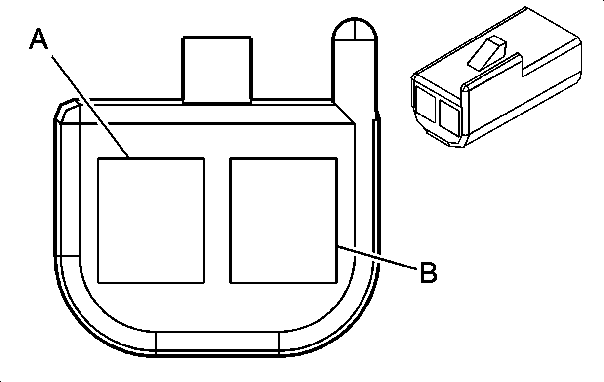
|
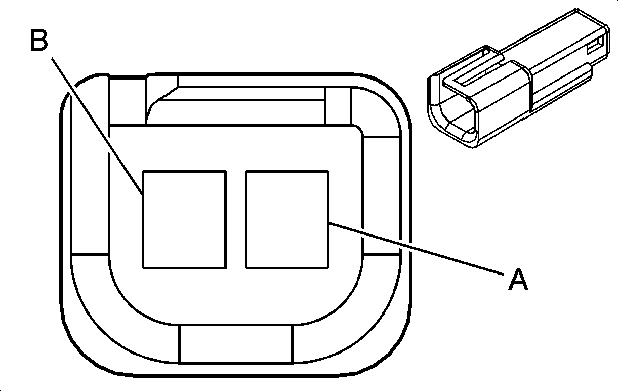
|
Connector Part Information
| Connector Part Information
|
Terminal Part Information
| Terminal Part Information
|
Pin | Wire Color | Circuit No. | Function | Pin | Wire Color | Circuit No. | Function |
|---|---|---|---|---|---|---|---|
A | OG | 1732 | Inadvertent Power Supply Voltage | A | OG | 1732 | Inadvertent Power Supply Voltage |
B | BK | 450 | Ground | B | BK | 450 | Ground |
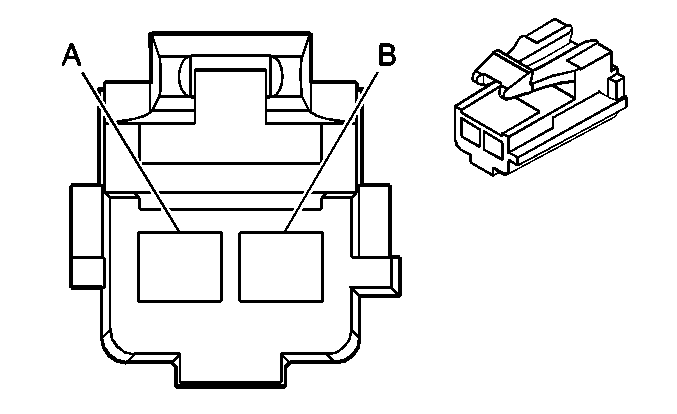
C220 I/P Harness to Parking Brake Harness
|
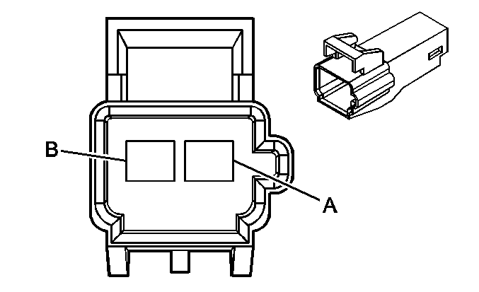
|
Connector Part Information
| Connector Part Information
|
Terminal Part Information
| Terminal Part Information
|
Pin | Wire Color | Circuit No. | Function | Pin | Wire Color | Circuit No. | Function |
|---|---|---|---|---|---|---|---|
A | L-BU | 1134 | Park Brake Switch Signal | A | L-BU | 1134 | Park Brake Switch Signal |
B | -- | -- | Not Used | B | -- | -- | Not Used |
C221 Brake Switch Harness to I/P Harness
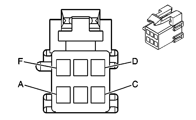
|
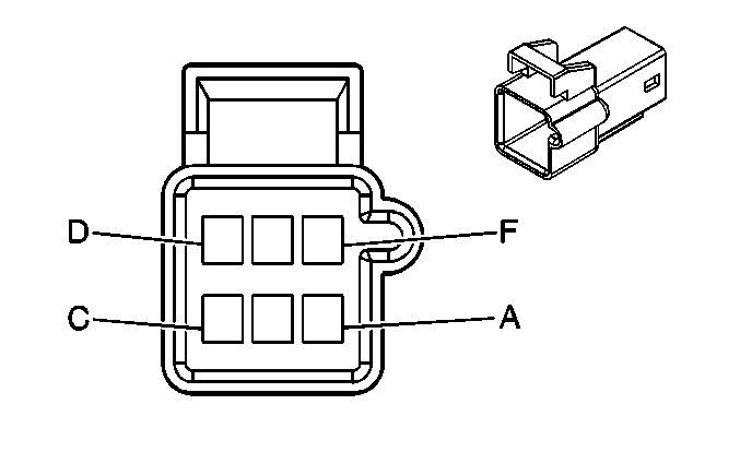
|
Connector Part Information
| Connector Part Information
|
Terminal Part Information
| Terminal Part Information
|
Pin | Wire Color | Circuit No. | Function | Pin | Wire Color | Circuit No. | Function |
|---|---|---|---|---|---|---|---|
A | WH | 17 | Stop Lamp Switch Signal | A | WH | 17 | Stop Lamp Switch Signal |
B | RD/WH | 1540 | Battery Positive Voltage | B | RD/WH | 1540 | Battery Positive Voltage |
C | PK | 739 | Ignition 1 Voltage | C | PK | 739 | Ignition 1 Voltage |
D | PU | 420 | TCC Brake Switch/Cruise Control Release Signal | D | PU | 420 | TCC Brake Switch/Cruise Control Release Signal |
E | L-GN/BK | 584 | A/T Shift Lock Control Switch Supply Voltage | E | L-GN/BK | 584 | A/T Shift Lock Control Switch Supply Voltage |
F | D-GN/WH | 1135 | A/T Shift Lock Control Solenoid Supply Voltage | F | D-GN/WH | 1135 | A/T Shift Lock Control Solenoid Supply Voltage |
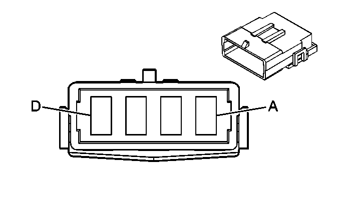
C222 Upfitter Harness to I/P Harness (YF7)
-- |
|
Connector Part Information
| Connector Part Information
|
Terminal Part Information
| Terminal Part Information
|
Pin | Wire Color | Circuit No. | Function | Pin | Wire Color | Circuit No. | Function |
|---|---|---|---|---|---|---|---|
A | -- | -- | Upfitter Usage | A | RD/BK | 1042 | Battery Positive Voltage |
B | -- | -- | Upfitter Usage | B | BN | 541 | Ignition 3 Voltage |
C | -- | -- | Upfitter Usage | C | BK | 350 | Ground |
D | -- | -- | Upfitter Usage | D | -- | -- | Not Used |
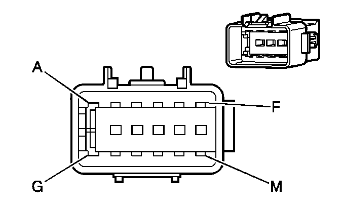
C225 I/P Harness to Mirror Harness (DF5)
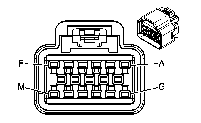
|
|
Connector Part Information
| Connector Part Information
|
Terminal Part Information
| Terminal Part Information
|
Pin | Wire Color | Circuit No. | Function | Pin | Wire Color | Circuit No. | Function |
|---|---|---|---|---|---|---|---|
A | PK | 1439 | Ignition 1 Voltage | A | PK | 1439 | Ignition 1 Voltage |
B | L-GN | 24 | Backup Lamp Supply Voltage | B | L-GN | 24 | Backup Lamp Supply Voltage |
C-E | -- | -- | Not Used | C-E | -- | -- | Not Used |
F | D-GN/WH | 636 | Ambient Air Temperature Sensor Signal | F | D-GN/WH | 636 | Ambient Air Temperature Sensor Signal |
G | TN/WH | 1704 | Low Reference | G | TN/WH | 1704 | Low Reference |
H-K | -- | -- | Not Used | H-K | -- | -- | Not Used |
L | BK | 550 | Ground | L | BK | 550 | Ground |
M | -- | -- | Not Used | M | -- | -- | Not Used |
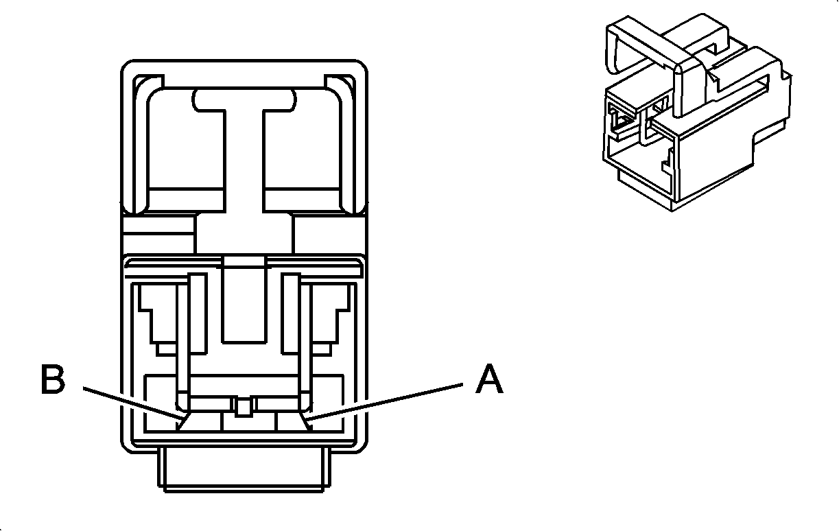
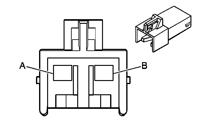
C275 SIR Coil to I/P Harness (Heavy Duty)
|
|
Connector Part Information
| Connector Part Information
|
Terminal Part Information
| Terminal Part Information
|
Pin | Wire Color | Circuit No. | Function | Pin | Wire Color | Circuit No. | Function |
|---|---|---|---|---|---|---|---|
A | WH | 3021 | Steering Wheel Module - Stage 1 - High Control | A | TN | 3021 | Steering Wheel Module - Stage 1 - High Control |
B | D-GN | 3020 | Steering Wheel Module - Stage 1 - Low Control | B | BN | 3020 | Steering Wheel Module - Stage 1 - Low Control |
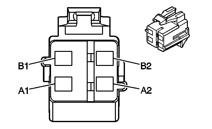
C275 SIR Coil to I/P Harness (Light Duty)
|
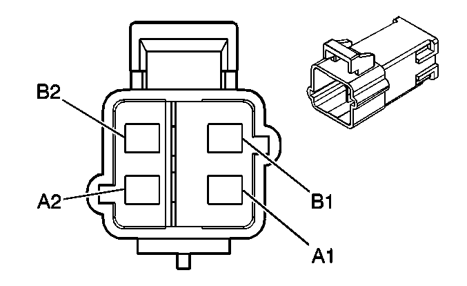
|
Connector Part Information
| Connector Part Information
|
Terminal Part Information
| Terminal Part Information
|
Pin | Wire Color | Circuit No. | Function | Pin | Wire Color | Circuit No. | Function |
|---|---|---|---|---|---|---|---|
A1 | TN | 3021 | Steering Wheel Module - Stage 1 - High Control | A1 | TN | 3021 | Steering Wheel Module - Stage 1 - High Control |
A2 | BN | 3020 | Steering Wheel Module - Stage 1 - Low Control | A2 | BN | 3020 | Steering Wheel Module - Stage 1 - Low Control |
B1 | WH | 3023 | Steering Wheel Module - Stage 2 - High Control | B1 | WH | 3023 | Steering Wheel Module - Stage 2 - High Control |
B2 | PK | 3022 | Steering Wheel Module - Stage 2 - Low Control | B2 | PK | 3022 | Steering Wheel Module - Stage 2 - Low Control |
C300 I/P Harness to Body Harness (Light Duty)
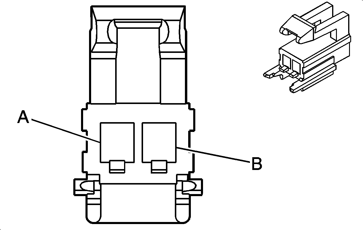
|
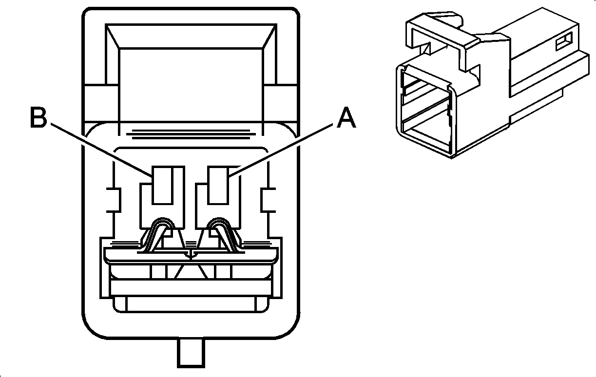
|
Connector Part Information
| Connector Part Information
|
Terminal Part Information
| Terminal Part Information
|
Pin | Wire Color | Circuit No. | Function | Pin | Wire Color | Circuit No. | Function |
|---|---|---|---|---|---|---|---|
A | L-GN | 2116 | Seat Belt Pretensioner - Right - High Control | A | L-GN | 2116 | Seat Belt Pretensioner - Right - High Control |
B | OG | 2117 | Seat Belt Pretensioner - Right - Low Control | B | OG | 2117 | Seat Belt Pretensioner - Right - Low Control |
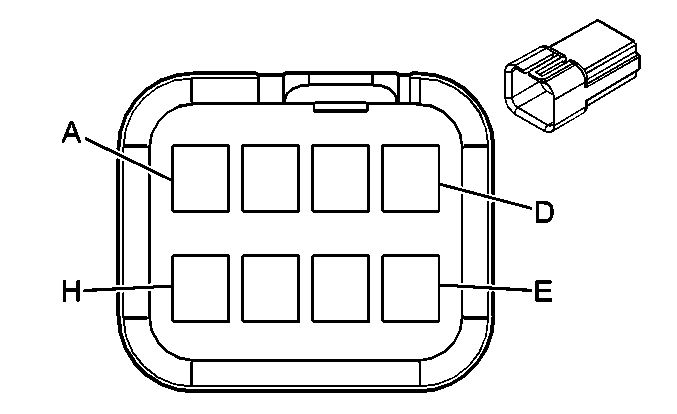
C303 Upfitter Harness to Body Harness (YF7 w/Rear Auxiliary Controls)
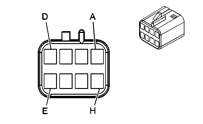
|
|
Connector Part Information
| Connector Part Information
|
Terminal Part Information
| Terminal Part Information
|
Pin | Wire Color | Circuit No. | Function | Pin | Wire Color | Circuit No. | Function |
|---|---|---|---|---|---|---|---|
A | WH | 1924 | Auxiliary Blower Motor High Control | A | WH | 1924 | Auxiliary Blower Motor High Control |
B | OG | 1925 | Auxiliary Blower Motor Medium Control | B | OG | 1925 | Auxiliary Blower Motor Medium Control |
C | D-BU | 1926 | Auxiliary Blower Motor Low Control | C | D-BU | 1926 | Auxiliary Blower Motor Low Control |
D | OG | 2775 | Auxiliary Air Temperature Door Control | D | OG | 2775 | Auxiliary Air Temperature Door Control |
E | GY | 2599 | Auxiliary Mode Door Control | E | GY | 2599 | Auxiliary Mode Door Control |
F | BN/WH | 230 | Instrument Panel Lamps Dimming Control | F | BN/WH | 230 | Instrument Panel Lamps Dimming Control |
G | BN | 341 | Ignition 3 Voltage | G | BN | 341 | Ignition 3 Voltage |
H | BK | 450 | Ground | H | BK | 450 | Ground |
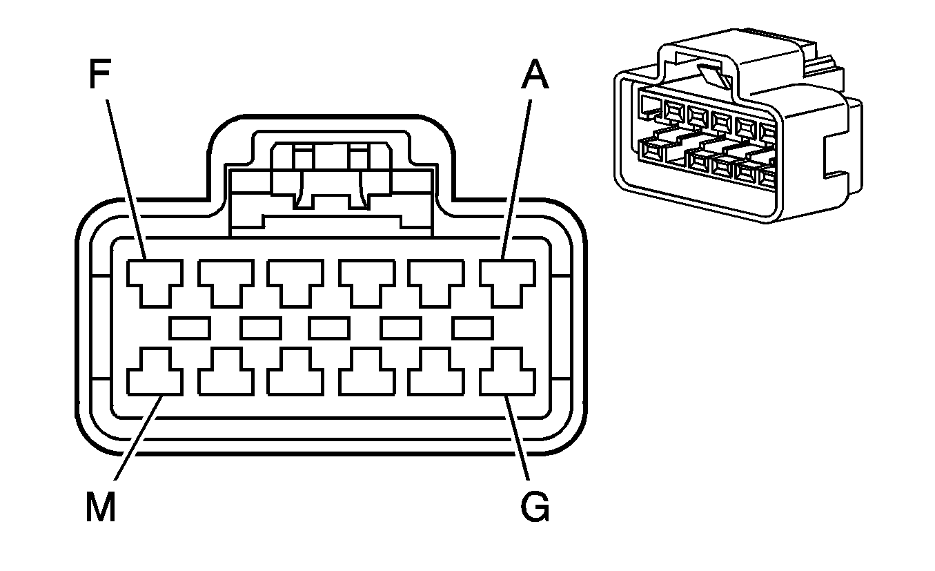
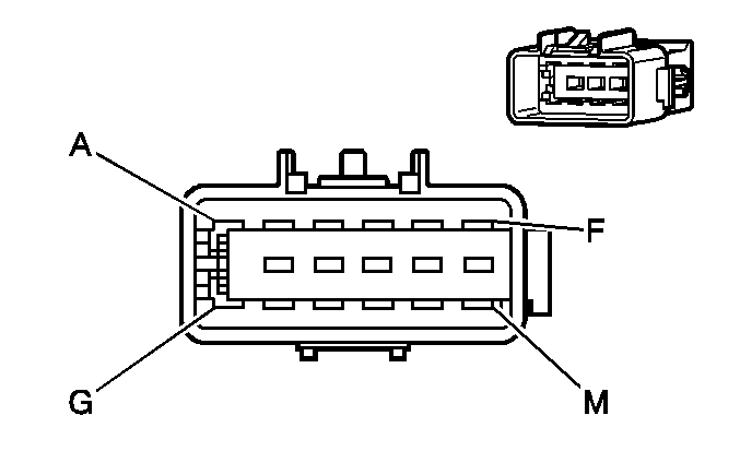
C304 Headliner Harness to Body Harness (w/o YF7)
|
|
Connector Part Information
| Connector Part Information
|
Terminal Part Information
| Terminal Part Information
|
Pin | Wire Color | Circuit No. | Function | Pin | Wire Color | Circuit No. | Function |
|---|---|---|---|---|---|---|---|
A | BN | 341 | Ignition 3 Voltage (C69) | A | BN | 341 | Ignition 3 Voltage (C69) |
B | BN/WH | 230 | Instrument Panel Lamps Dimming Control (C69) | B | BN/WH | 230 | Instrument Panel Lamps Dimming Control (C69) |
C | BK | 450 | Ground | C | BK | 450 | Ground |
D | OG | 2775 | Auxiliary Air Temperature Door Control (C69) | D | OG | 2775 | Auxiliary Air Temperature Door Control (C69) |
E | GY | 2599 | Auxiliary Mode Door Control (C69) | E | GY | 2599 | Auxiliary Mode Door Control (C69) |
F | D-BU/WH | 149 | Courtesy Lamp Supply Voltage | F | D-BU/WH | 149 | Courtesy Lamp Supply Voltage |
G | OG | 1732 | Inadvertent Power Supply Voltage | G | OG | 1732 | Inadvertent Power Supply Voltage |
H | WH | 1924 | Auxiliary Blower Motor High Control (Rear Auxiliary Controls) | H | WH | 1924 | Auxiliary Blower Motor High Control (Rear Auxiliary Controls) |
J | OG | 1925 | Auxiliary Blower Motor Medium Control (Rear Auxiliary Controls) | J | OG | 1925 | Auxiliary Blower Motor Medium Control (Rear Auxiliary Controls) |
K | D-BU | 1926 | Auxiliary Blower Motor Low Control (Rear Auxiliary Controls) | K | D-BU | 1926 | Auxiliary Blower Motor Low Control (Rear Auxiliary Controls) |
L-M | -- | -- | Not Used | L-M | -- | -- | Not Used |
C305 Chassis Harness to Coolant Heater Fuel Pump Jumper Harness (K08)

|

|
Connector Part Information
| Connector Part Information
|
Terminal Part Information
| Terminal Part Information
|
Pin | Wire Color | Circuit No. | Function | Pin | Wire Color | Circuit No. | Function |
|---|---|---|---|---|---|---|---|
A | D-BU/GN | 7077 | Coolant Heater - Fuel Pump Control | A | GN/RD | 7077 | Coolant Heater - Fuel Pump Control |
B | BK | 150 | Ground | B | BN | 150 | Ground |
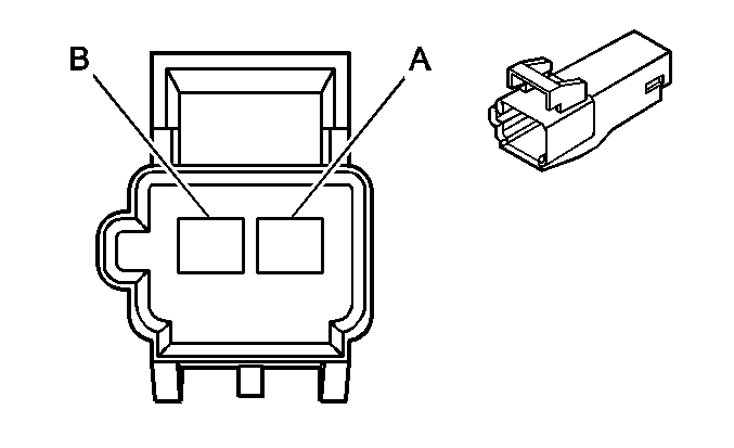
C306 Body Harness to Front Passenger Seat Harness (Heavy Duty w/AG1/AG2)

|
|
Connector Part Information
| Connector Part Information
|
Terminal Part Information
| Terminal Part Information
|
Pin | Wire Color | Circuit No. | Function | Pin | Wire Color | Circuit No. | Function |
|---|---|---|---|---|---|---|---|
A | BK | 450 | Ground | A | BK | 450 | Ground (AG2) |
B | RD/WH | 3540 | Battery Positive Voltage | B | RD/WH | 3540 | Battery Positive Voltage (AG2) |
C306 Body Harness to Front Passenger Seat Harness (Light Duty)

|

|
Connector Part Information
| Connector Part Information
|
Terminal Part Information
| Terminal Part Information
|
Pin | Wire Color | Circuit No. | Function | Pin | Wire Color | Circuit No. | Function |
|---|---|---|---|---|---|---|---|
A | PK | 1139 | Ignition 1 Voltage (w/o YF7) | A | PK | 1139 | Ignition 1 Voltage (w/o YF7) |
B | PK | 5018 | Occupant Sensor - Serial Data (w/o YF7) | B | PK | 5018 | Occupant Sensor - Serial Data (w/o YF7) |
C | D-BU | 2307 | Passenger Air Bag On Indicator Control (w/o YF7) | C | D-BU | 2307 | Passenger Air Bag On Indicator Control (w/o YF7) |
D | BK/WH | 351 | Ground (w/o YF7) | D | BK/WH | 351 | Ground (w/o YF7) |
E | D-GN | 2308 | Passenger Air Bag Off Indicator Control (w/o YF7) | E | D-GN | 2308 | Passenger Air Bag Off Indicator Control (w/o YF7) |
F | TN/WH | 1362 | Passenger Seat Belt Switch Signal | F | TN/WH | 1362 | Passenger Seat Belt Switch Signal |
G | PK | 5017 | Low Reference | G | PK | 5017 | Low Reference |
H | L-BU | 5056 | Seat Position Sensor - Right - Signal | H | L-BU | 5056 | Seat Position Sensor - Right - Signal |
J | BK | 450 | Ground | J | BK | 450 | Ground |
K | RD/WH | 3540 | Battery Positive Voltage (AG1/AG2) | K | RD/WH | 3540 | Battery Positive Voltage (AG2) |
L-M | -- | -- | Not Used | L-M | -- | -- | Not Used |
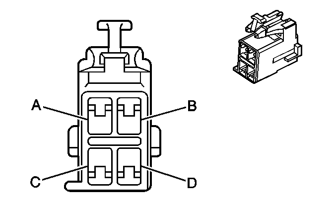
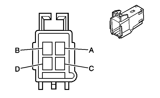
C307 Body Harness to Driver Seat Harness (Heavy Duty)
|
|
Connector Part Information
| Connector Part Information
|
Terminal Part Information
| Terminal Part Information
|
Pin | Wire Color | Circuit No. | Function | Pin | Wire Color | Circuit No. | Function |
|---|---|---|---|---|---|---|---|
A | -- | -- | Not Used | A | -- | -- | Not Used |
B | TN/WH | 238 | Driver Seat Belt Switch Signal | B | TN/WH | 238 | Driver Seat Belt Switch Signal |
C | BK | 450 | Ground | C | BK | 450 | Ground |
D | RD/WH | 3540 | Battery Positive Voltage (AG1/AG2) | D | RD/WH | 3540 | Battery Positive Voltage (AG1) |
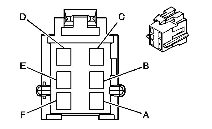
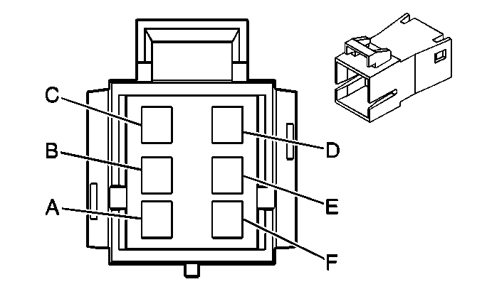
C307 Body Harness to Driver Seat Harness (Light Duty)
|
|
Connector Part Information
| Connector Part Information
|
Terminal Part Information
| Terminal Part Information
|
Pin | Wire Color | Circuit No. | Function | Pin | Wire Color | Circuit No. | Function |
|---|---|---|---|---|---|---|---|
A | L-GN | 5055 | Seat Position Sensor - Left - Signal | A | L-GN | 5055 | Seat Position Sensor - Left - Signal |
B | PK | 5017 | Low Reference | B | PK | 5017 | Low Reference |
C | TN/WH | 238 | Driver Seat Belt Switch Signal | C | TN/WH | 238 | Driver Seat Belt Switch Signal |
D | BK | 450 | Ground | D | BK | 450 | Ground |
E | RD/WH | 3540 | Battery Positive Voltage (AG1/AG2) | E | RD/WH | 3540 | Battery Positive Voltage (AG1) |
F | -- | -- | Not Used | F | -- | -- | Not Used |
C311 Driver Door Harness to Body Harness
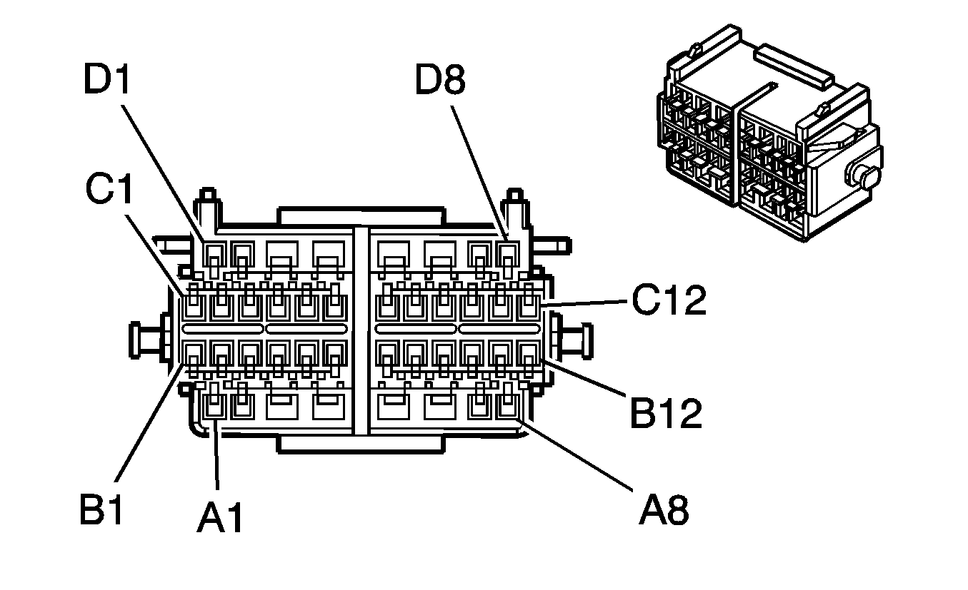
|
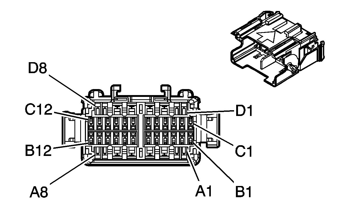
|
Connector Part Information
| Connector Part Information
|
Terminal Part Information
| Terminal Part Information
|
Pin | Wire Color | Circuit No. | Function | Pin | Wire Color | Circuit No. | Function |
|---|---|---|---|---|---|---|---|
A1 | TN | 126 | Left Front Door Open Switch Signal | A1 | TN | 126 | Left Front Door Open Switch Signal |
A2 | L-BU | 1957 | Left Front Midrange Speaker Output (-) | A2 | L-BU | 1957 | Left Front Midrange Speaker Output (-) |
A3 | BK | 450 | Ground | A3 | BK | 450 | Ground |
A4 | TN | 694 | Driver Door Lock Actuator Unlock Control (AU3) | A4 | TN | 694 | Driver Door Lock Actuator Unlock Control (AU3) |
A5 | WH | 193 | Rear Defog Relay Supply Voltage (DE5/DE7) | A5 | WH | 193 | Rear Defog Relay Supply Voltage (DE5/DE7) |
A6 | BN/WH | 230 | Instrument Panel Lamps Dimming Control (AU3) | A6 | BN/WH | 230 | Instrument Panel Lamps Dimming Control (AU3/A31) |
BN/WH | 230 | Instrument Panel Lamps Dimming Control (A31) | |||||
A7-A8 | -- | -- | Not Used | A7-A8 | -- | -- | Not Used |
B1 | WH | 194 | Door Unlock Control (AU3) | B1 | WH | 194 | Door Unlock Control (AU3) |
B2 | L-BU | 195 | Door Lock Control (AU3) | B2 | L-BU | 195 | Door Lock Control (AU3) |
B3-B12 | -- | -- | Not Used | B3-B12 | -- | -- | Not Used |
C1-C7 | -- | -- | Not Used | C1-C7 | -- | -- | Not Used |
C8 | OG | 4340 | Battery Positive Voltage (DE5/DE7) | C8 | OG | 4340 | Battery Positive Voltage (DE5/DE7) |
C9 | D-BU | 1857 | Left Front Midrange Speaker Output (+) | C9 | D-BU | 1857 | Left Front Midrange Speaker Output (+) |
C10 | YE/BK | 1334 | Left Mirror Turn Signal Lamp Supply Voltage (DE7) | C10 | YE/BK | 1334 | Left Mirror Turn Signal Lamp Supply Voltage (DE7) |
C11-C12 | -- | -- | Not Used | C11-C12 | -- | -- | Not Used |
D1 | PU/WH | 889 | Passenger Mirror Motor Up Control (DE5/DE7) | D1 | PU/WH | 889 | Passenger Mirror Motor Up Control (DE5/DE7) |
D2 | -- | -- | Not Used | D2 | -- | -- | Not Used |
D3 | WH | 1185 | Power Window Switch Left Rear Up Signal (A31) | D3 | WH | 1185 | Power Window Switch Left Rear Up Signal (A31) |
D4 | OG | 1189 | Power Window Switch Right Front Low Reference (A31) | D4 | OG | 1189 | Power Window Switch Right Front Low Reference (A31) |
D5 | GY | 295 | Door Lock Actuator Lock Control (AU3) | D5 | GY | 295 | Door Lock Actuator Lock Control (AU3) |
D6 | D-GN | 1001 | RAP Fuse Supply Voltage (A31) | D6 | D-GN | 1001 | RAP Fuse Supply Voltage (A31) |
D7 | BN/WH | 1498 | Passenger Mirror Motor Down/Right Control (DE5/DE7) | D7 | BN/WH | 1498 | Passenger Mirror Motor Down/Right Control (DE5/DE7) |
D8 | OG/WH | 881 | Passenger Mirror Motor Left Control (DE5/DE7) | D8 | OG/WH | 881 | Passenger Mirror Motor Left Control (DE5/DE7) |
C312 Front Passenger Door Harness to Body Harness
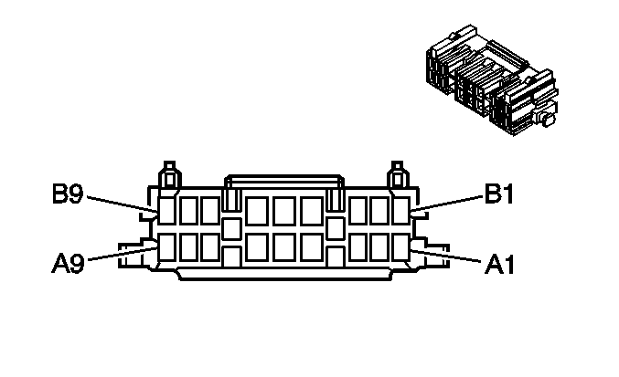
|
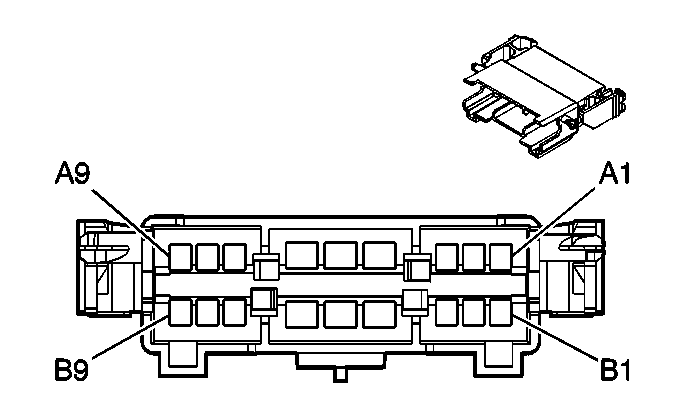
|
Connector Part Information
| Connector Part Information
|
Terminal Part Information
| Terminal Part Information
|
Pin | Wire Color | Circuit No. | Function | Pin | Wire Color | Circuit No. | Function |
|---|---|---|---|---|---|---|---|
A1 | L-GN | 1177 | Door Open Switch Signal | A1 | L-GN | 1177 | Door Open Switch Signal |
A2 | -- | -- | Not Used | A2 | -- | -- | Not Used |
A3 | TN | 294 | Door Lock Actuator Unlock Control (AU3) | A3 | TN | 294 | Door Lock Actuator Unlock Control (AU3) |
A4 | WH | 193 | Rear Defog Relay Supply Voltage (DE5/DE7) | A4 | WH | 193 | Rear Defog Relay Supply Voltage (DE5/DE7) |
A5 | BN/WH | 230 | Instrument Panel Lamps Dimming Control (AU3) | A5 | BN/WH | 230 | Instrument Panel Lamps Dimming Control (AU3/A31) |
BN/WH | 230 | Instrument Panel Lamps Dimming Control (A31) | |||||
A6 | BN/WH | 1498 | Passenger Mirror Motor Down/Right Control (DE5/DE7) | A6 | BN/WH | 1498 | Passenger Mirror Motor Down/Right Control (DE5/DE7) |
BN/WH | 1498 | Passenger Mirror Motor Down/Right Control (DE5/DE7) | |||||
A7 | PU/WH | 889 | Passenger Mirror Motor Up Control (DE5/DE7) | A7 | PU/WH | 889 | Passenger Mirror Motor Up Control (DE5/DE7) |
A8 | GY | 295 | Door Lock Actuator Lock Control (AU3) | A8 | GY | 295 | Door Lock Actuator Lock Control (AU3) |
A9 | WH | 194 | Door Unlock Control (AU3) | A9 | WH | 194 | Door Unlock Control (AU3) |
B1 | L-BU | 195 | Door Lock Control (AU3) | B1 | L-BU | 195 | Door Lock Control (AU3) |
B2 | D-GN/WH | 1335 | Right Mirror Turn Signal Lamp Supply Voltage (DE7) | B2 | D-GN/WH | 1335 | Right Mirror Turn Signal Lamp Supply Voltage (DE7) |
B3 | BK | 450 | Ground | B3 | BK | 450 | Ground |
B4 | D-GN | 1001 | RAP Fuse Supply Voltage (A31) | B4 | D-GN | 1001 | RAP Fuse Supply Voltage (A31) |
B5 | WH | 1185 | Power Window Switch Left Rear Up Signal (A31) | B5 | WH | 1185 | Power Window Switch Left Rear Up Signal (A31) |
B6 | OG | 1189 | Power Window Switch Right Front Low Reference (A31) | B6 | OG | 1189 | Power Window Switch Right Front Low Reference (A31) |
B7 | D-GN | 1953 | Right Front Midrange Speaker Output (-) | B7 | D-GN | 1953 | Right Front Midrange Speaker Output (-) |
B8 | OG | 1853 | Right Front Midrange Speaker Output (+) | B8 | OG | 1853 | Right Front Midrange Speaker Output (+) |
B9 | OG/WH | 881 | Passenger Mirror Motor Left Control (DE5/DE7) | B9 | OG/WH | 881 | Passenger Mirror Motor Left Control (DE5/DE7) |
C314 Chassis Harness to Coolant Heater Jumper Harness (Diesel w/o K08)

|

|
Connector Part Information
| Connector Part Information
|
Terminal Part Information
| Terminal Part Information
|
Pin | Wire Color | Circuit No. | Function | Pin | Wire Color | Circuit No. | Function |
|---|---|---|---|---|---|---|---|
A | RD/WH | 440 | Battery Positive Voltage | A | -- | -- | Not Used |
B | TN | 2501 | High Speed GMLAN Serial Data (-) | B | TN/BK | 2501 | High Speed GMLAN Serial Data (-) (Early Production) |
TN | 2501 | High Speed GMLAN Serial Data (-) (Late Production) | |||||
C | TN/BK | 2500 | High Speed GMLAN Serial Data (+) | C | TN | 2500 | High Speed GMLAN Serial Data (+) (Early Production) |
TN/BK | 2500 | High Speed GMLAN Serial Data (+) (Late Production) | |||||
D | TN | 2501 | High Speed GMLAN Serial Data (-) | D | TN/BK | 2501 | High Speed GMLAN Serial Data (-) (Early Production) |
TN | 2501 | High Speed GMLAN Serial Data (-) (Late Production) | |||||
E | TN/BK | 2500 | High Speed GMLAN Serial Data (+) | E | TN | 2500 | High Speed GMLAN Serial Data (+) (Early Production) |
TN/BK | 2500 | High Speed GMLAN Serial Data (+) (Late Production) | |||||
F | D-BU/GN | 7077 | Coolant Heater - Fuel Pump Control | F | -- | -- | Not Used |
G | -- | -- | Not Used | G | -- | -- | Not Used |
H | BK | 150 | Ground | H | -- | -- | Not Used |
J-K | -- | -- | Not Used | J-K | -- | -- | Not Used |
C316 Transmission Harness to Fuel Pump Harness (Diesel)
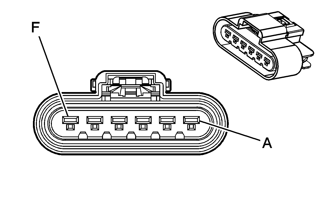
|
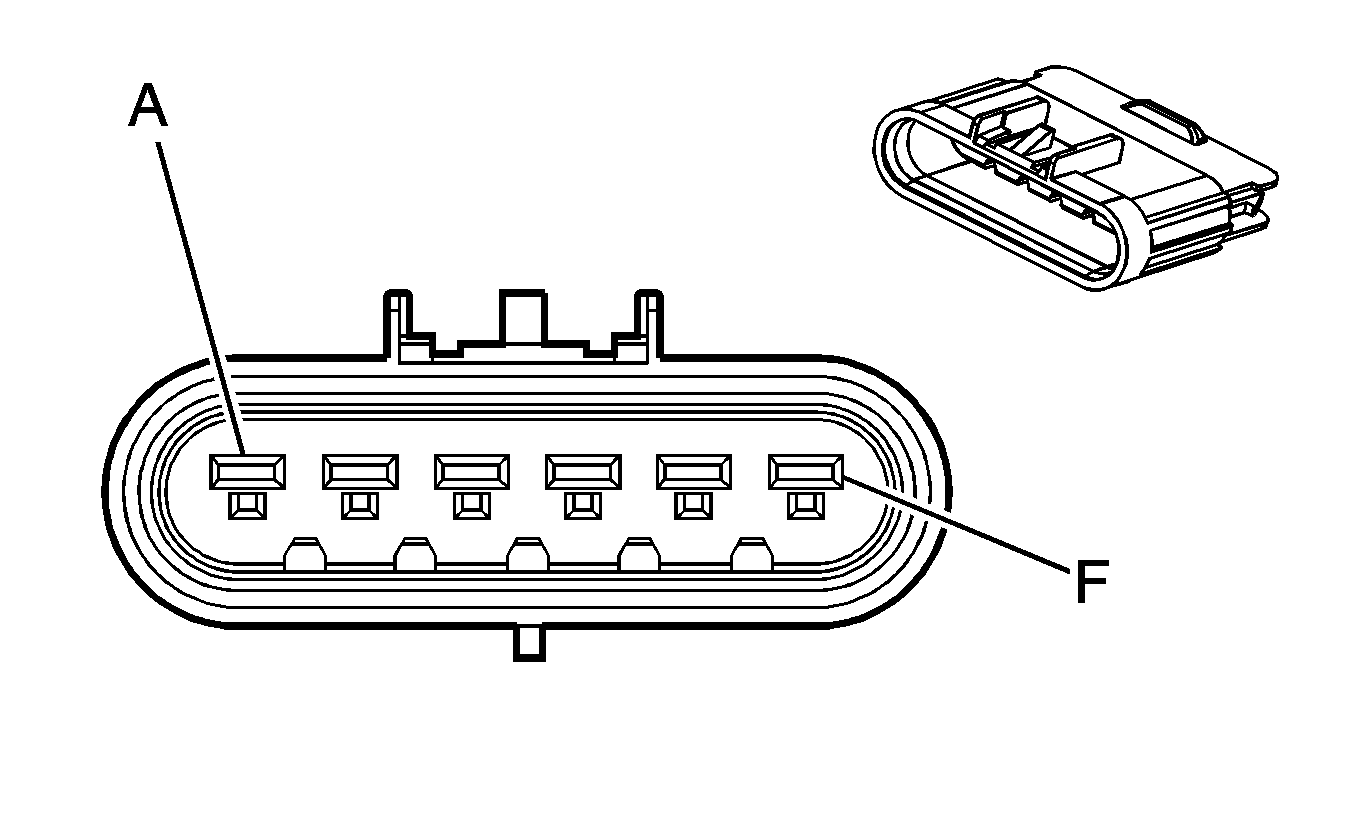
|
Connector Part Information
| Connector Part Information
|
Terminal Part Information
| Terminal Part Information
|
Pin | Wire Color | Circuit No. | Function | Pin | Wire Color | Circuit No. | Function |
|---|---|---|---|---|---|---|---|
A | YE/BK | 508 | Water in Fuel Indicator Control | A | BK | 508 | Water in Fuel Indicator Control |
B | D-BU | 6863 | Low Reference | B | BK | 6863 | Low Reference |
C | BK | 150 | Ground | C | BN | 150 | Ground |
D | PK | 1739 | Ignition 1 Voltage | D | BN | 1739 | Ignition 1 Voltage |
E | BK | 150 | Ground | E | BK | 150 | Ground |
F | L-GN | 1058 | Fuel Pump Supply Voltage | F | RD | 1058 | Fuel Pump Supply Voltage |
C318 I/P Harness to Body Harness
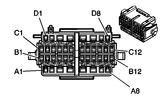
|
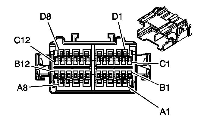
|
Connector Part Information
| Connector Part Information
|
Terminal Part Information
| Terminal Part Information
|
Pin | Wire Color | Circuit No. | Function | Pin | Wire Color | Circuit No. | Function |
|---|---|---|---|---|---|---|---|
A1 | L-BU | 1957 | Left Front Midrange Speaker Output (-) | A1 | L-BU | 1957 | Left Front Midrange Speaker Output (-) |
A2 | D-BU | 1857 | Left Front Midrange Speaker Output (+) | A2 | D-BU | 1857 | Left Front Midrange Speaker Output (+) |
A3 | D-GN | 1953 | Right Front Midrange Speaker Output (-) | A3 | D-GN | 1953 | Right Front Midrange Speaker Output (-) |
A4 | OG | 1853 | Right Front Midrange Speaker Output (+) | A4 | OG | 1853 | Right Front Midrange Speaker Output (+) |
A5 | WH | 1959 | Left Rear Midrange Speaker Output (-) (Passenger/Cargo) | A5 | WH | 1959 | Left Rear Midrange Speaker Output (-) (Passenger/Cargo) |
A6 | TN | 1859 | Left Rear Midrange Speaker Output (+) (Passenger/Cargo) | A6 | TN | 1859 | Left Rear Midrange Speaker Output (+) (Passenger/Cargo) |
A7 | OG | 1955 | Right Rear Midrange Speaker Output (-) (Passenger/Cargo) | A7 | OG | 1955 | Right Rear Midrange Speaker Output (-) (Passenger/Cargo) |
A8 | TN | 1855 | Right Rear Midrange Speaker Output (+) (Passenger/Cargo) | A8 | TN | 1855 | Right Rear Midrange Speaker Output (+) (Passenger/Cargo) |
B1 | -- | -- | Not Used | B1 | -- | -- | Not Used |
B2 | PK | 5017 | Low Reference (Light Duty) | B2 | PK | 5017 | Low Reference (Light Duty) |
B3 | L-GN | 5055 | Seat Position Sensor - Left - Signal (Light Duty) | B3 | L-GN | 5055 | Seat Position Sensor - Left - Signal (Light Duty) |
B4 | TN/WH | 238 | Driver Seat Belt Switch Signal | B4 | TN/WH | 238 | Driver Seat Belt Switch Signal |
B5 | PK | 1139 | Ignition 1 Voltage (Light Duty w/o YF7) | B5 | PK | 1139 | Ignition 1 Voltage (Light Duty w/o YF7) |
B6 | D-BU | 2307 | Passenger Air Bag On Indicator Control (Light Duty w/o YF7) | B6 | D-BU | 2307 | Passenger Air Bag On Indicator Control (Light Duty w/o YF7) |
B7 | D-GN | 2308 | Passenger Air Bag Off Indicator Control (Light Duty w/o YF7) | B7 | D-GN | 2308 | Passenger Air Bag Off Indicator Control (Light Duty w/o YF7) |
B8 | BK/WH | 351 | Ground (Light Duty w/o YF7) | B8 | BK/WH | 351 | Ground (Light Duty w/o YF7) |
B9 | PK | 5018 | Occupant Sensor - Serial Data (Light Duty w/o YF7) | B9 | PK | 5018 | Occupant Sensor - Serial Data (Light Duty w/o YF7) |
B10 | TN/WH | 1362 | Passenger Seat Belt Switch Signal (Light Duty) | B10 | TN/WH | 1362 | Passenger Seat Belt Switch Signal (Light Duty) |
B11 | PU | 493 | Rear Seat Audio Enable Signal (UK6) | B11 | PU | 493 | Rear Seat Audio Enable Signal (UK6) |
B12 | L-GN | 1011 | Remote Radio Control Signal (UK6) | B12 | L-GN | 1011 | Remote Radio Control Signal (UK6) |
C1 | PU | 1375 | Remote Radio Control Supply Voltage (UK6) | C1 | PU | 1375 | Remote Radio Control Supply Voltage (UK6) |
C2 | BK/WH | 351 | Ground (UK6) | C2 | BK/WH | 351 | Ground (UK6) |
C3 | -- | -- | Not Used | C3 | -- | -- | Not Used |
C4 | D-GN | 2087 | Yaw Rate Sensor 5-Volt Reference (JL4) | C4 | D-GN | 2087 | Yaw Rate Sensor 5-Volt Reference (JL4) |
C5 | L-BU | 715 | Lateral Accelerometer Signal (JL4) | C5 | L-BU | 715 | Lateral Accelerometer Signal (JL4) |
C6 | D-BU | 716 | Yaw Rate Sensor Signal (JL4) | C6 | D-BU | 716 | Yaw Rate Sensor Signal (JL4) |
C7 | L-GN/BK | 5352 | Sensor Self Test Signal Circuit (JL4) | C7 | L-GN/BK | 5352 | Sensor Self Test Signal Circuit (JL4) |
C8 | YE | 5353 | Yaw Rate Frequency (JL4) | C8 | YE | 5353 | Yaw Rate Frequency (JL4) |
C9 | L-BU | 2088 | Yaw Rate Sensor Low Reference (JL4) | C9 | L-BU | 2088 | Yaw Rate Sensor Low Reference (JL4) |
C10 | -- | -- | Not Used | C10 | -- | -- | Not Used |
C11 | L-BU | 5056 | Seat Position Sensor - Right - Signal (Light Duty) | C11 | L-BU | 5056 | Seat Position Sensor - Right - Signal (Light Duty) |
C12 | -- | -- | Not Used | C12 | -- | -- | Not Used |
D1 | -- | -- | Not Used | D1 | -- | -- | Not Used |
D2 | TN | 126 | Left Front Door Open Switch Signal | D2 | TN | 126 | Left Front Door Open Switch Signal |
D3 | L-GN | 24 | Backup Lamp Supply Voltage (Passenger/Cargo) | D3 | L-GN | 24 | Backup Lamp Supply Voltage (Passenger/Cargo) |
L-GN | 24 | Backup Lamp Supply Voltage (Cargo/Passenger w/DF5) | |||||
D4 | YE/BK | 1181 | Rear Door Open Switch Signal (Passenger/Cargo) | D4 | YE/BK | 1181 | Rear Door Open Switch Signal (Passenger/Cargo) |
YE/BK | 1181 | Rear Door Open Switch Signal (E26) | |||||
D5 | OG | 1732 | Inadvertent Power Supply Voltage | D5 | OG | 1732 | Inadvertent Power Supply Voltage |
OG | 1732 | Inadvertent Power Supply Voltage | |||||
D6 | L-GN | 1177 | Door Open Switch Signal | D6 | L-GN | 1177 | Door Open Switch Signal |
L-GN | 1177 | Door Open Switch Signal (Passenger/Cargo) | |||||
D7-D8 | -- | -- | Not Used | D7-D8 | -- | -- | Not Used |
C319 Rear Heater Switch Harness to Body Harness (C36 w/o C69)

|

|
Connector Part Information
| Connector Part Information
|
Terminal Part Information
| Terminal Part Information
|
Pin | Wire Color | Circuit No. | Function | Pin | Wire Color | Circuit No. | Function |
|---|---|---|---|---|---|---|---|
A | WH | 1924 | Auxiliary Blower Motor High Control | A | WH | 1924 | Auxiliary Blower Motor High Control |
B | OG | 1925 | Auxiliary Blower Motor Medium Control | B | OG | 1925 | Auxiliary Blower Motor Medium Control |
C | D-BU | 1926 | Auxiliary Blower Motor Low Control | C | D-BU | 1926 | Auxiliary Blower Motor Low Control |
D | BN/WH | 230 | Instrument Panel Lamps Dimming Control | D | BN/WH | 230 | Instrument Panel Lamps Dimming Control |
E | BK | 450 | Ground | E | BK | 450 | Ground |
F-H | -- | -- | Not Used | F-H | -- | -- | Not Used |
C319 Upfitter Harness to Body Harness (C69/ENC)
-- |

|
Connector Part Information
| Connector Part Information
|
Terminal Part Information
| Terminal Part Information
|
Pin | Wire Color | Circuit No. | Function | Pin | Wire Color | Circuit No. | Function |
|---|---|---|---|---|---|---|---|
A | -- | -- | Upfitter Usage | A | WH | 1924 | Auxiliary Blower Motor High Control |
B | -- | -- | Upfitter Usage | B | OG | 1925 | Auxiliary Blower Motor Medium Control |
C | -- | -- | Upfitter Usage | C | D-BU | 1926 | Auxiliary Blower Motor Low Control |
D | -- | -- | Upfitter Usage | D | BN/WH | 230 | Instrument Panel Lamps Dimming Control |
E | -- | -- | Upfitter Usage | E | BK | 450 | Ground |
F-H | -- | -- | Upfitter Usage | F-H | -- | -- | Not Used |
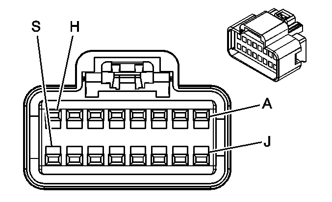
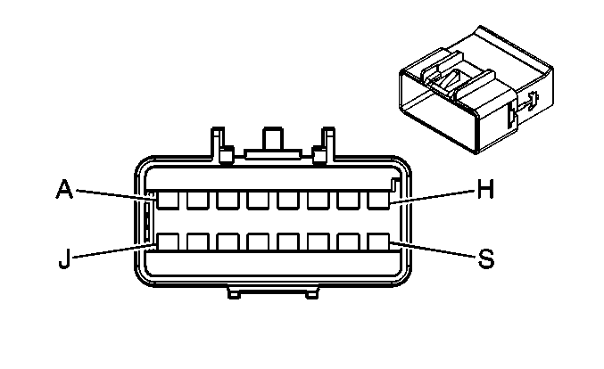
C320 Upfitter Harness to Body Harness (YF7)
|
|
Connector Part Information
| Connector Part Information
|
Terminal Part Information
| Terminal Part Information
|
Pin | Wire Color | Circuit No. | Function | Pin | Wire Color | Circuit No. | Function |
|---|---|---|---|---|---|---|---|
A | WH | 1959 | Left Rear Midrange Speaker Output (-) (UK6) | A | WH | 1959 | Left Rear Midrange Speaker Output (-) |
B | TN | 1859 | Left Rear Midrange Speaker Output (+) (UK6) | B | TN | 1859 | Left Rear Midrange Speaker Output (+) |
C | OG | 1955 | Right Rear Midrange Speaker Output (-) (UK6) | C | OG | 1955 | Right Rear Midrange Speaker Output (-) |
D | TN | 1855 | Right Rear Midrange Speaker Output (+) (UK6) | D | TN | 1855 | Right Rear Midrange Speaker Output (+) |
E | PU | 493 | Rear Seat Audio Enable Signal (UK6) | E | PU | 493 | Rear Seat Audio Enable Signal (UK6) |
F | L-GN | 1011 | Remote Radio Control Signal (UK6) | F | L-GN | 1011 | Remote Radio Control Signal (UK6) |
G | PU | 1375 | Remote Radio Control Supply Voltage (UK6) | G | PU | 1375 | Remote Radio Control Supply Voltage (UK6) |
H | BN/WH | 230 | Instrument Panel Lamps Dimming Control (UK6) | H | BN/WH | 230 | Instrument Panel Lamps Dimming Control (UK6) |
J | BK/WH | 351 | Ground (UK6) | J | BK/WH | 351 | Ground (UK6) |
K | WH | 1959 | Left Rear Midrange Speaker Output (-) (UK6) | K | WH | 1959 | Left Rear Midrange Speaker Output (-) (UK6) |
L | TN | 1859 | Left Rear Midrange Speaker Output (+) (UK6) | L | TN | 1859 | Left Rear Midrange Speaker Output (+) (UK6) |
M | OG | 1955 | Right Rear Midrange Speaker Output (-) (UK6) | M | OG | 1955 | Right Rear Midrange Speaker Output (-) (UK6) |
N | TN | 1855 | Right Rear Midrange Speaker Output (+) (UK6) | N | TN | 1855 | Right Rear Midrange Speaker Output (+) (UK6) |
P | -- | -- | Upfitter Usage | P | BK | 450 | Ground |
R | -- | -- | Upfitter Usage | R | D-BU/WH | 149 | Courtesy Lamp Supply Voltage |
S | -- | -- | Upfitter Usage | S | BN | 2209 | Rear Park Lamps Supply Voltage |
C321 Upfitter Harness to Body Harness (YF7)
-- |

|
Connector Part Information
| Connector Part Information
|
Terminal Part Information
| Terminal Part Information
|
Pin | Wire Color | Circuit No. | Function | Pin | Wire Color | Circuit No. | Function |
|---|---|---|---|---|---|---|---|
A | -- | -- | Upfitter Usage | A | RD/BK | 1042 | Battery Positive Voltage |
B | -- | -- | Upfitter Usage | B | BN | 541 | Ignition 3 Voltage |
C | -- | -- | Upfitter Usage | C | BK | 450 | Ground |
D | -- | -- | Upfitter Usage | D | -- | -- | Not Used |
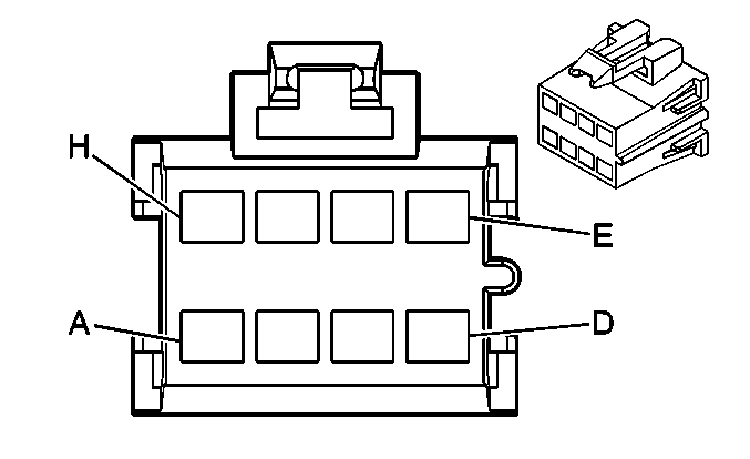
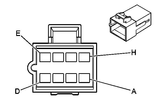
C400 RR Cargo Door Harness to Body Harness (Passenger/Cargo)
|
|
Connector Part Information
| Connector Part Information
|
Terminal Part Information
| Terminal Part Information
|
Pin | Wire Color | Circuit No. | Function | Pin | Wire Color | Circuit No. | Function |
|---|---|---|---|---|---|---|---|
A | TN | 1855 | Right Rear Midrange Speaker Output (+) | A | TN | 1855 | Right Rear Midrange Speaker Output (+) |
B | OG | 1955 | Right Rear Midrange Speaker Output (-) | B | OG | 1955 | Right Rear Midrange Speaker Output (-) |
C | -- | -- | Not Used | C | -- | -- | Not Used |
D | WH | 194 | Door Unlock Control (AU3) | D | WH | 194 | Door Unlock Control (AU3) |
E | L-BU | 195 | Door Lock Control (AU3) | E | L-BU | 195 | Door Lock Control (AU3) |
F | L-GN | 1177 | Door Open Switch Signal | F | L-GN | 1177 | Door Open Switch Signal |
G | TN/BK | 1095 | Right Rear Door Lock Actuator Unlock Control (AU3) | G | TN/BK | 1095 | Right Rear Door Lock Actuator Unlock Control (AU3) |
H | GY | 295 | Door Lock Actuator Lock Control (AU3) | H | GY | 295 | Door Lock Actuator Lock Control (AU3) |
C401 Left Tail Lamp Harness to Body Harness (Passenger/Cargo)

|

|
Connector Part Information
| Connector Part Information
|
Terminal Part Information
| Terminal Part Information
|
Pin | Wire Color | Circuit No. | Function | Pin | Wire Color | Circuit No. | Function |
|---|---|---|---|---|---|---|---|
A | BN | 2509 | Left Rear Park Lamps Supply Voltage | A | BN | 2509 | Left Rear Park Lamps Supply Voltage |
BN | 2509 | Left Rear Park Lamps Supply Voltage | |||||
B | YE | 618 | Left Rear Turn Signal Lamp Supply Voltage | B | YE | 618 | Left Rear Turn Signal Lamp Supply Voltage |
C | -- | -- | Not Used | C | -- | -- | Not Used |
D | BK | 850 | Ground | D | BK | 850 | Ground |
E | -- | -- | Not Used | E | -- | -- | Not Used |
F | L-GN | 24 | Backup Lamp Supply Voltage | F | L-GN | 24 | Backup Lamp Supply Voltage |
C402 Right Tail Lamp Harness to Body Harness (Passenger/Cargo)

|

|
Connector Part Information
| Connector Part Information
|
Terminal Part Information
| Terminal Part Information
|
Pin | Wire Color | Circuit No. | Function | Pin | Wire Color | Circuit No. | Function |
|---|---|---|---|---|---|---|---|
A | BN | 2609 | Right Rear Park Lamps Supply Voltage | A | BN | 2609 | Right Rear Park Lamps Supply Voltage |
B | YE | 619 | Right Rear Turn Signal Lamp Supply Voltage | B | D-GN | 619 | Right Rear Turn Signal Lamp Supply Voltage |
C | -- | -- | Not Used | C | -- | -- | Not Used |
D | BK | 1050 | Ground | D | BK | 1050 | Ground |
E | -- | -- | Not Used | E | -- | -- | Not Used |
F | L-GN | 24 | Backup Lamp Supply Voltage | F | L-GN | 24 | Backup Lamp Supply Voltage |
C405 Chassis Harness to Rear Lighting Cap (Cutaway)

|

|
Connector Part Information
| Connector Part Information
|
Terminal Part Information
| Terminal Part Information
|
Pin | Wire Color | Circuit No. | Function | Pin | Wire Color | Circuit No. | Function |
|---|---|---|---|---|---|---|---|
A | -- | -- | Upfitter Usage | A | YE/BK | 1334 | Left Rear Turn Signal Lamp Supply Voltage |
B | -- | -- | Upfitter Usage | B | D-GN/WH | 1335 | Right Rear Turn Signal Lamp Supply Voltage |
C | L-BU | 1320 | Stop Lamp Supply Voltage - w/Cap Installed | C | WH | 17 | Stop Lamp Switch Signal |
-- | -- | Upfitter Usage - w/o Cap | |||||
D | -- | -- | Upfitter Usage | D | YE | 618 | Left Rear Turn Signal Lamp Supply Voltage |
E | -- | -- | Upfitter Usage | E | D-GN | 619 | Right Rear Turn Signal Lamp Supply Voltage |
F | -- | -- | Upfitter Usage | F | BN | 2109 | Trailer Park Lamps Supply Voltage |
G | BK | 150 | Ground - w/Cap Installed | G | BK | 150 | Ground |
-- | -- | Upfitter Usage - w/o Cap | |||||
H | -- | -- | Upfitter Usage | H | L-GN | 1624 | Trailer Backup Lamps Supply Voltage |
J | -- | -- | Not Used | J | -- | -- | Not Used |
K | -- | -- | Upfitter Usage | K | D-BU/WH | 149 | Courtesy Lamp Supply Voltage |
C406 Rear Fog Lamp Harness to Chassis Harness (T79)

|

|
Connector Part Information
| Connector Part Information
|
Terminal Part Information
| Terminal Part Information
|
Pin | Wire Color | Circuit No. | Function | Pin | Wire Color | Circuit No. | Function |
|---|---|---|---|---|---|---|---|
A | OG | 122 | Rear Fog Lamp Supply Voltage | A | OG | 122 | Rear Fog Lamp Supply Voltage |
B | BK | 150 | Ground | B | BK | 150 | Ground |
C407 Rear HVAC Harness to Body Harness (C36/C69)

|

|
Connector Part Information
| Connector Part Information
|
Terminal Part Information
| Terminal Part Information
|
Pin | Wire Color | Circuit No. | Function | Pin | Wire Color | Circuit No. | Function |
|---|---|---|---|---|---|---|---|
A | GY | 2599 | Auxiliary Mode Door Control (C69) | A | GY | 2599 | Auxiliary Mode Door Control (C69) |
B | D-BU | 1926 | Auxiliary Blower Motor Low Control | B | D-BU | 1926 | Auxiliary Blower Motor Low Control |
C | WH | 1924 | Auxiliary Blower Motor High Control | C | WH | 1924 | Auxiliary Blower Motor High Control |
D | OG | 1925 | Auxiliary Blower Motor Medium Control | D | OG | 1925 | Auxiliary Blower Motor Medium Control |
E | BN | 341 | Ignition 3 Voltage | E | BN | 341 | Ignition 3 Voltage |
F | OG | 2775 | Auxiliary Air Temperature Door Control (C69) | F | OG | 2775 | Auxiliary Air Temperature Door Control (C69) |
C407 Upfitter Harness to Body Harness (ENC)
-- |

|
Connector Part Information
| Connector Part Information
|
Terminal Part Information
| Terminal Part Information
|
Pin | Wire Color | Circuit No. | Function | Pin | Wire Color | Circuit No. | Function |
|---|---|---|---|---|---|---|---|
A | -- | -- | Upfitter Usage | A | -- | -- | Not Used |
B | -- | -- | Upfitter Usage | B | D-BU | 1926 | Auxiliary Blower Motor Low Control |
C | -- | -- | Upfitter Usage | C | WH | 1924 | Auxiliary Blower Motor High Control |
D | -- | -- | Upfitter Usage | D | OG | 1925 | Auxiliary Blower Motor Medium Control |
E | -- | -- | Upfitter Usage | E | BN | 341 | Ignition 3 Voltage |
F | -- | -- | Upfitter Usage | F | -- | -- | Not Used |
C409 Rear HVAC Harness to Body Harness (C36/C69)
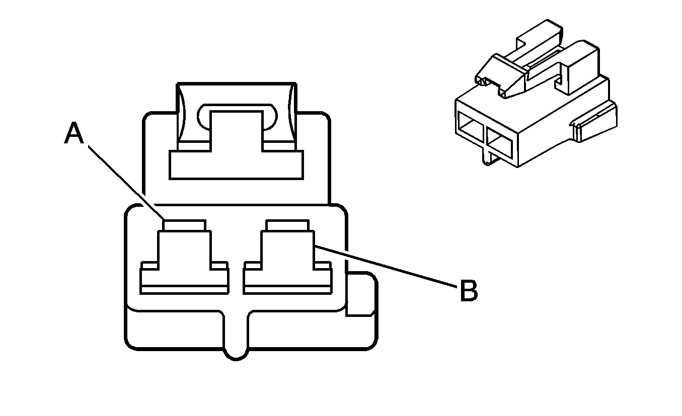
|
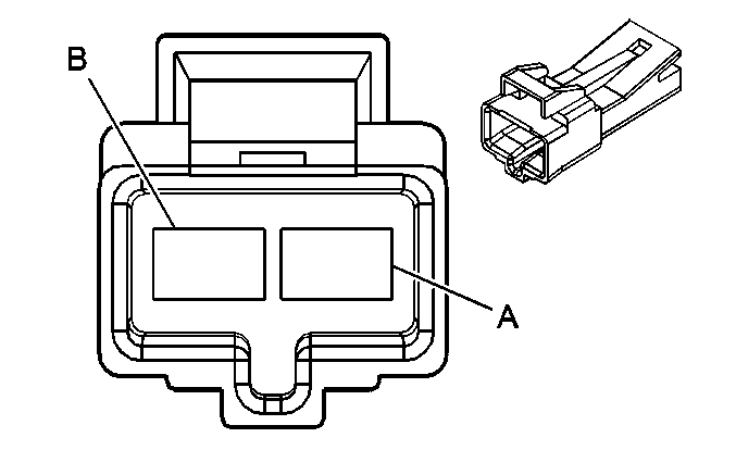
|
Connector Part Information
| Connector Part Information
|
Terminal Part Information
| Terminal Part Information
|
Pin | Wire Color | Circuit No. | Function | Pin | Wire Color | Circuit No. | Function |
|---|---|---|---|---|---|---|---|
A | RD/WH | 1740 | Battery Positive Voltage | A | RD/WH | 1740 | Battery Positive Voltage |
B | BK | 850 | Ground | B | BK | 850 | Ground |
C409 Upfitter Harness to Body Harness (ENC)
-- |

|
Connector Part Information
| Connector Part Information
|
Terminal Part Information
| Terminal Part Information
|
Pin | Wire Color | Circuit No. | Function | Pin | Wire Color | Circuit No. | Function |
|---|---|---|---|---|---|---|---|
A | -- | -- | Upfitter Usage | A | RD/WH | 1740 | Battery Positive Voltage |
B | -- | -- | Upfitter Usage | B | BK | 450 | Ground |
C411 Left Cargo Door Harness to Body Harness (Passenger/Cargo)

|

|
Connector Part Information
| Connector Part Information
|
Terminal Part Information
| Terminal Part Information
|
Pin | Wire Color | Circuit No. | Function | Pin | Wire Color | Circuit No. | Function |
|---|---|---|---|---|---|---|---|
A | TN | 1859 | Left Rear Midrange Speaker Output (+) (UB1/UC6) | A | TN | 1859 | Left Rear Midrange Speaker Output (+) |
B | WH | 1959 | Left Rear Midrange Speaker Output (-) (UB1/UC6) | B | WH | 1959 | Left Rear Midrange Speaker Output (-) |
C | -- | -- | Not Used | C | -- | -- | Not Used |
D | PU | 293 | Rear Defog Element Supply Voltage (C49) | D | PU | 293 | Rear Defog Element Supply Voltage (C49) |
E | BK | 850 | Ground (C49) | E | BK | 850 | Ground (C49) |
F | -- | -- | Not Used | F | -- | -- | Not Used |
C412 Right Cargo Door Harness to Body Harness (Passenger/Cargo)
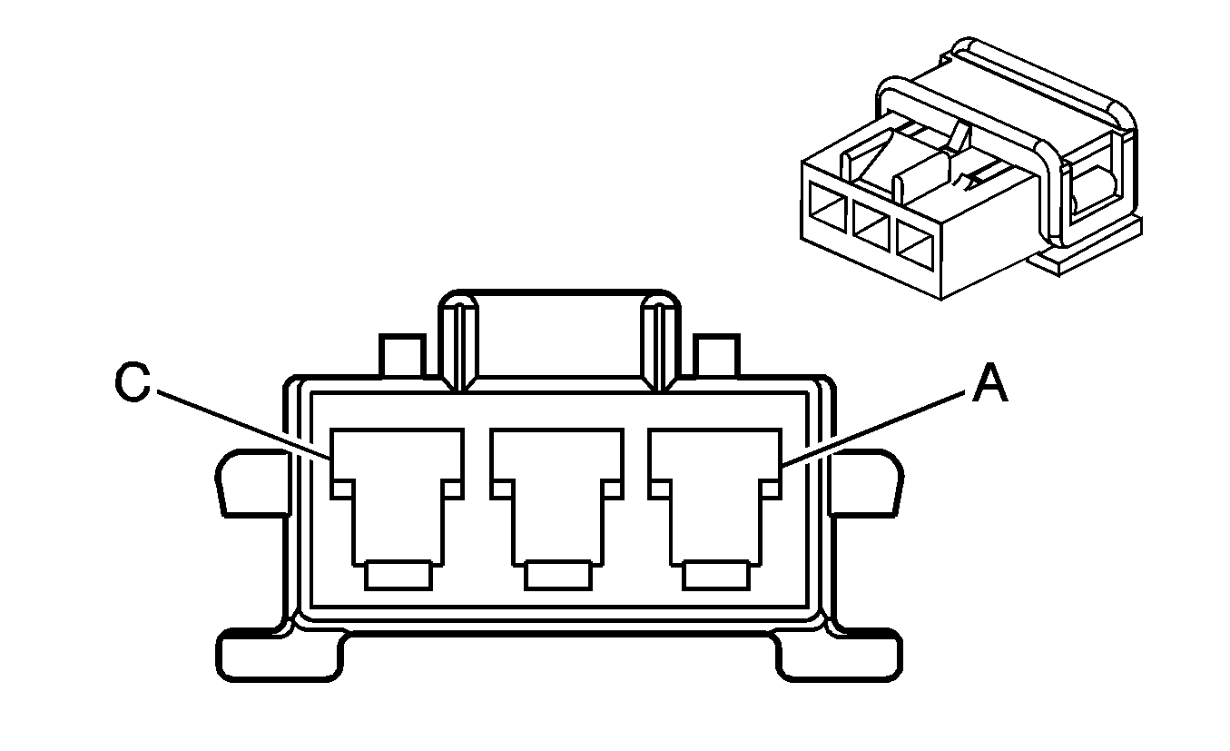
|
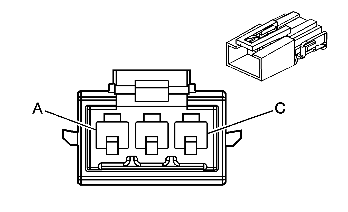
|
Connector Part Information
| Connector Part Information
|
Terminal Part Information
| Terminal Part Information
|
Pin | Wire Color | Circuit No. | Function | Pin | Wire Color | Circuit No. | Function |
|---|---|---|---|---|---|---|---|
A | PU | 293 | Rear Defog Element Supply Voltage (C49) | A | PU | 293 | Rear Defog Element Supply Voltage (C49) |
B | BK | 1050 | Ground | B | BK | 1050 | Ground |
C | BN | 2509 | Left Rear Park Lamps Supply Voltage | C | BN | 2509 | Left Rear Park Lamps Supply Voltage |
C413 Chassis Harness to LR Wheel Speed Sensor Harness (JL4)

|

|
Connector Part Information
| Connector Part Information
|
Terminal Part Information
| Terminal Part Information
|
Pin | Wire Color | Circuit No. | Function | Pin | Wire Color | Circuit No. | Function |
|---|---|---|---|---|---|---|---|
A | BK | 884 | Left Rear Wheel Speed Sensor Signal | A | BK | 884 | Left Rear Wheel Speed Sensor Signal |
B | RD | 885 | Left Rear Wheel Speed Sensor Low Reference | B | RD | 885 | Left Rear Wheel Speed Sensor Low Reference |
C414 Chassis Harness to RR Wheel Speed Sensor Harness (JL4)

|

|
Connector Part Information
| Connector Part Information
|
Terminal Part Information
| Terminal Part Information
|
Pin | Wire Color | Circuit No. | Function | Pin | Wire Color | Circuit No. | Function |
|---|---|---|---|---|---|---|---|
A | BN | 882 | Right Rear Wheel Speed Sensor Signal | A | BN | 882 | Right Rear Wheel Speed Sensor Signal |
B | WH | 883 | Right Rear Wheel Speed Sensor Low Reference | B | WH | 883 | Right Rear Wheel Speed Sensor Low Reference |
C415 Rear Overhead Speaker Harness to Body Harness (Passenger/Cargo)
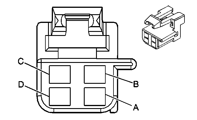
|

|
Connector Part Information
| Connector Part Information
|
Terminal Part Information
| Terminal Part Information
|
Pin | Wire Color | Circuit No. | Function | Pin | Wire Color | Circuit No. | Function |
|---|---|---|---|---|---|---|---|
A | WH | 1959 | Left Rear Midrange Speaker Output (-) (Passenger/Cargo) | A | WH | 1959 | Left Rear Midrange Speaker Output (-) |
B | TN | 1859 | Left Rear Midrange Speaker Output (+) (Passenger/Cargo) | B | TN | 1859 | Left Rear Midrange Speaker Output (+) |
C | OG | 1955 | Right Rear Midrange Speaker Output (-) (Passenger/Cargo) | C | OG | 1955 | Right Rear Midrange Speaker Output (-) |
D | TN | 1855 | Right Rear Midrange Speaker Output (+) (Passenger/Cargo) | D | TN | 1855 | Right Rear Midrange Speaker Output (+) |
C417 Dome Lamp Harness to Body Harness (Cargo w/o YF7)

|

|
Connector Part Information
| Connector Part Information
|
Terminal Part Information
| Terminal Part Information
|
Pin | Wire Color | Circuit No. | Function | Pin | Wire Color | Circuit No. | Function |
|---|---|---|---|---|---|---|---|
A | D-BU/WH | 149 | Courtesy Lamp Supply Voltage | A | D-BU/WH | 149 | Courtesy Lamp Supply Voltage |
B | BK | 850 | Ground | B | BK | 850 | Ground |
C419 CHMSL Harness to Body Harness (Passenger/Cargo)

|

|
Connector Part Information
| Connector Part Information
|
Terminal Part Information
| Terminal Part Information
|
Pin | Wire Color | Circuit No. | Function | Pin | Wire Color | Circuit No. | Function |
|---|---|---|---|---|---|---|---|
A | L-BU | 1320 | CHMSL Supply Voltage | A | L-BU | 1320 | CHMSL Supply Voltage |
B | BK | 850 | Ground | B | BK | 850 | Ground |
C420 Front Headliner Harness to Rear Headliner Harness (Rear Auxiliary Controls w/o YF7)
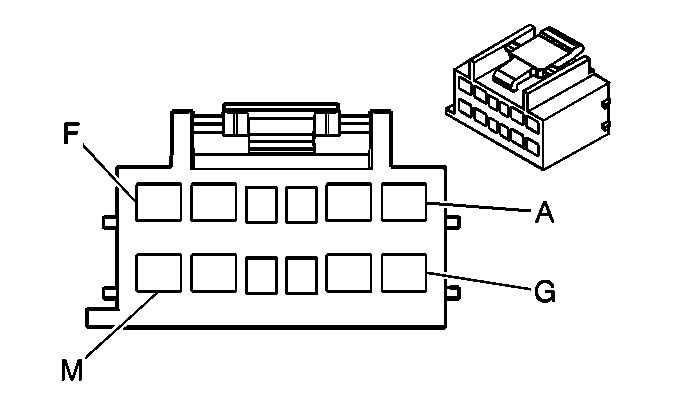
|
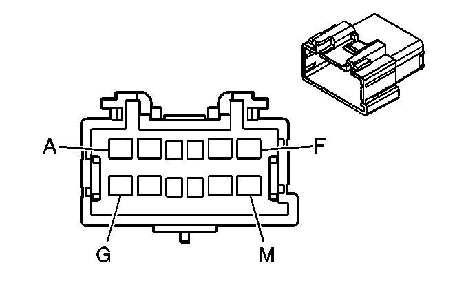
|
Connector Part Information
| Connector Part Information
|
Terminal Part Information
| Terminal Part Information
|
Pin | Wire Color | Circuit No. | Function | Pin | Wire Color | Circuit No. | Function |
|---|---|---|---|---|---|---|---|
A | OG | 1925 | Auxiliary Blower Motor Medium Speed Control | A | OG | 1925 | Auxiliary Blower Motor Medium Speed Control |
B | D-BU | 1926 | Auxiliary Blower Motor Low Speed Control | B | D-BU | 1926 | Auxiliary Blower Motor Low Speed Control |
C | D-BU/WH | 149 | Courtesy Lamp Supply Voltage | C | D-BU/WH | 149 | Courtesy Lamp Supply Voltage |
D | D-BU/WH | 149 | Courtesy Lamp Supply Voltage | D | D-BU/WH | 149 | Courtesy Lamp Supply Voltage |
E | OG | 1732 | Inadvertent Power Supply Voltage | E | OG | 1732 | Inadvertent Power Supply Voltage |
F | BN | 341 | Ignition 3 Voltage | F | BN | 341 | Ignition 3 Voltage |
G | BN/WH | 230 | Instrument Panel Lamps Dimming Control | G | BN/WH | 230 | Instrument Panel Lamps Dimming Control |
H | WH | 1924 | Auxiliary Blower Motor High Speed Control | H | WH | 1924 | Auxiliary Blower Motor High Speed Control |
J | PU/WH | 5264 | Rear Auxiliary Mode Door Control | J | PU/WH | 5264 | Rear Auxiliary Mode Door Control |
K | BN | 5263 | Rear Auxiliary Air Temperature Door Control | K | BN | 5263 | Rear Auxiliary Air Temperature Door Control |
L | PK/BK | 5265 | Rear Auxiliary Blower Motor Switch Control | L | PK/BK | 5265 | Rear Auxiliary Blower Motor Switch Control |
M | BK | 450 | Ground | M | BK | 450 | Ground |
C901 Rear Window Defogger Jumper Harness to Left Cargo Door Harness (C49 w/A12)

|

|
Connector Part Information
| Connector Part Information
|
Terminal Part Information
| Terminal Part Information
|
Pin | Wire Color | Circuit No. | Function | Pin | Wire Color | Circuit No. | Function |
|---|---|---|---|---|---|---|---|
A | BK | 293 | Rear Defog Element Supply Voltage | A | PU | 293 | Rear Defog Element Supply Voltage |
B | BK | 850 | Ground | B | BK | 850 | Ground |
C902 Rear Window Defogger Jumper Harness to Right Cargo Door Harness (C49 w/A12)

|

|
Connector Part Information
| Connector Part Information
|
Terminal Part Information
| Terminal Part Information
|
Pin | Wire Color | Circuit No. | Function | Pin | Wire Color | Circuit No. | Function |
|---|---|---|---|---|---|---|---|
A | BK | 293 | Rear Defog Element Supply Voltage | A | PU | 293 | Rear Defog Element Supply Voltage |
B | BK | 1050 | Ground | B | BK | 1050 | Ground |
