For 1990-2009 cars only
Caution: Refer to Brake Fluid Irritant Caution in the Preface section.
Notice: Refer to Brake Fluid Effects on Paint and Electrical Components Notice in the Preface section.
Removal Procedure
- Apply the park brake and block the wheels.
- Disconnect the electrical connector from the brake fluid level sensor, if applicable.
- Remove the driver side upper fender support.
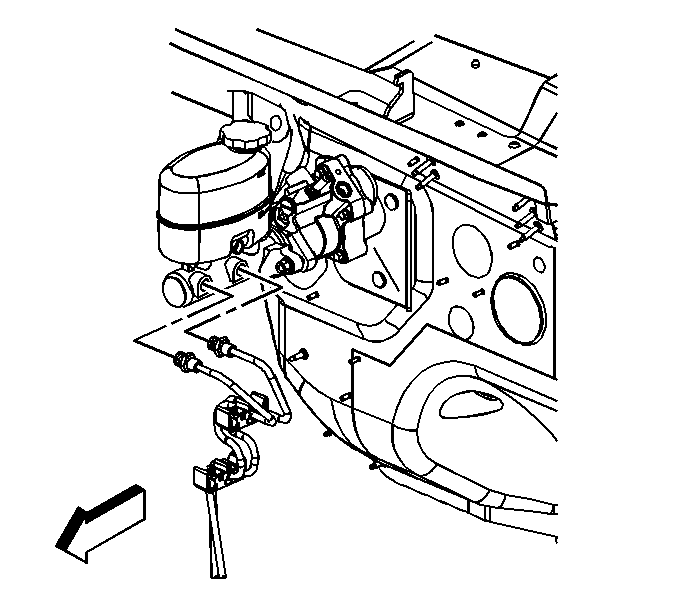
- Disconnect the brake pipes from the master cylinder.
- Plug the open brake pipe ends.
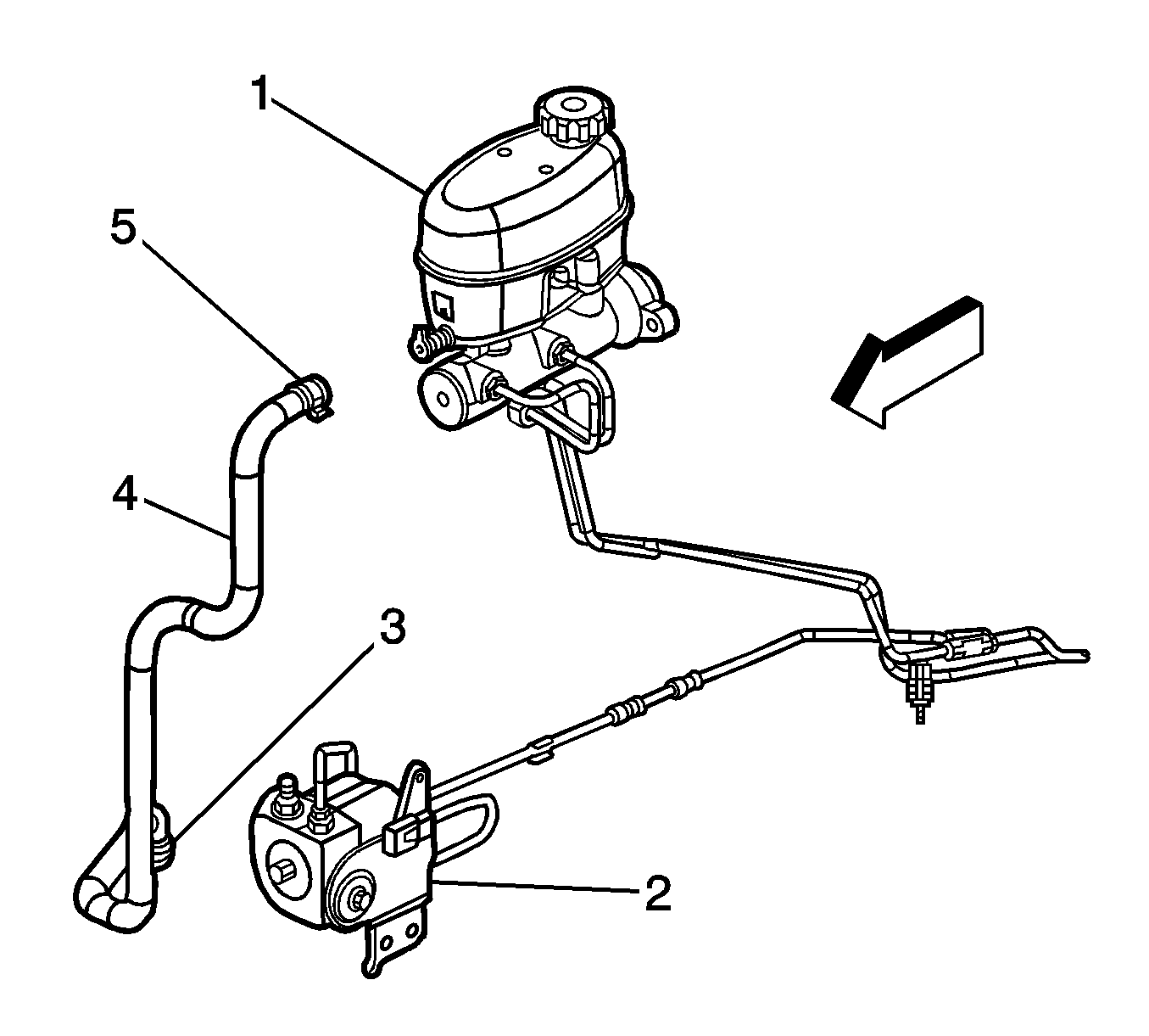
- For vehicles with JL4, crimp the hose (4) at the master cylinder to prevent fluid from leaking out.
- Remove the clamp (5) and hose (4) from the reservoir. Plug the port in the reservoir.
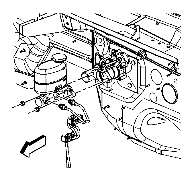
- Remove the master cylinder mounting nuts.
- Remove the master cylinder from the vehicle.
- Remove the master cylinder reservoir. Refer to Master Cylinder Reservoir Replacement .

Important: Install a rubber cap or plug to the exposed brake pipe fitting ends in order to prevent brake fluid loss and contamination.


Installation Procedure
- Install the master cylinder reservoir. Refer to Master Cylinder Reservoir Replacement .
- Bench bleed the master cylinder. Refer to Master Cylinder Bench Bleeding .
- Install the master cylinder to the vehicle.
- Install the master cylinder mounting nuts.
- For vehicles with JL4, remove the plug from the reservoir port and install the hose (4) and clamp (5) to the reservoir.
- Remove the crimping tool from the hose (4).
- Connect the brake pipes.
- Connect the electrical connector to the brake fluid level sensor.
- Install the driver side upper fender support.
- Bleed the hydraulic brake system. Refer to Hydraulic Brake System Bleeding .
- Release the park brake and unblock the wheels.

Notice: Refer to Fastener Notice in the Preface section.
Tighten
Tighten the nuts to 36 N·m (27 lb ft).


Remove the rubber cap or plug from the exposed brake pipe fitting ends.
Tighten
Tighten the pipe fittings to 25 N·m (18 lb ft).
