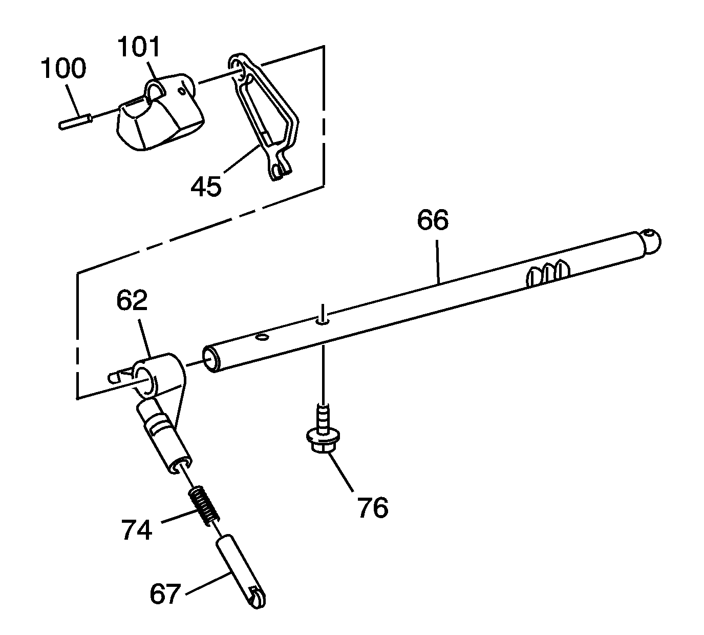
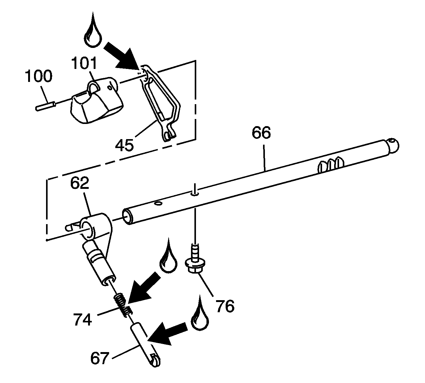
- Using a suitable punch and hammer, remove the pin (100) from the dynamic damper weight (101).
- Remove the shift shaft detent cam (45) and the weight (101) from the shift control shaft (66).
- Remove the shift shaft detent (67) and the shift shaft detent spring (74).
- Remove the bolt (76) from the shift shaft detent lever (62).
- Remove the shift shaft detent lever (62) from the shift control shaft (66).
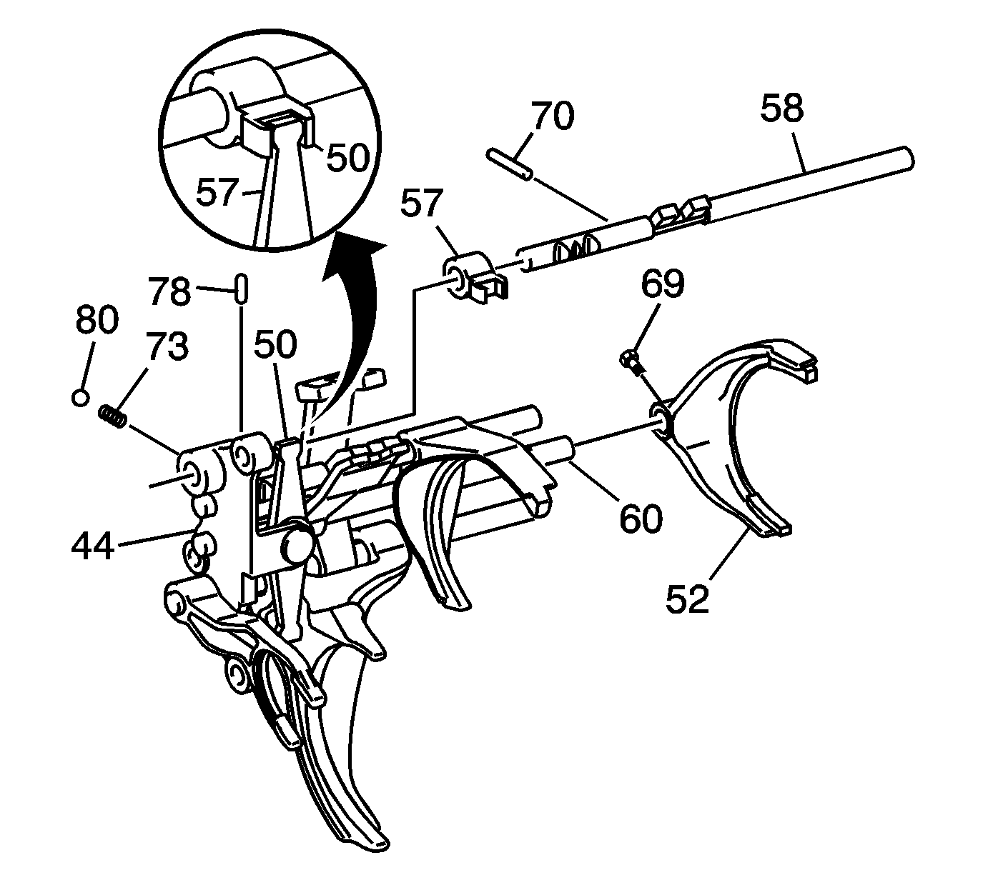
- Remove the 1st/2nd shift fork pin (70).
- Remove the 1st/2nd shift shaft (58).
- Remove the slotted pin (70) from the select control lever assembly (57). Slide the select control lever assembly (57) from the 1st/2nd shift shaft (58).
- Using a suitable punch and hammer, remove the pin (78) from the shift control lever bracket (44).
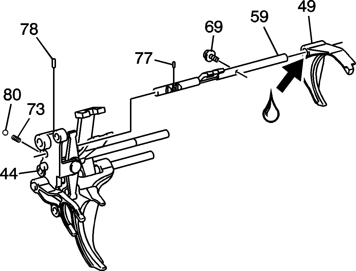
- Remove the bolt (69) from the 3rd/4th shift fork (49).
- Remove the 3rd/4th shift shaft (59).
- Remove the shift fork (49).
- Use a magnet to remove pins (77 and 78).
- Remove the bolt (69) from the 5th/6th shift fork (52). Slide the 5th/6th shift fork (52) from the 5th/6th shift shaft (60).
- Remove the 5th/6th shift shaft (60).
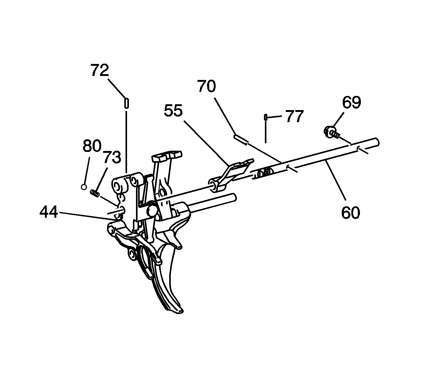
- Using a suitable punch and hammer, remove the pin (70) from the shift lever assembly (55). Slide the shift lever assembly (55) from the 5th/6th shift shaft (60).
- Using a suitable punch and hammer, remove pins (77 and 72).
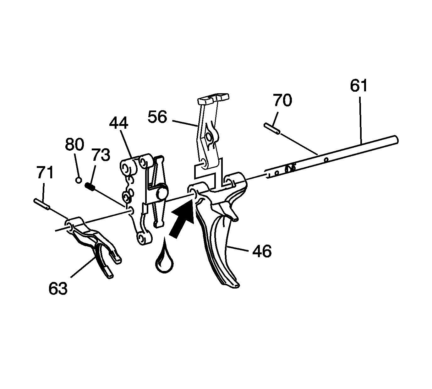
- Using a suitable punch and hammer, remove the slotted pin (71) from the reverse shift fork (63). Slide the reverse shift fork (63) off the reverse shift shaft (61).
- Remove the reverse shift shaft assembly.
- Using a suitable punch and hammer, remove the slotted pin (70) from the intl shift control lever (56). Slide the intl shift control lever (56) and 1st/2nd shift fork assembly (46) from the reverse shift shaft (61).
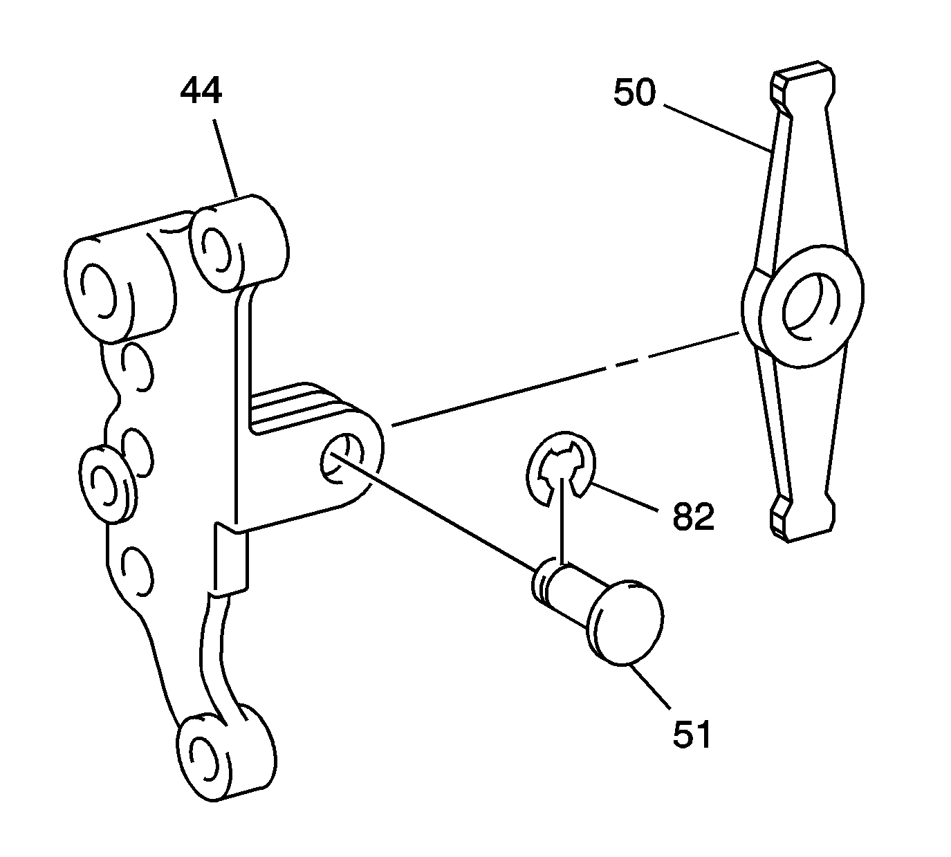
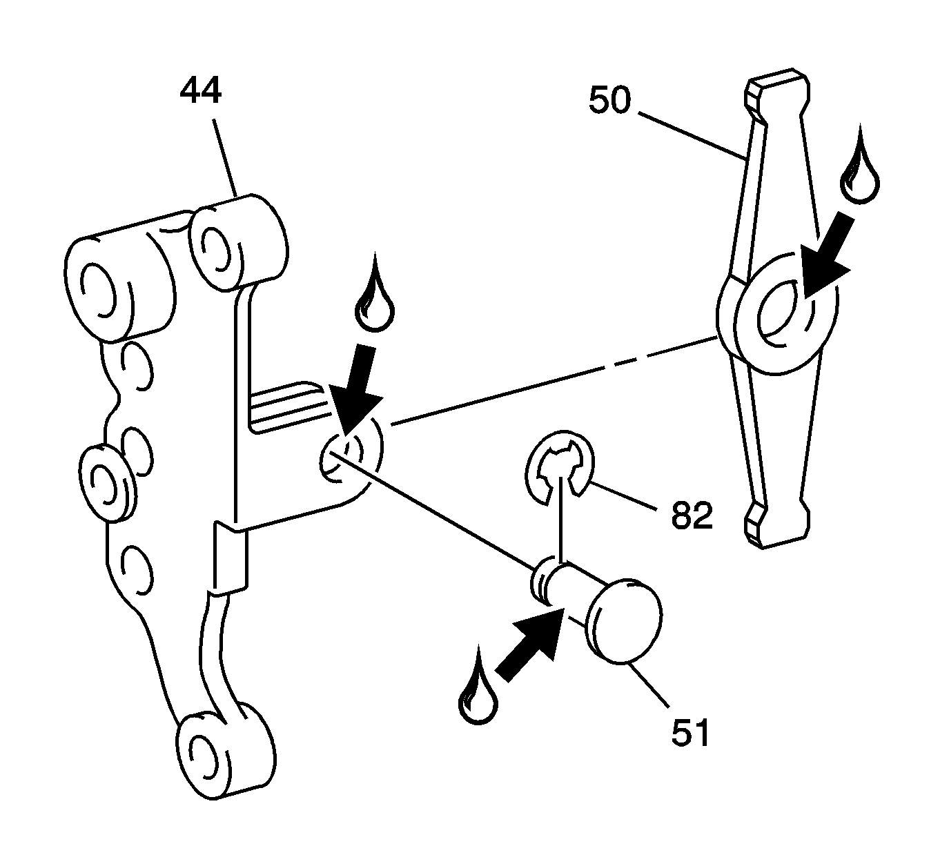
- Remove the E-ring (82) and pull the control select arm pin (51) from the shift control lever bracket (44).
- Remove the control select arm (50) from the shift control lever bracket (44).
- Inspect the cam (45), shift forks (49), (52), (63) and assembly (46) for:
- Measure the fork width and sleeve groove width for wear. If synchronizer sleeve to shift fork width clearance exceeds the maximum, replace the synchronizer sleeve and/or shift fork. Refer to Transmission Clearance Specifications and see Synchronizer Sleeve to Shift Fork Clearance - Maximum Clearance table.
- Inspect the detent lever (62), assembly (56 and 57), shift shaft (59) and control lever (56) for:
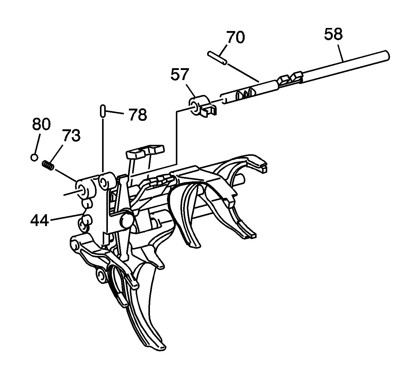
Important: The shift detent ball (80) and spring (73) will come out of the shift control lever when the 1st/2nd shift shaft (58) is removed.
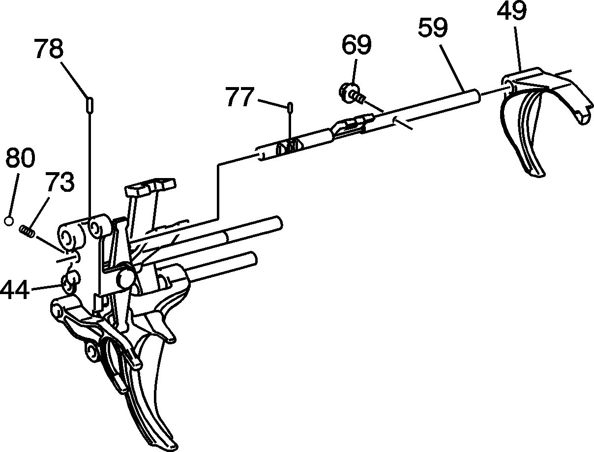
Important: The shift detent ball (80) and spring (73) will come out of the shift control lever bracket (44) when the 3rd/4th shift shaft (59) is removed.
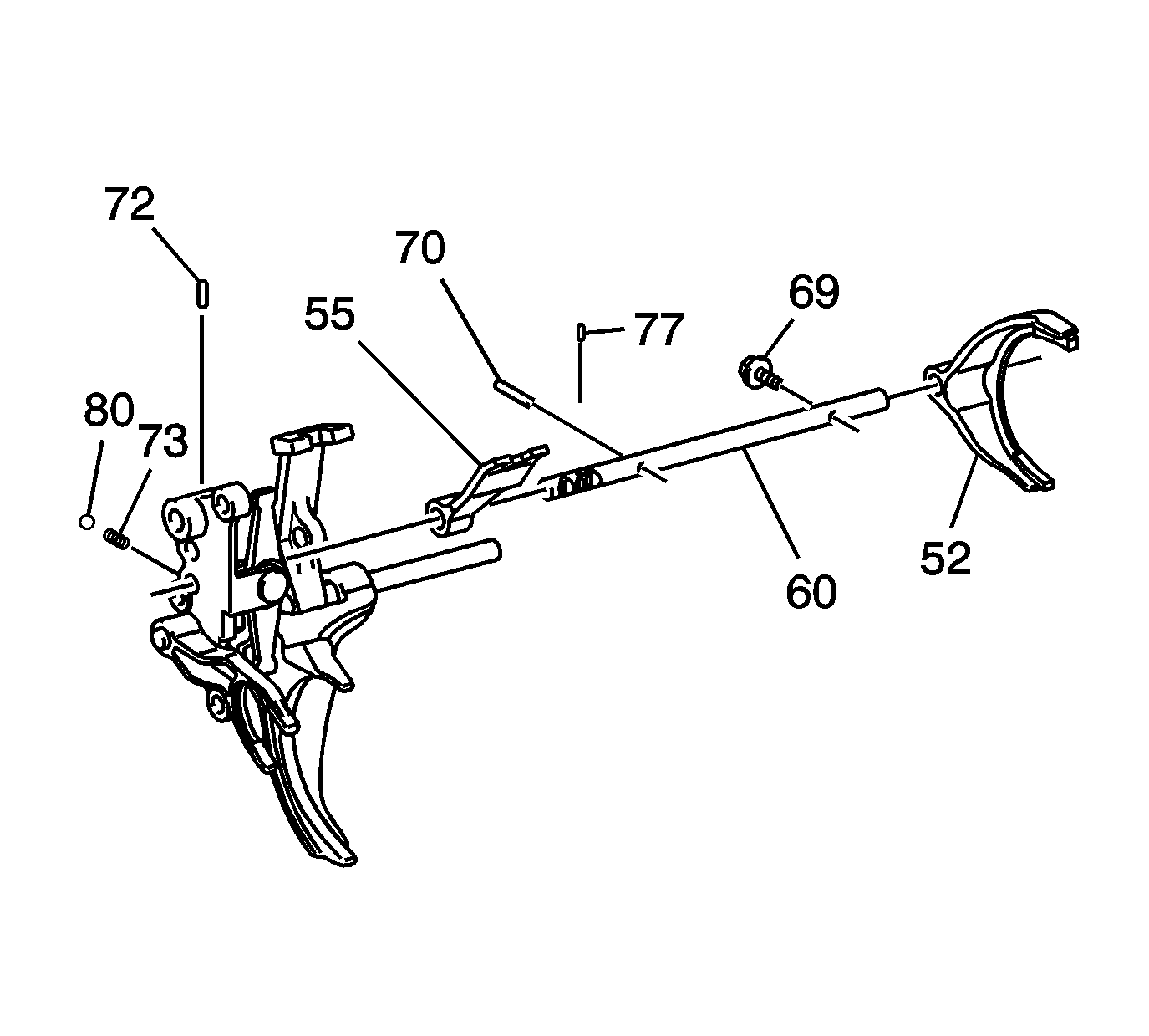
Important: The shift detent ball (80) and spring (73) will come out of the shift control lever bracket (44) when the 5th/6th shift shaft (60) is removed.
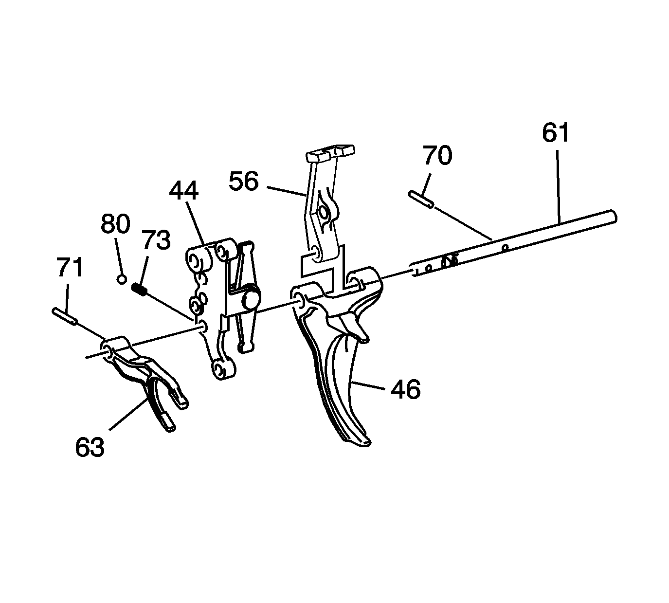
Important: The shift detent ball (80) and spring (73) will come out of the shift control lever bracket (44) when the reverse shift shaft (61) is removed.
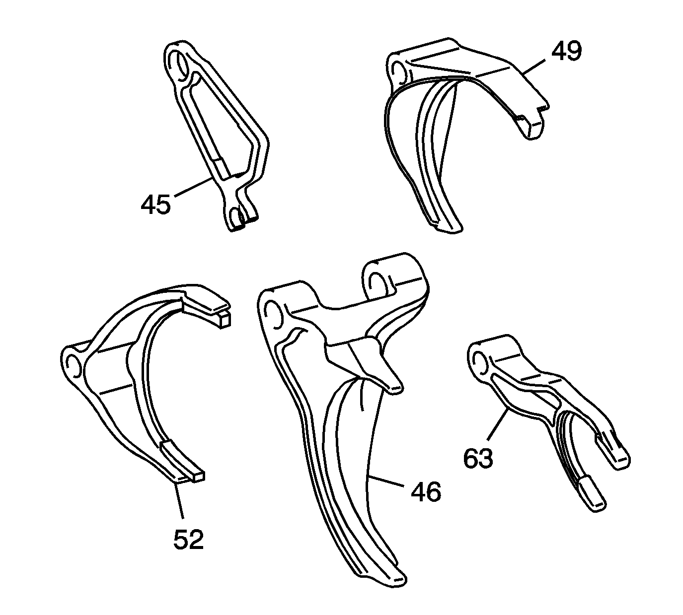
| • | Bent fork |
| • | Hole for wear |
| • | Cracks |
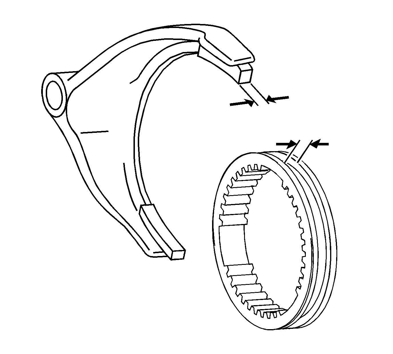
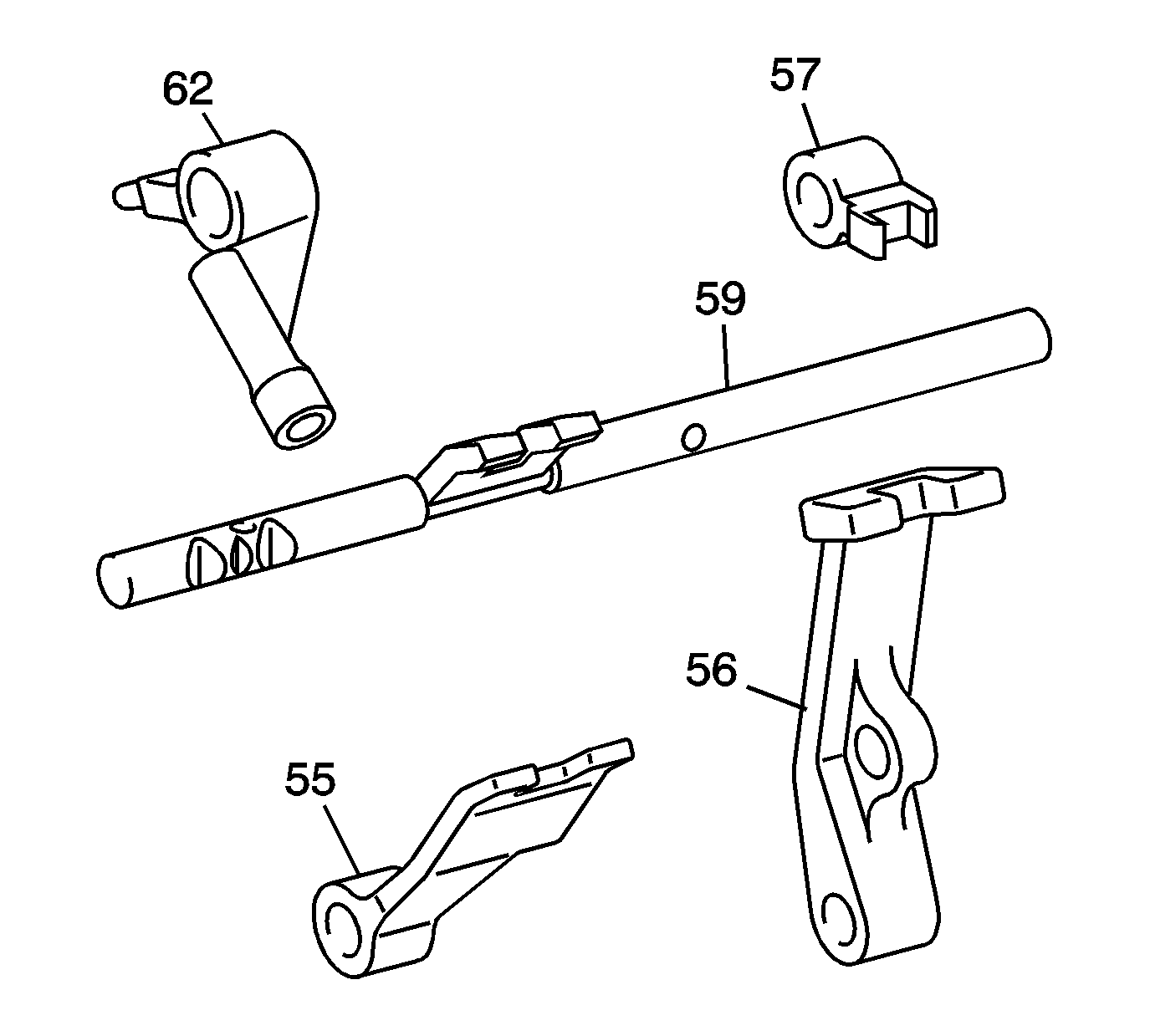
| • | Bent fork |
| • | Hole for wear |
| • | Cracks |
Shift Shaft and Shift Forks Assemble
- Apply lubricant GM P/N 89021806 (Canadian P/N 89021807) and install the control select arm (50) into the shift control lever bracket (44).
- Apply lubricant and install the control select arm pin (51).
- Install the E-ring (82).
- Apply lubricant GM P/N 89021806 (Canadian P/N 89021807) and slide the intl shift control lever (56) and 1st/2nd shift fork assembly (46) onto the reverse shift shaft (61). Install the slotted pin (70) into the lever (56).
- Install the shift control lever bracket (44) onto the reverse shift shaft (61).
- Slide the reverse shift fork (63) onto the reverse shift shaft (61). Install the slotted pin (71) into the reverse shift fork (63).
- Install the spring (73) and shift detent ball (80) into the bracket (44).
- Install the pin (72) into the shift control lever bracket (44).
- Install the pin (77) into the 5th/6th shift shaft (60).
- Install the 5th/6th shaft (60) into the hole in the shift lever assembly (55).
- Install a NEW bolt (69) into the shift lever assembly (55).
- Install the 5th/6th shift shaft (60) into the shift control lever bracket (44).
- Apply lubricant and slide the 3rd/4th shift fork (49) onto the 3rd/4th shift shaft (59). Install a NEW bolt (69) into the 3rd/4th shift fork (49).
- Insert the spring (73) and the shift detent ball (80) into the shift control lever bracket (44).
- Install the pin (77) into the 3rd/4th shift shaft (59).
- Install pin (78) into the shift control lever bracket (44).
- Install the 3rd/4th shift shaft (59) into the shift control lever (44).
- Install the spring (73) and detent ball (80) into the shift control lever bracket (44).
- Install the pin (78) into the shift control lever bracket (44).
- Install the groove of select control lever assembly (57) into the projection of the control select arm (50).
- Slide the 1st/2nd shift shaft (58) into the shift control lever (57), and the shift control lever bracket (44).
- Install pin (70) into the 1st/2nd shift shaft (58).
- Install the 5th/6th shift fork (52) onto the 5th/6th shift shaft (60) and retain with a new bolt (69).
- Slide the shift shaft detent lever (62) onto the shift control shaft (66).
- Install a NEW bolt (76) into the shift shaft detent lever (62).
- Apply lubricant and insert the shift shaft detent spring (74) and the shift shaft detent (67) into the lever (62).
- Apply lubricant and slide the shift shaft detent cam (45) onto the shift control shaft (66).
- Insert the assembled shift shaft detent lever (62, 74, 67) into the opening in the shift shaft detent cam (45).
- Install the dynamic damper weight (101) onto the shift control shaft (66).
- Insert the pin (100) into the dynamic damper weight (101).
- Check the function of assembled components. The shift shaft detent (67) should slide on the shift shaft detent cam (45).
Tighten
Tighten the bolt to 19.5 N·m (14 lb ft).
Tighten
Tighten the bolt to 19.5 N·m (14 lb ft).
Tighten
Tighten the bolt to 19.5 N·m (14 lb ft).
Tighten
Tighten the bolt to 19.5 N·m (14 lb ft).
