Tools Required
| • | DT-47735 Pinion Flange Holder |
| • | J 35467 One-Way Clutch Tester |
| • | J 44731 Input Shaft Seal Installer |
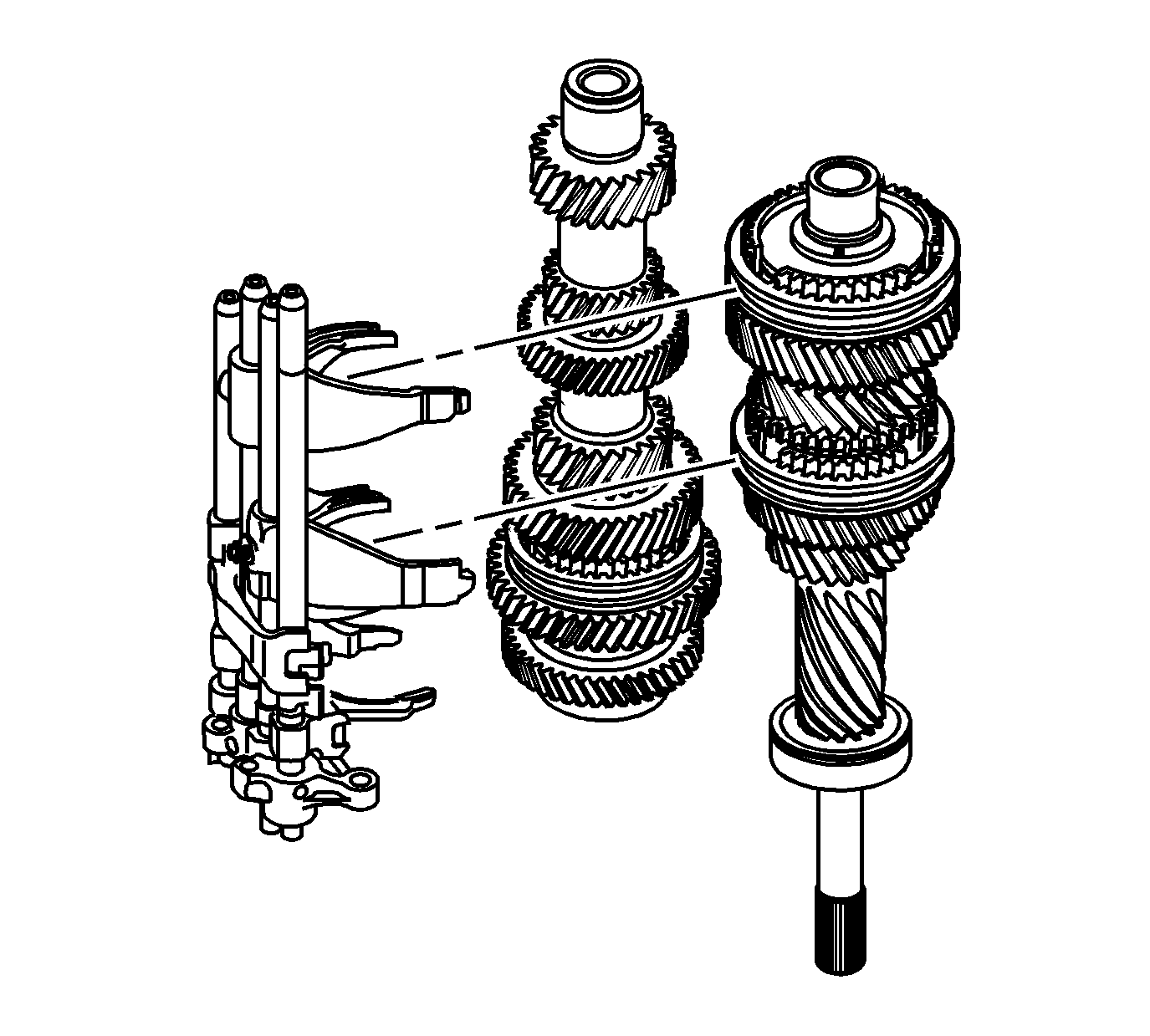
- Apply lubricant GM P/N 89021806 (Canadian P/N 89021807) to each gear shift fork and gear shift head. Join the shift rail assembly to the input shaft and countershaft assembly.
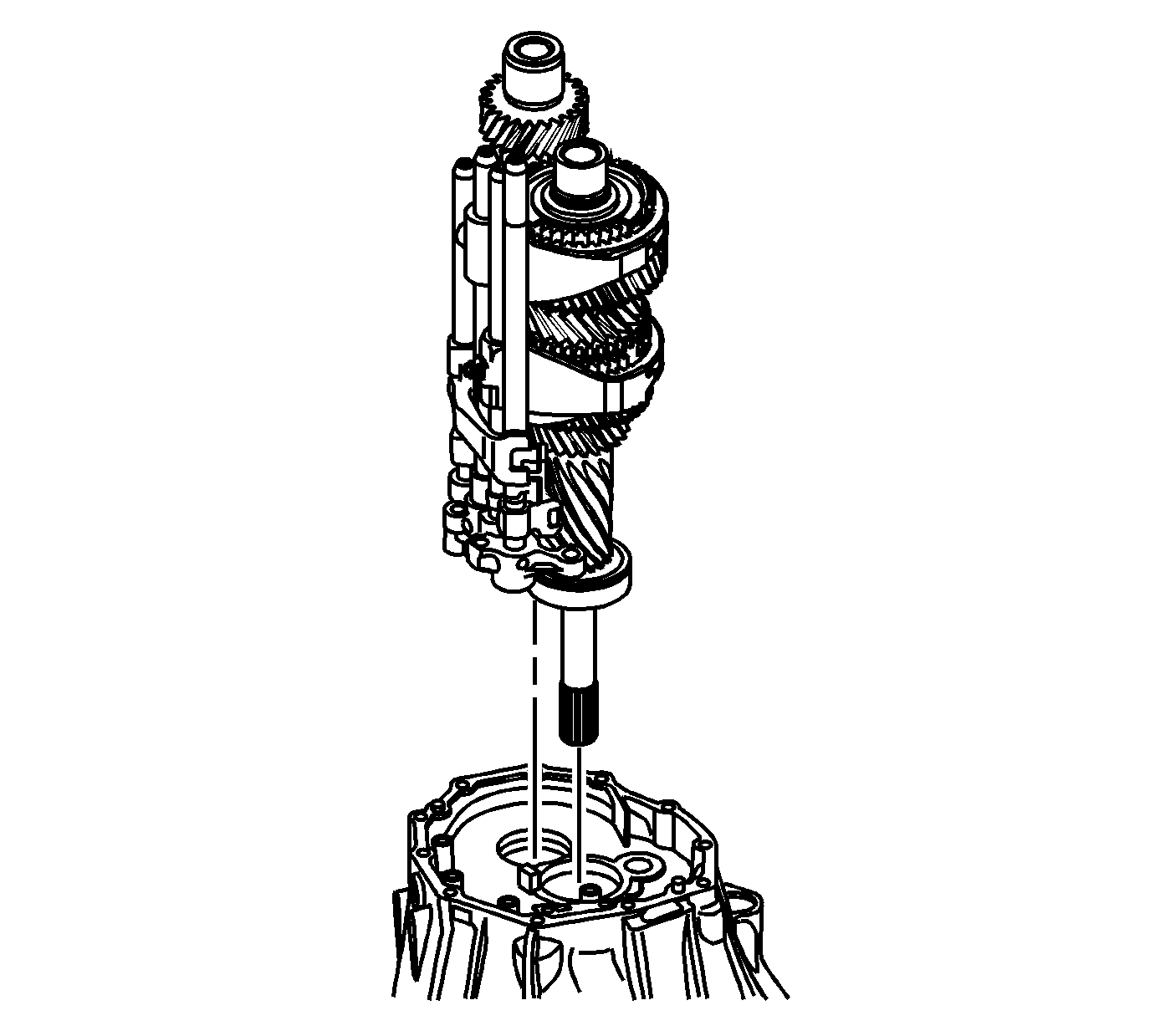
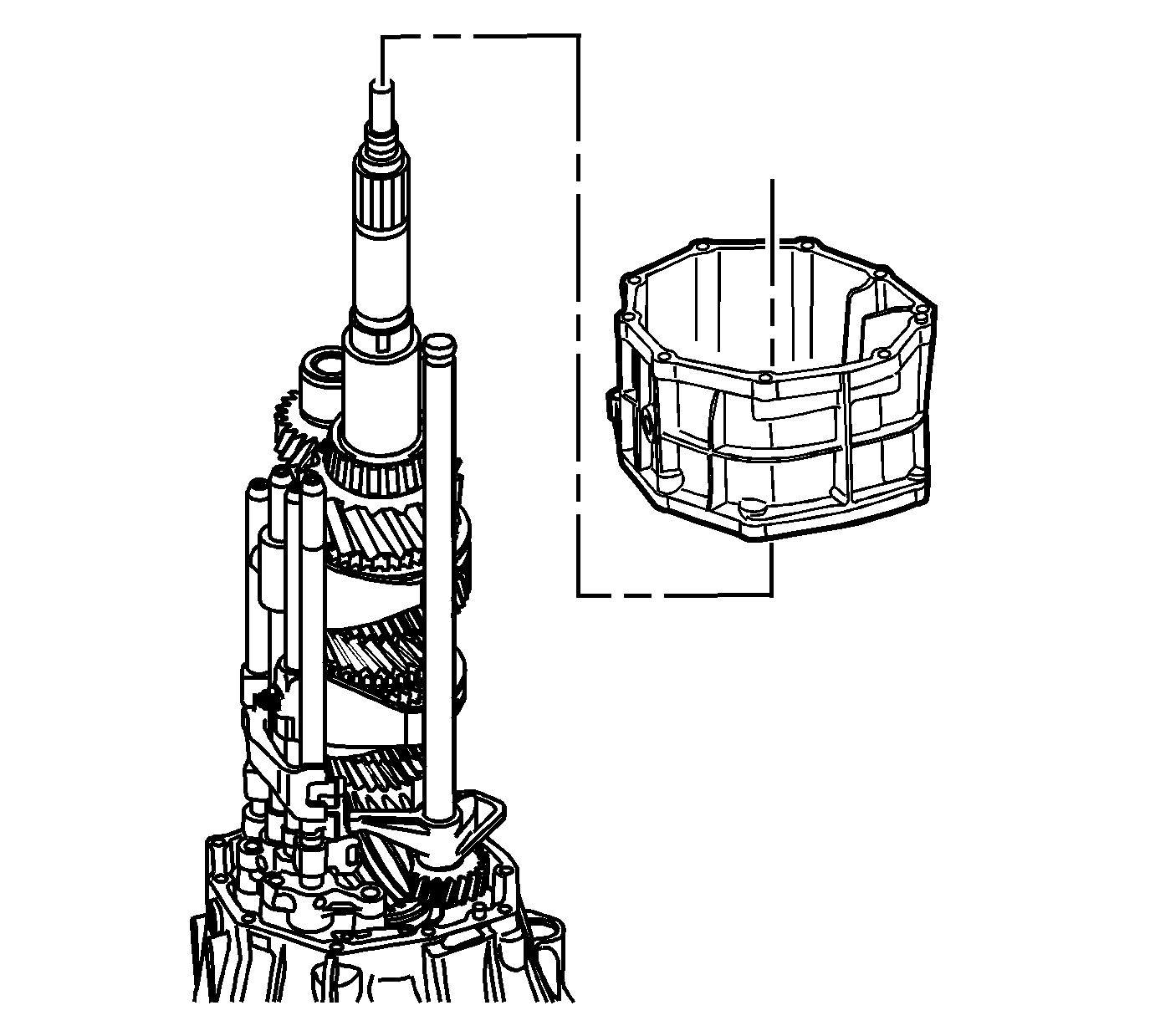
- Install the input shaft, countershaft and shift rails as an assembly in the clutch housing.
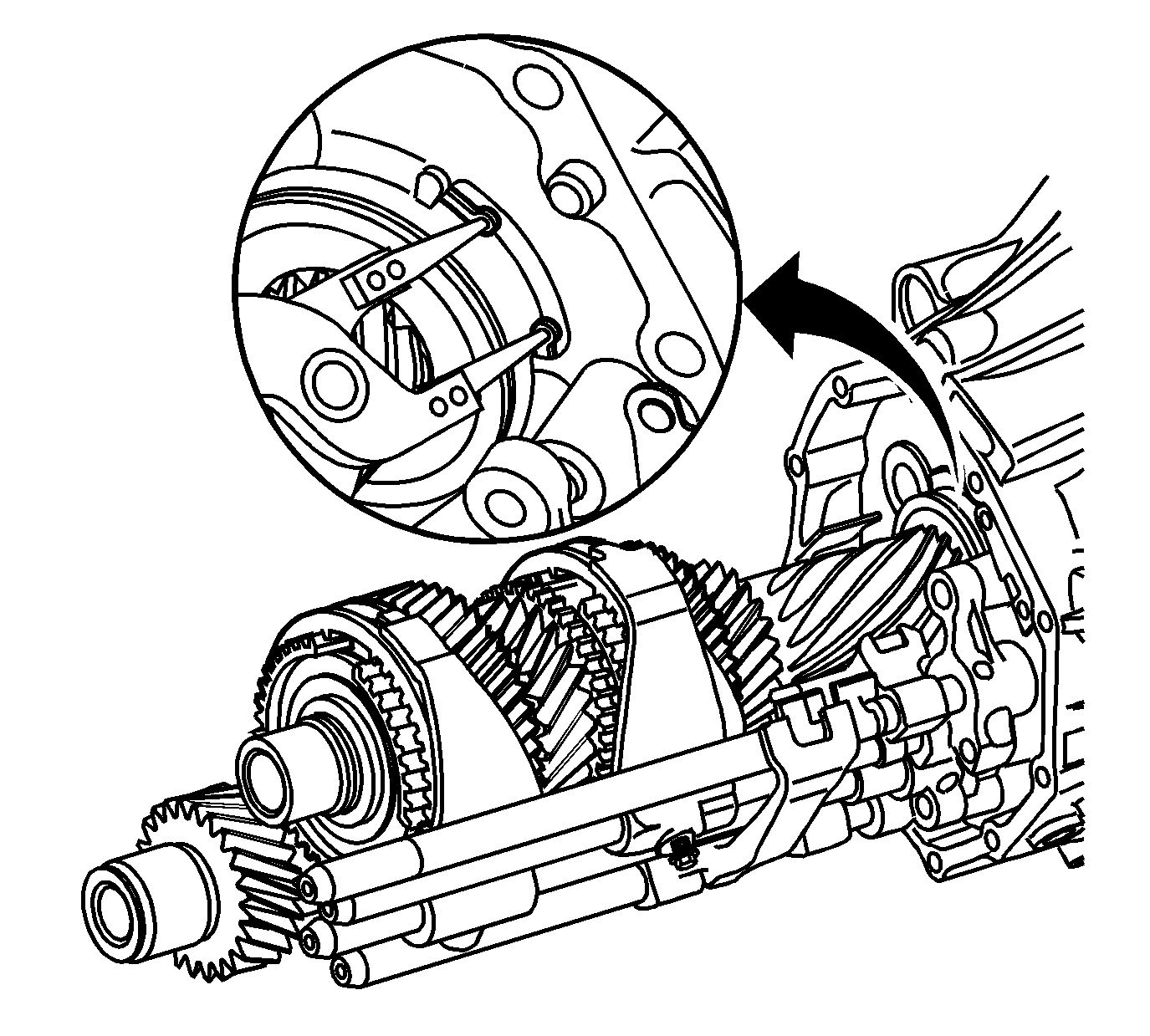
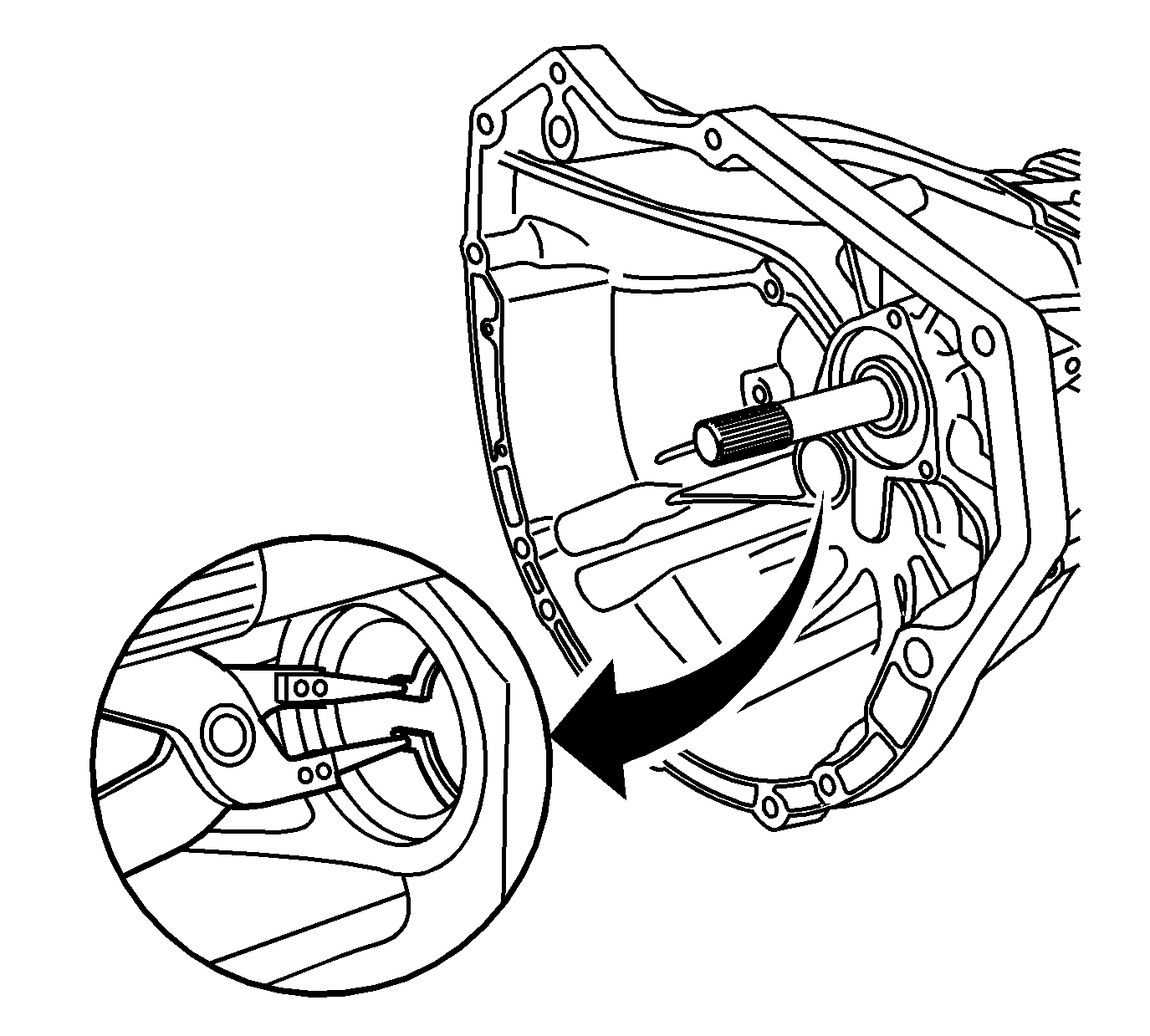
- Install the snap ring into the groove of the input shaft radial ball bearing.
- Install the snap ring into the groove of the countershaft radial ball bearing.
- Apply threadlocker GM P/N 12345382 (Canadian P/N 10953489) or equivalent to the shift rail bolts.
- Install the 4 shift rail bolts.
- Apply lubricant GM P/N 89021806 (Canadian P/N 89021807) and install the following components:
- Apply lubricant GM P/N 89021806 (Canadian P/N 89021807) and install the input shaft bearing (137), blocking ring (121) and the rear output shaft (111).
- Apply sealer GM P/N 89020326 (Canadian P/N 89021188) or equivalent to the interface of either case.
- Install the shift shaft selector lever.
- Apply sealer GM P/N 89020326 (Canadian P/N 89021188) or equivalent to the interface of either case.
- Apply lubricant GM P/N 89021806 (Canadian P/N 89021807) to the shift and select lever shaft bearing.
- Install the intermediate case housing.
- Install the 8 bolts from the clutch housing and the 3 bolts from the middle case.
- Install the oil trough pipe (19).
- Install a NEW gasket (32) and the bolt (35) to secure the reverse idler shaft.
- Install the oil trough (20) and the 2 oil trough bolts (37).
- Apply lubricant GM P/N 89021806 (Canadian P/N 89021807) to the following components:
- Apply lubricant GM P/N 89021806 (Canadian P/N 89021807) to the following components:
- Apply sealer GM P/N 89020326 (Canadian P/N 89021188) or equivalent to the interface of either case.
- Install the rear case housing.
- Install the 10 bolts (27) and retainer (209) to the rear case housing.
- Apply lubricant GM P/N 89021806 (Canadian P/N 89021807) and install the lock ball pin (68).
- Install the spring (75) and a NEW plug (36).
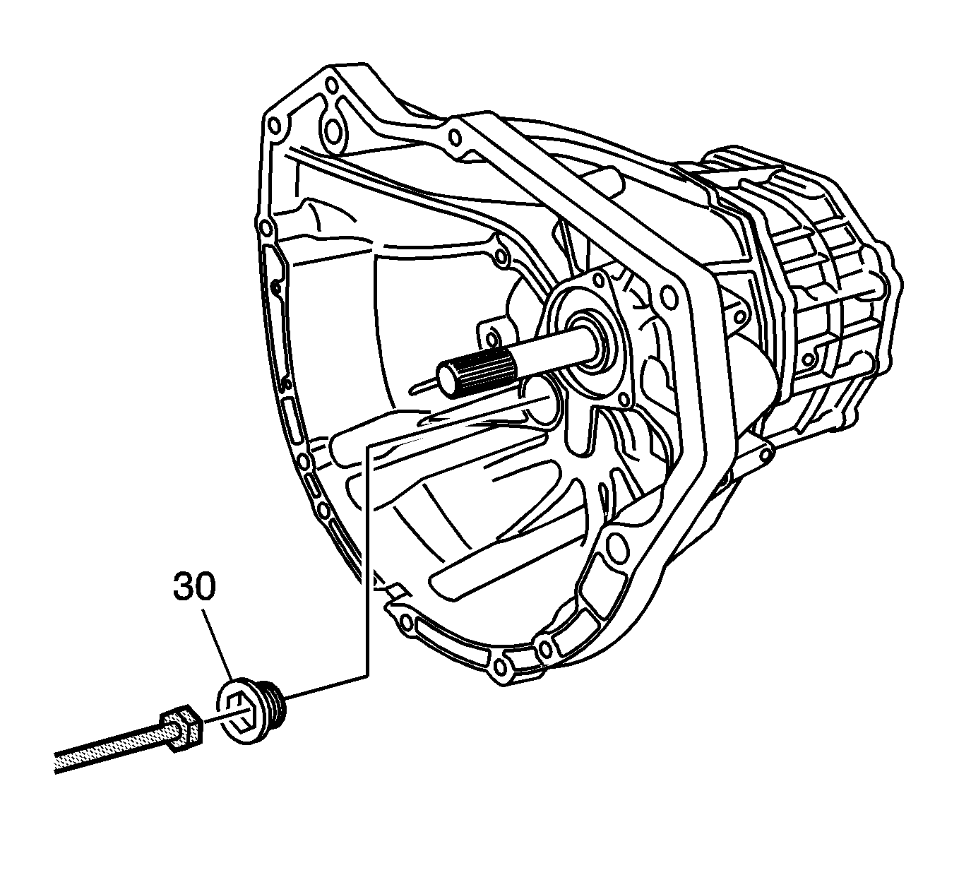
- Using J 35467 , install a NEW clutch housing hole plug (30) into the clutch housing.
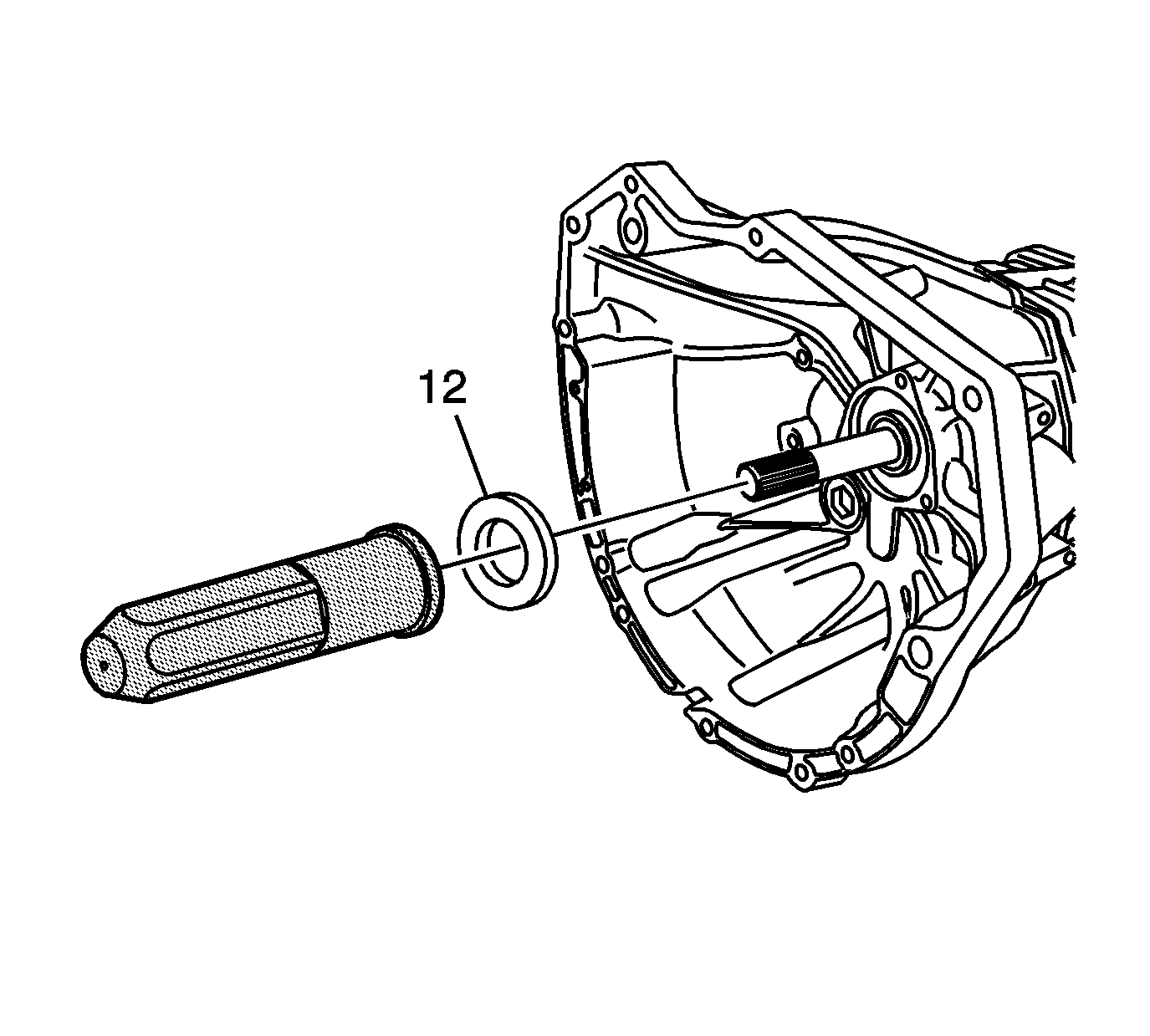
- Using J 44731 , install a NEW input shaft seal (12).
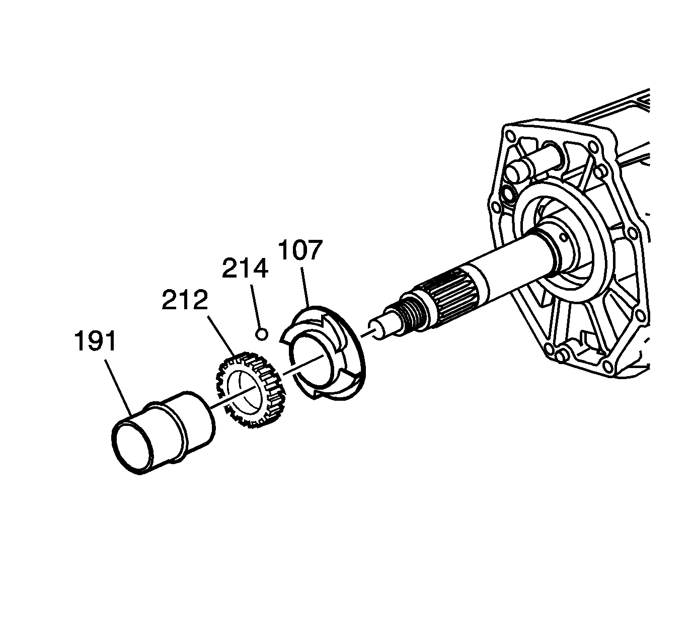
- Align and install the main shaft bearing oil slinger (107).
- Grease and install the locking ball (214).
- Align and install the vehicle speed sensor drive gear (212).
- Install a NEW rear output shaft rear bearing spacer (191).
- Apply sealer GM P/N 89020326 (Canadian P/N 89021188) or equivalent to the interface of either case.
- Install the rear extension housing.
- Install the 8 bolts (93) into the rear extension housing (86).
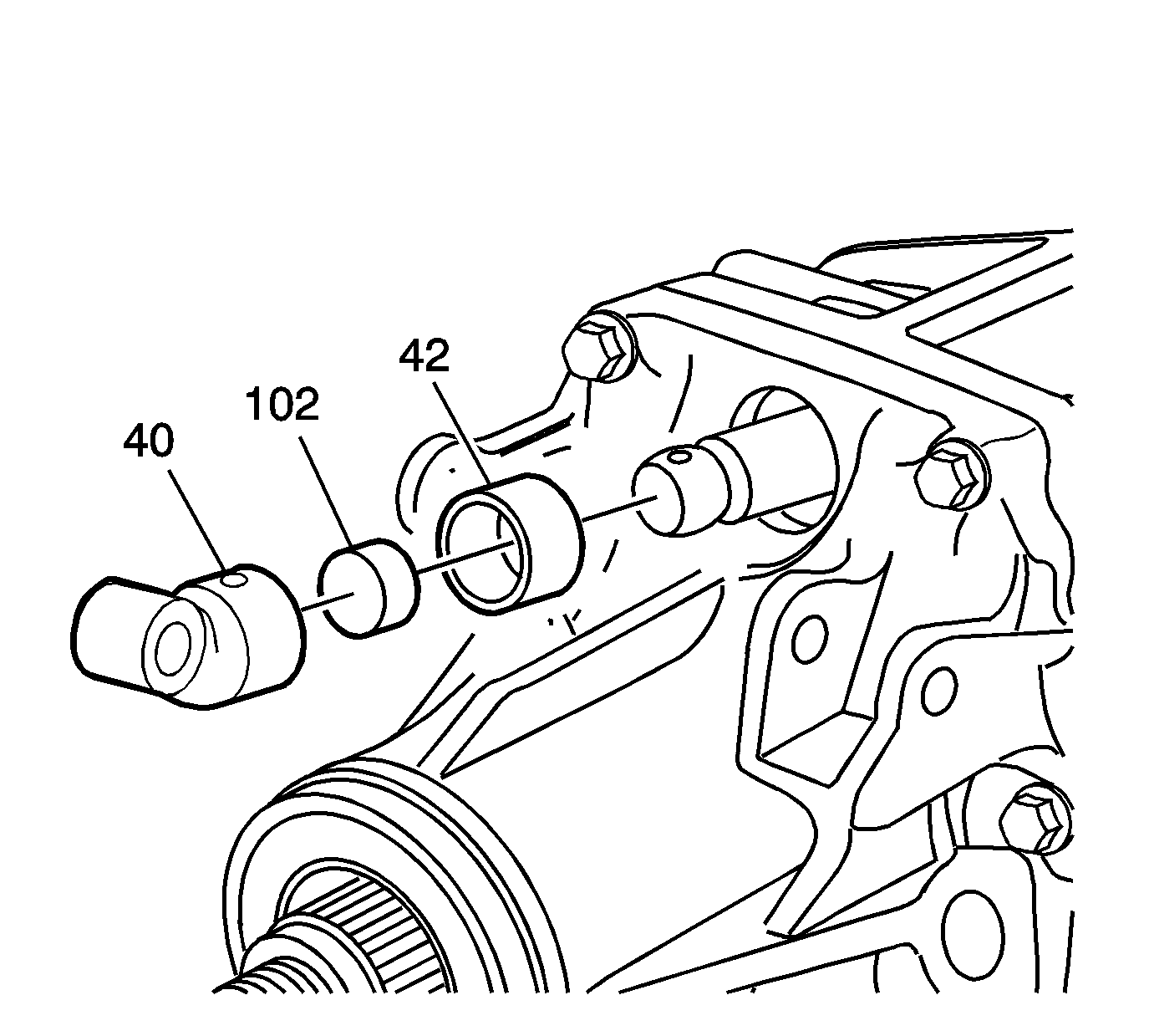
- Install a NEW select shift lever retainer (42), the damper (102) and shift lever rod universal joint (40) into the end of the shift selector.
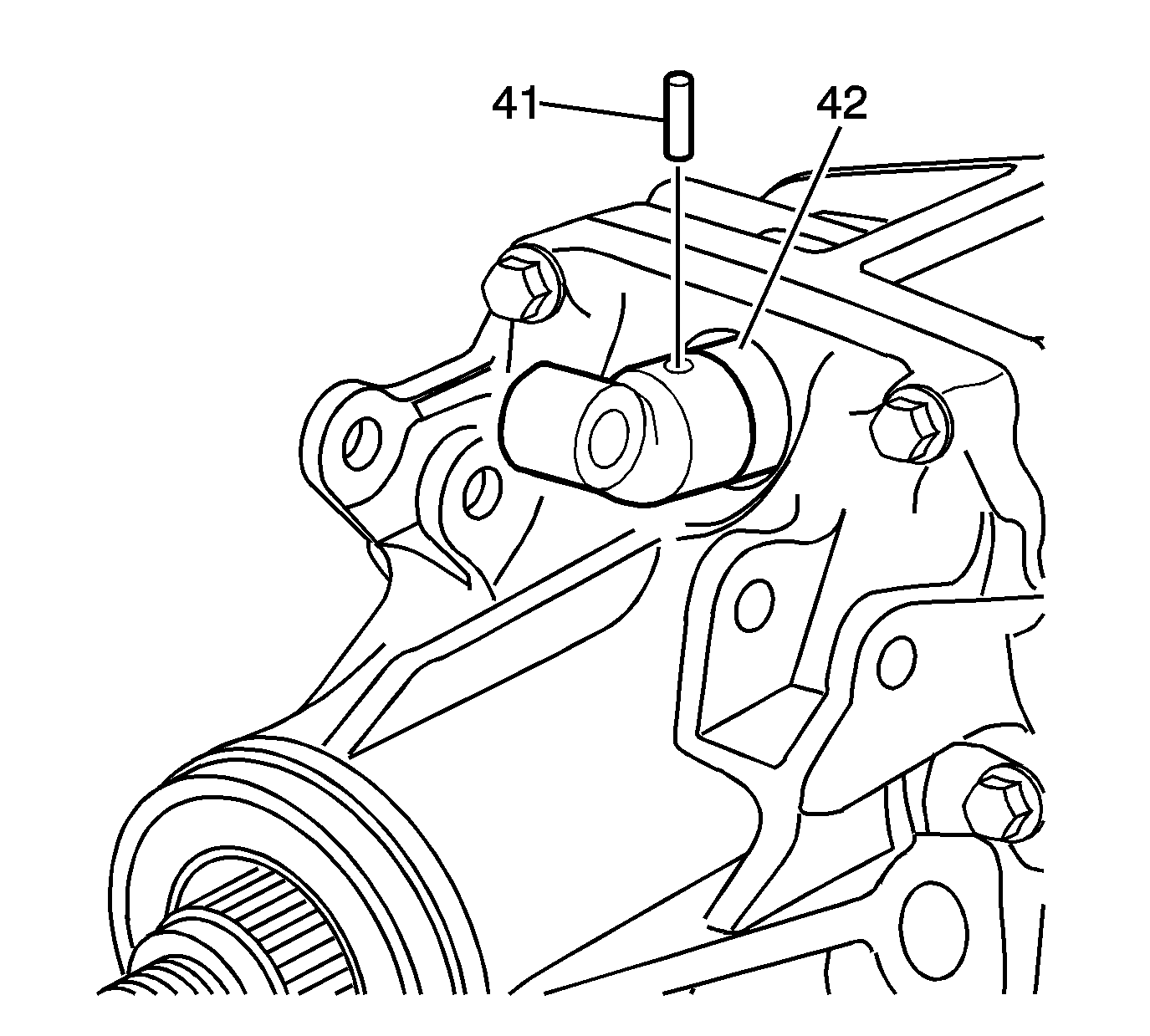
- Install the shift lever pin (41).
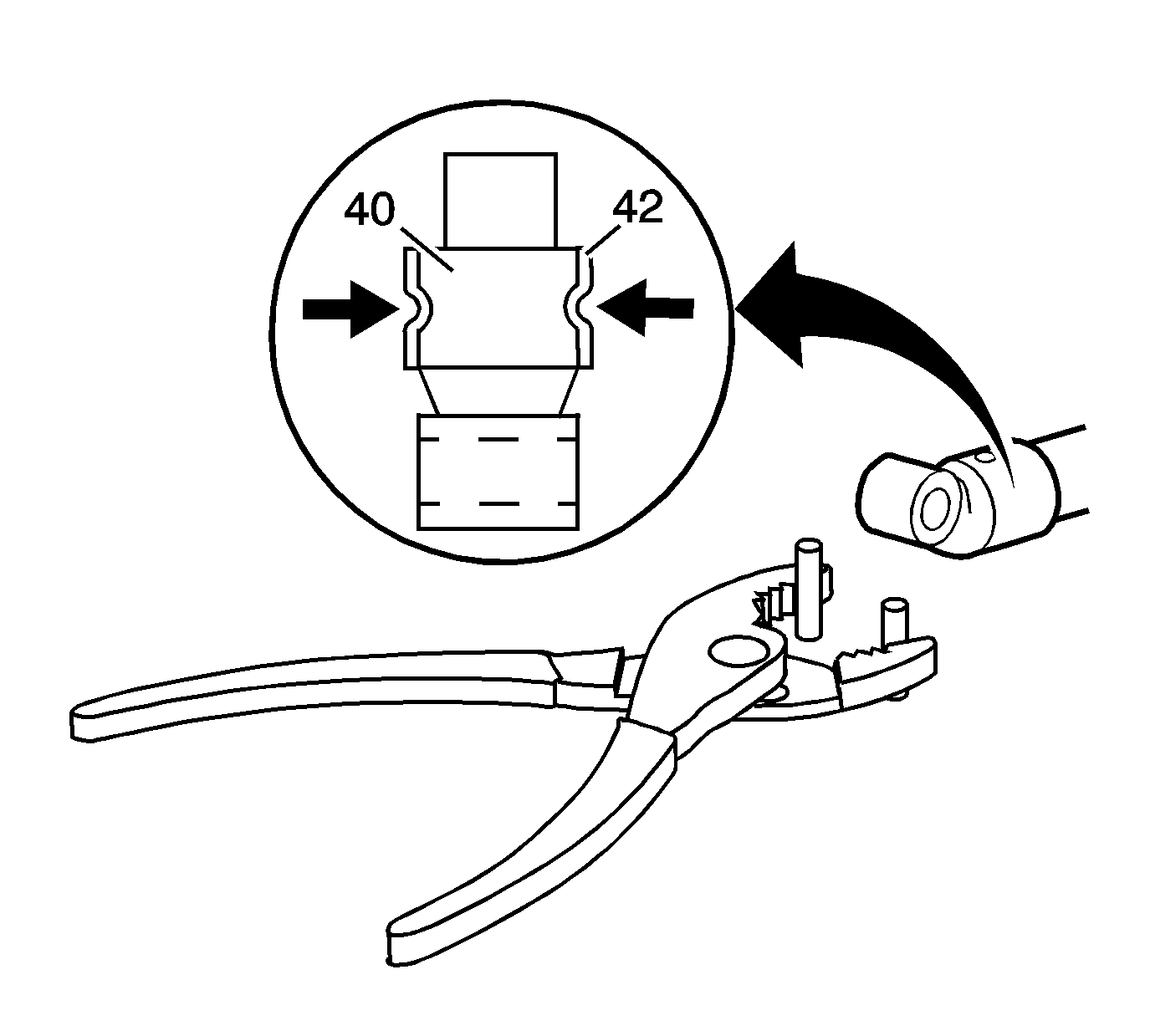
- With suitable pliers, rotate the shift lever retainer (42) backward.
- Stake the retainer (42) in place using pliers and 2 roll pins held in place with assembly lube.
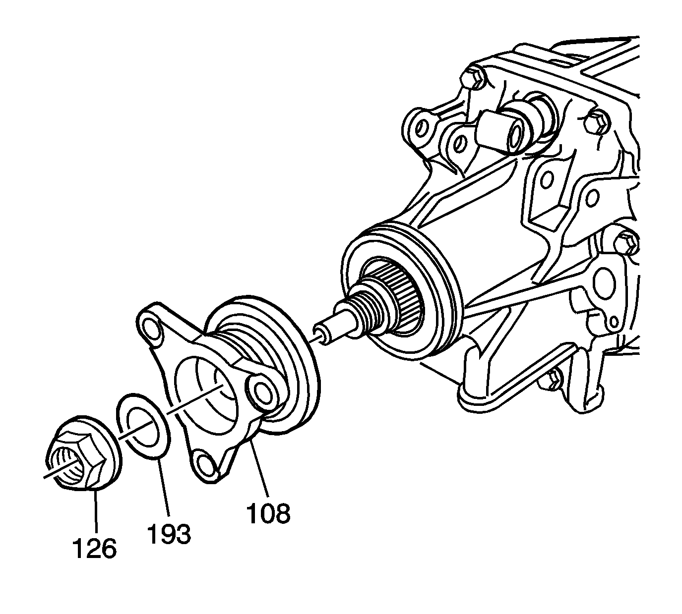
- Install the propshaft flange (108).
- Grease and install a NEW propshaft flange fluid seal (193).
- Install a NEW propshaft flange nut (126).
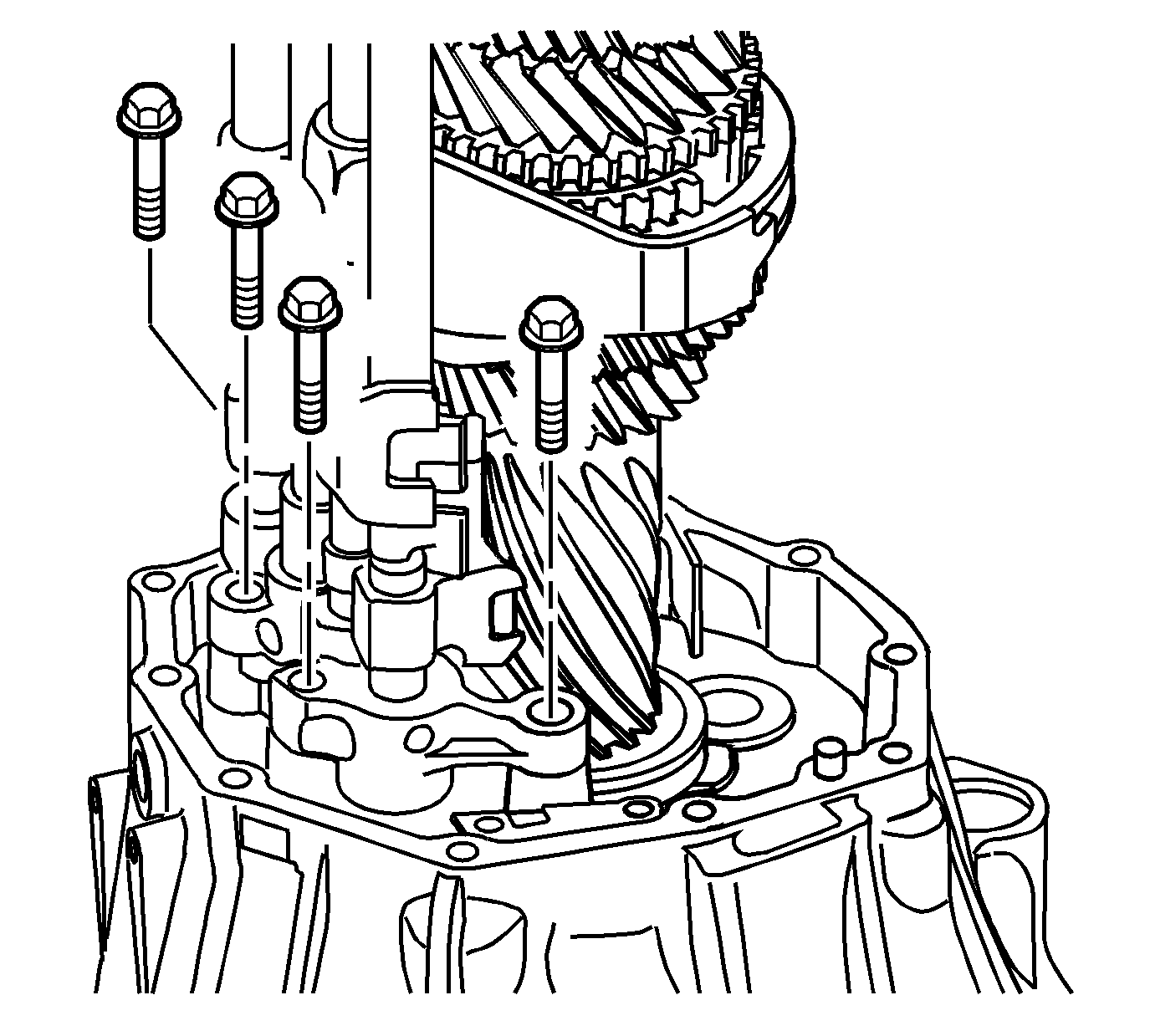
Notice: Refer to Fastener Notice in the Preface section.
Tighten
Tighten the bolts to 21 N·m (15 lb ft).
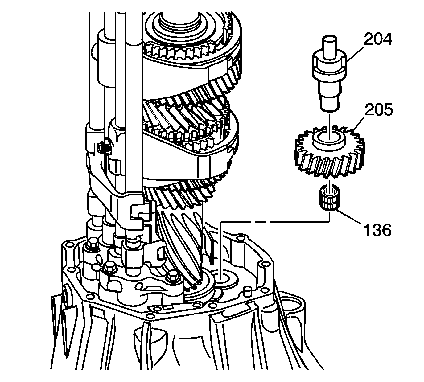
Important: During alignment, ensure that the thread hole of the reverse idler gear shaft (204) aligns with the thread hole of the middle case.
| • | the reverse idler gear bearing (136) |
| • | the reverse idler gear (205) with the higher boss facing the rear |
| • | the reverse idler gear shaft (204) with its hole facing outward |
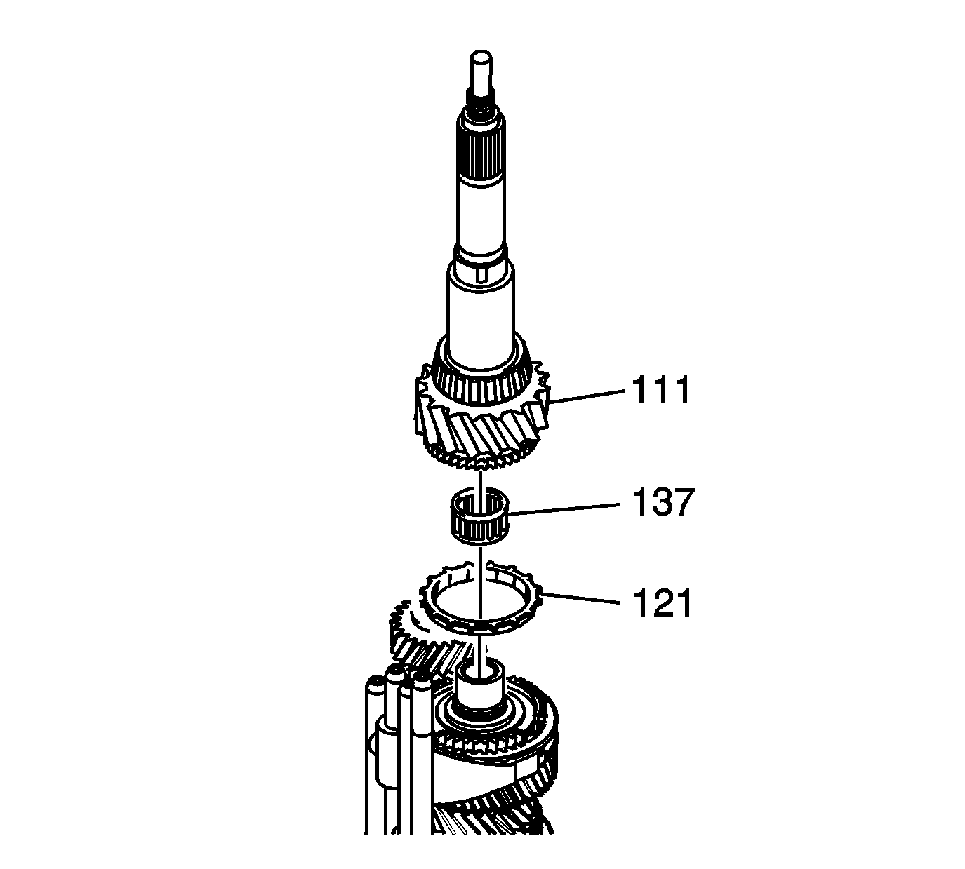
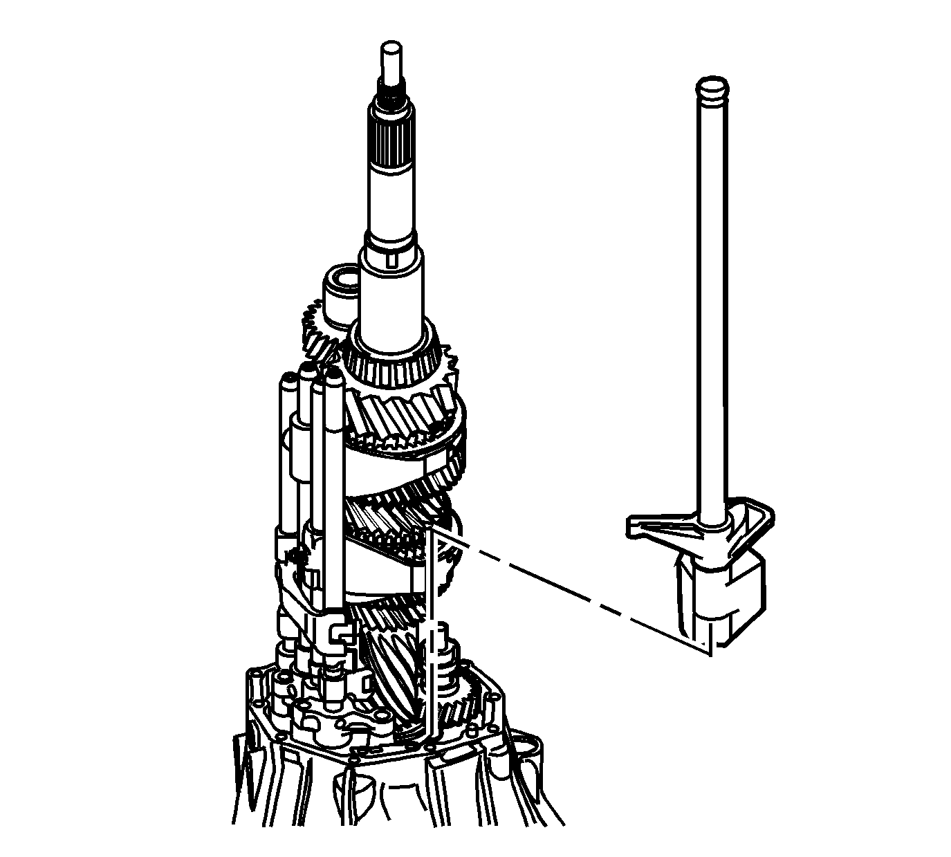
Notice: Refer to Machined Surface Damage Notice in the Preface section.
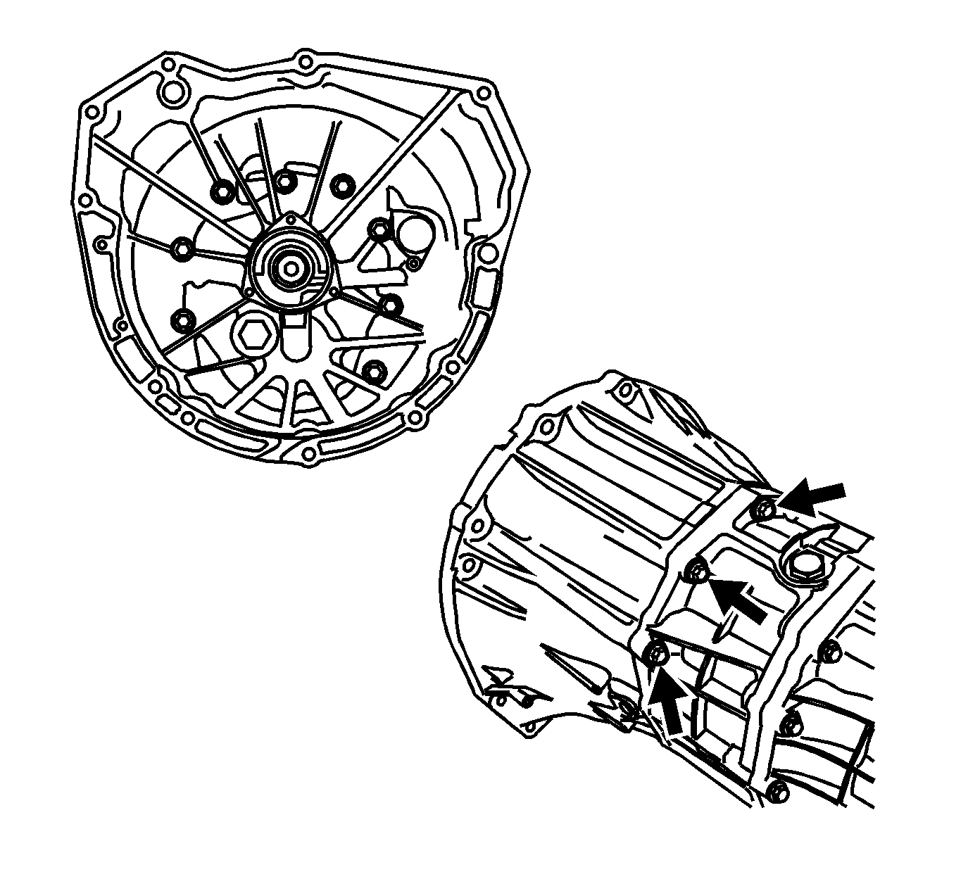
Tighten
Tighten the bolts to 40 N·m (30 lb ft)
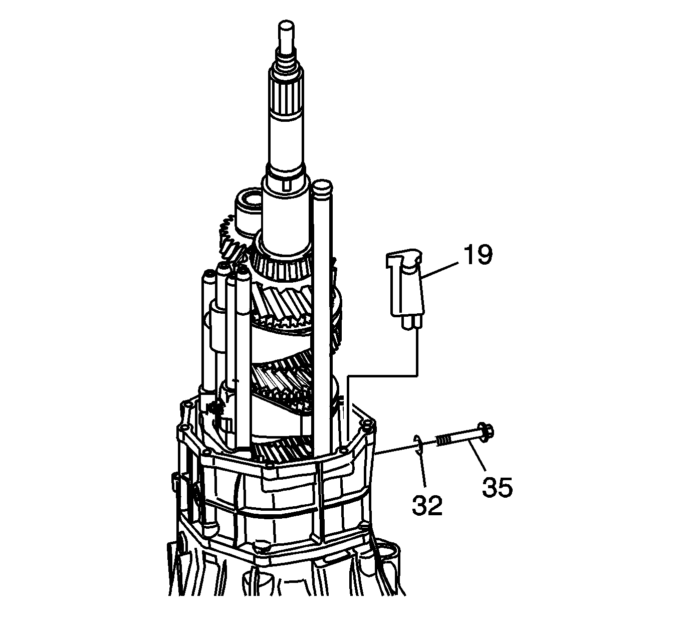
Tighten
Tighten the bolt to 40 N·m (30 lb ft)
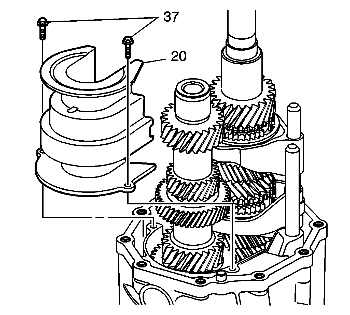
Tighten
Tighten the bolts to 8.5 N·m (75 lb in)
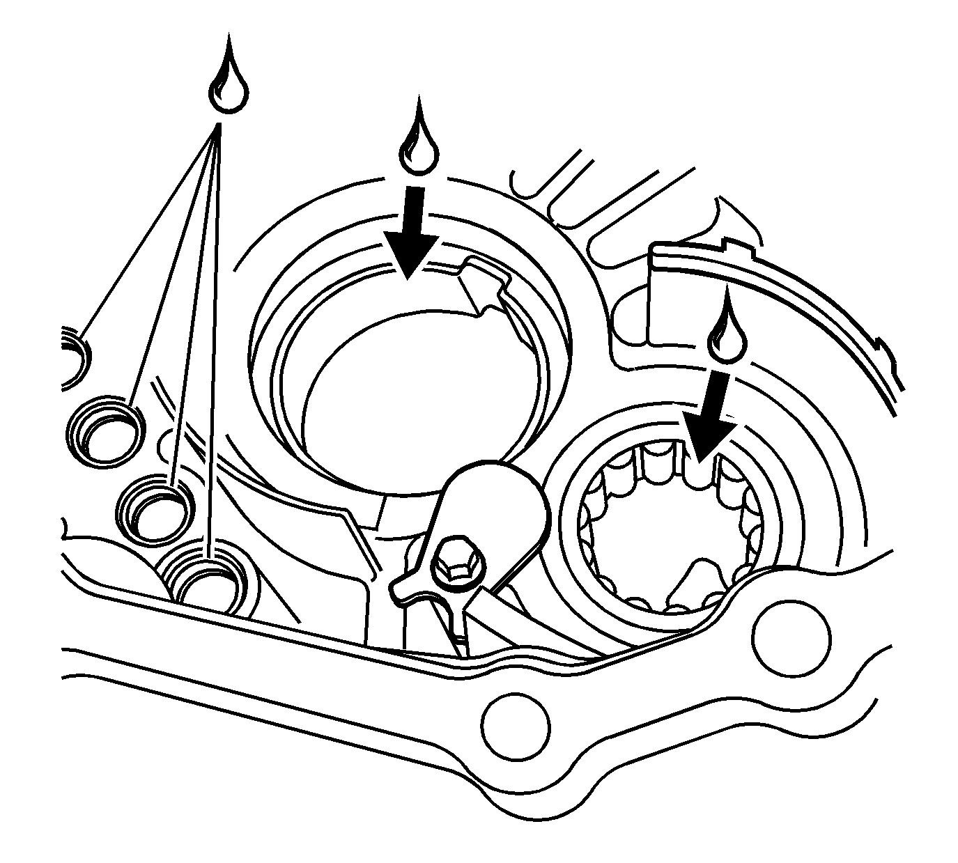
| • | the tapered roller bearing outer race |
| • | the cylindrical roller bearing |
| • | the control sub-assembly holes |
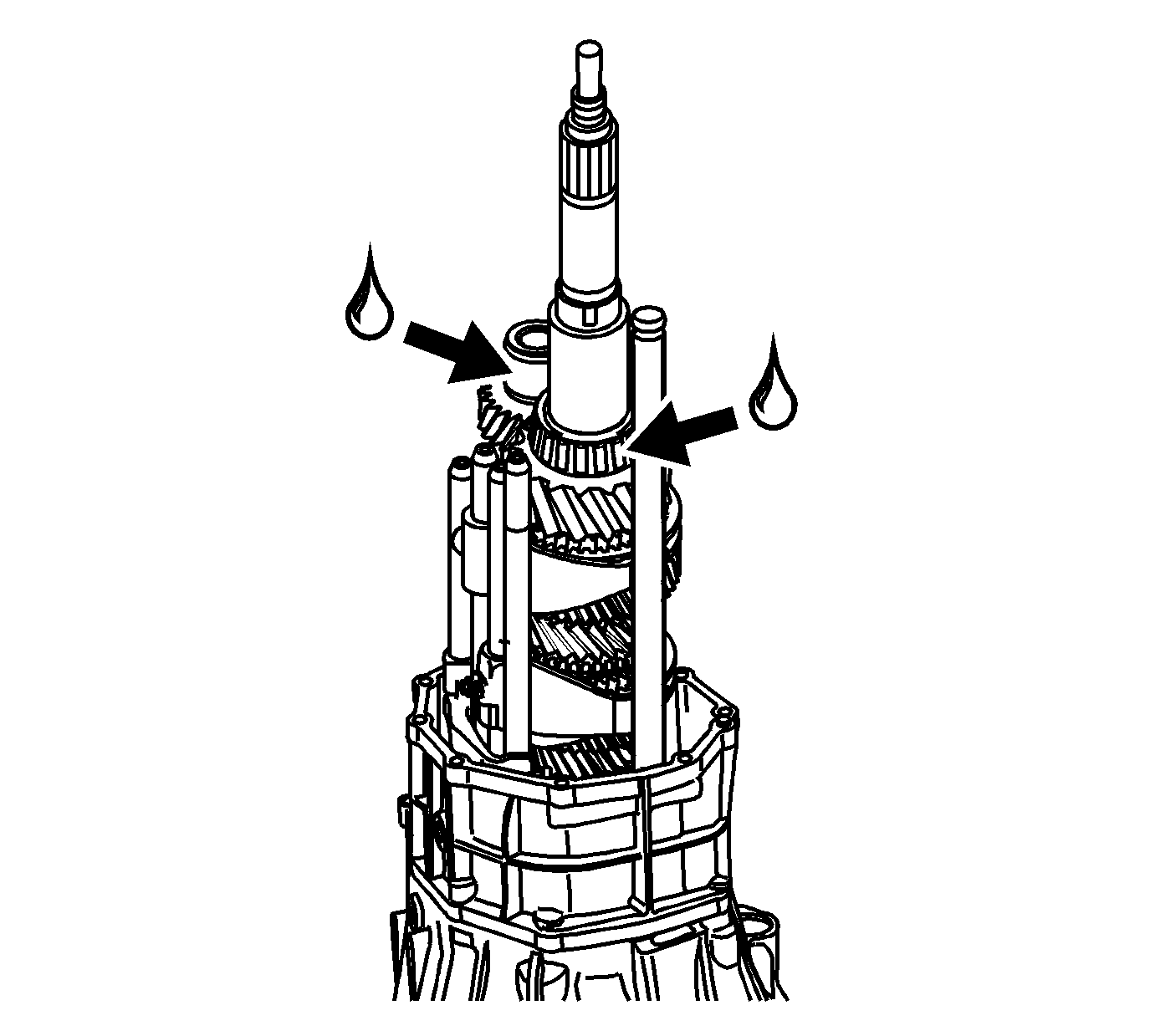
| • | the tapered roller bearing of the output shaft |
| • | the cylindrical roller bearing inner race of counter gear |
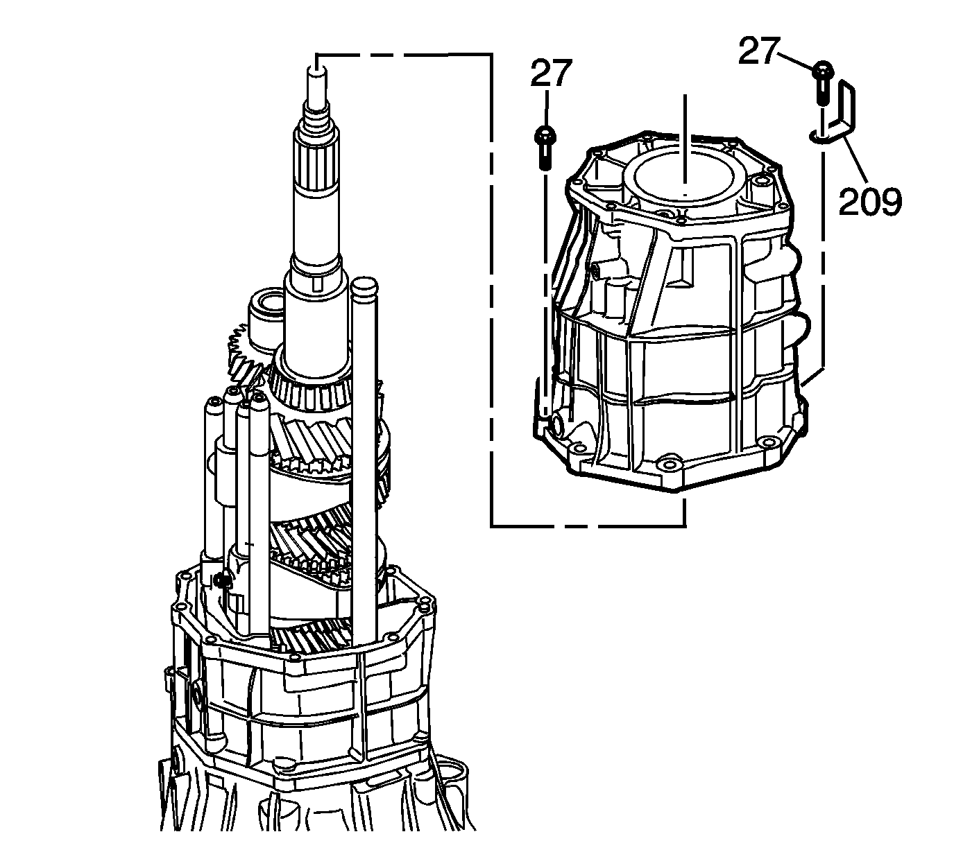
Notice: Refer to Machined Surface Damage Notice in the Preface section.
Tighten
Tighten the bolts to 40 N·m (30 lb ft)
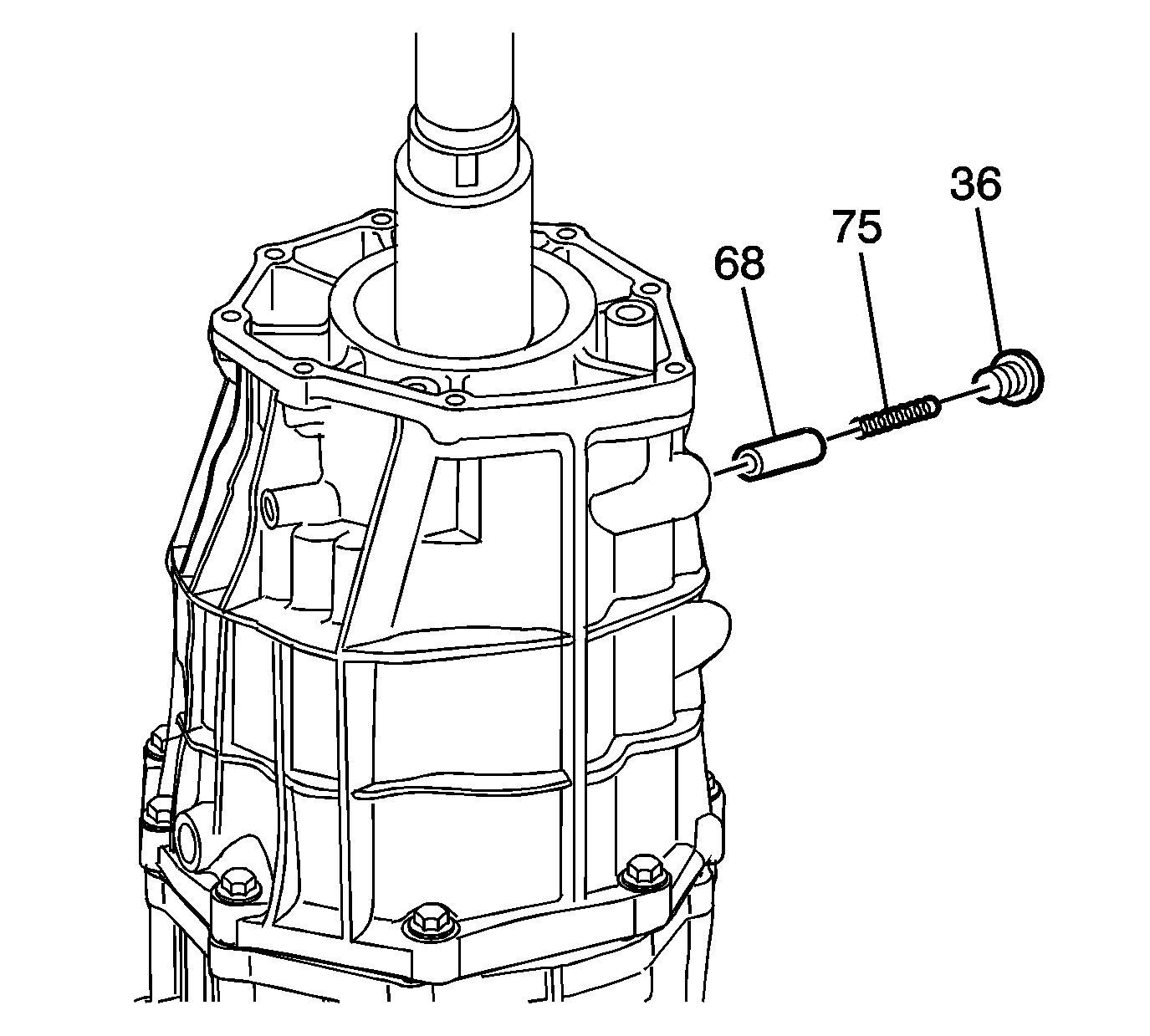
Tighten
Tighten the plug to 24.5 N·m (18 lb ft)
Tighten
Tighten the bolt to 39.3 N·m (29 lb ft).
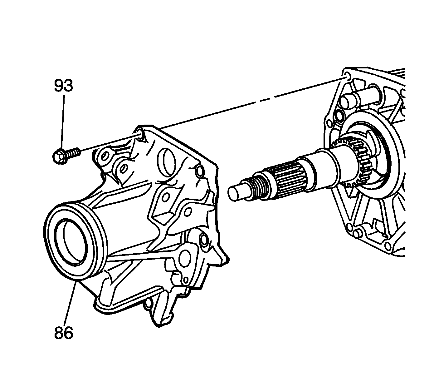
Tighten
Tighten the bolts to 29 N·m (21 lb ft)
Preload Adjustment Procedure
- Shift the transmission into any gear.
- Attach DT-47735 to the output flange.
- Hold DT-47735 in order to prevent the output flange from rotating. Install and tighten the output flange nut. Tighten until the looseness is minimum.
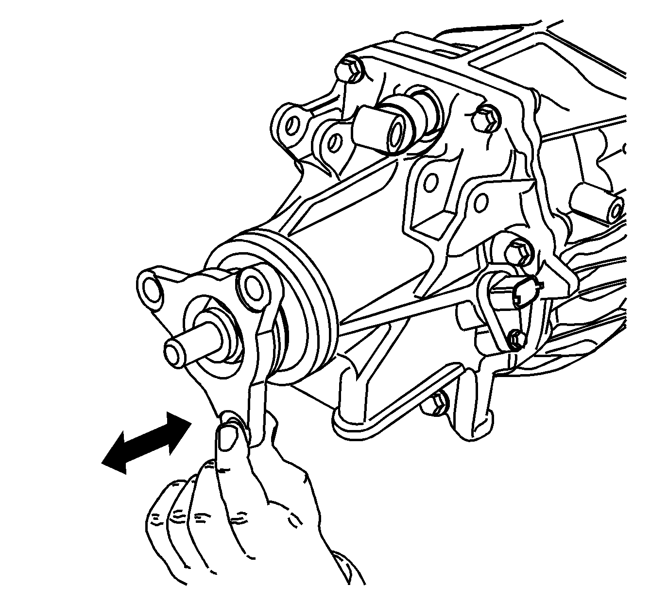
- Verify looseness by shaking the output shaft longitudinally.
- Remove DT-47735 from the output flange.
- Shift the transmission into NEUTRAL.
- Rotate the output flange several times in order to break in the gears, synchronizers and bearings.
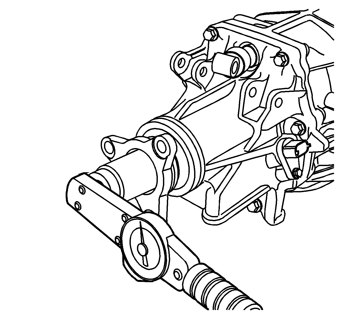
- Measure the rotational torque/drag torque of the output flange by using a suitable tool. Record this initial rotational torque measurement as value A.
- Attach DT-47735 to the output flange.
- Shift the transmission into any gear.
- Tighten the nut.
- Remove the DT-47735 from the output flange.
- Shift the transmission into NEUTRAL.
- Rotate the output flange several times in order to seat the bearings.
- Measure the rotational torque/drag torque of the output flange by using a suitable tool. Record this measurement as value B.
- Subtract value A from value B. Verify that the resulting measurement is within the specified range.
- Repeat the previous steps until you have confirmed that the rotational torque specification is reached then stake the nut in place. If the rotational torque requirement has been exceeded, replace the spacer (191) and repeat steps 2-16.
- Install the output sensor (213) and bolt (215) into the rear extension housing.
- Install a NEW backup lamp washer (208) and switch into the case.
- Install the NEW gaskets (33), drain plug (34) and fill plug (79).
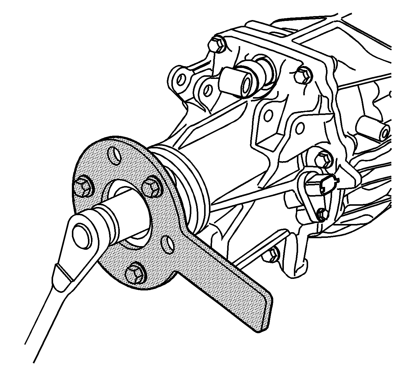

Tighten
Tighten the nut 220-565 N·m (162-417 lb ft).
Specification
The rotational torque specification is .45-1.35 N·m (4-12 lb in).
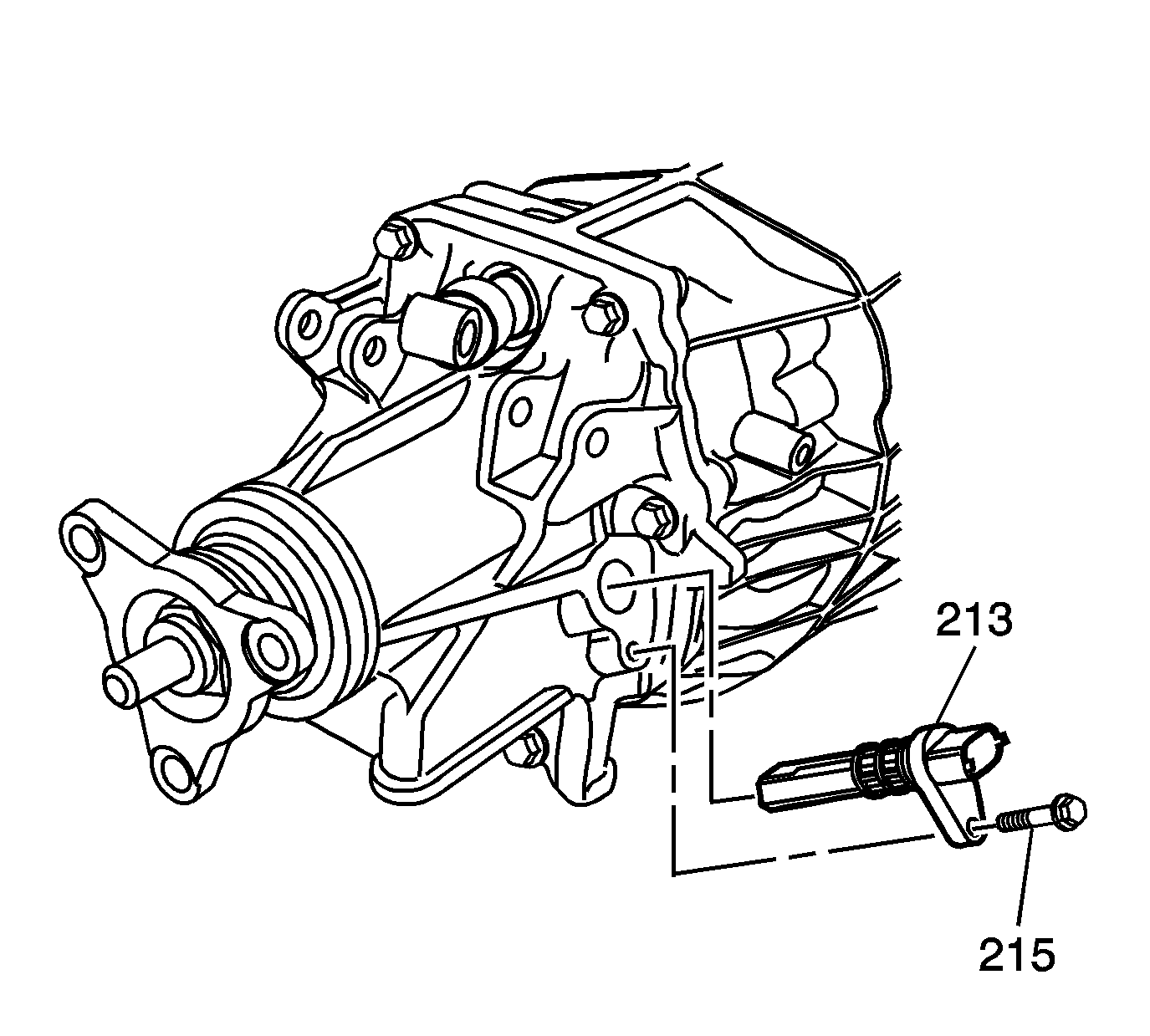
Tighten
Tighten the bolt to 8 N·m (71 lb in).
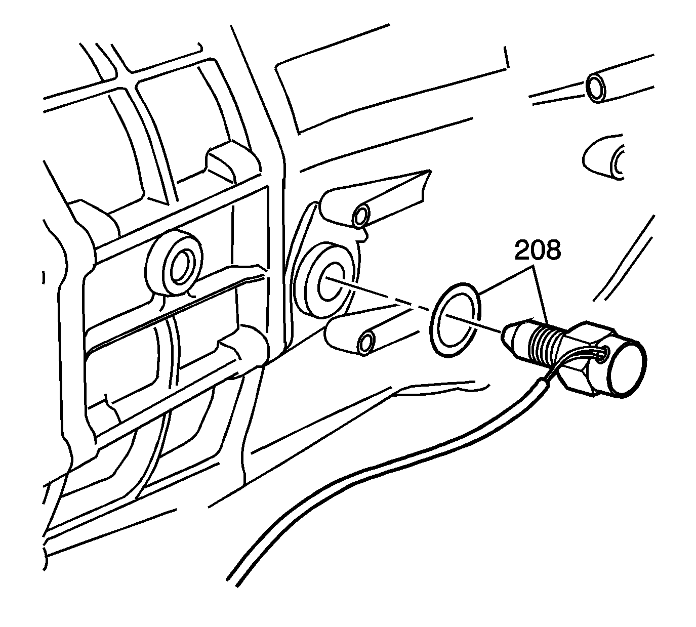
Tighten
Tighten the switch to 44 N·m (32 lb ft).
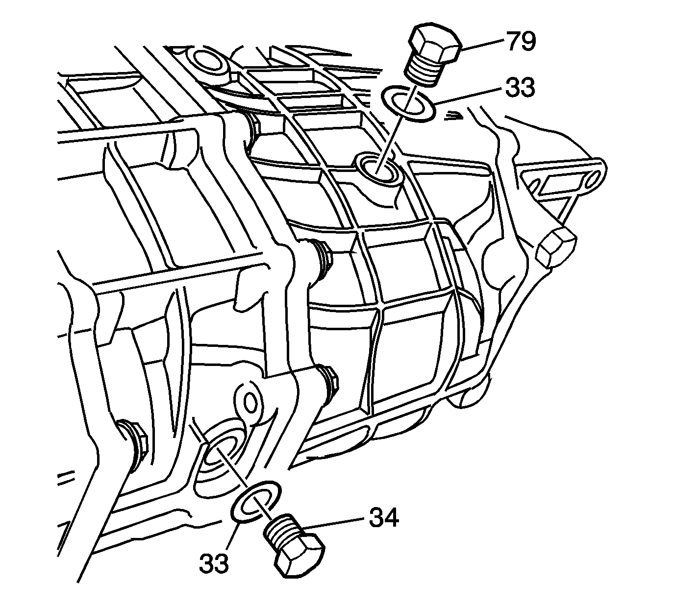
Tighten
Tighten both plugs to 37 N·m (27 lb ft).
