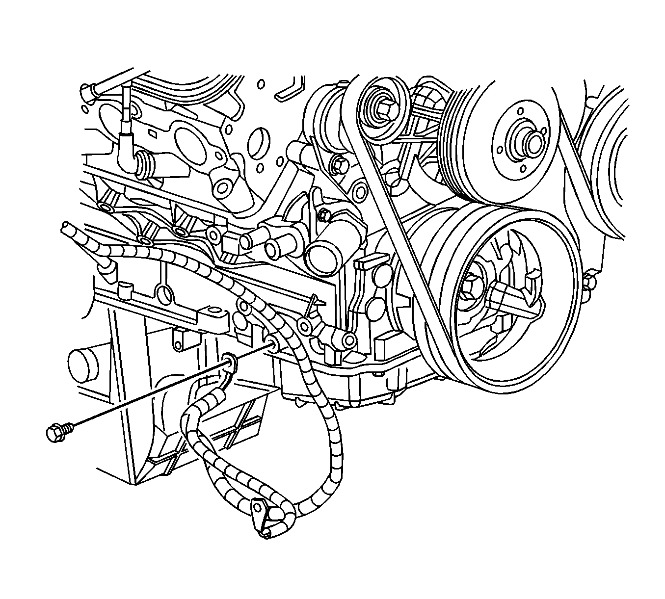
- Install the
J 42451-1
to the engine.
Tighten
Tighten the M10 engine lift bracket bolts to 50 N·m (37 lb ft).
- Install an engine hoist to the
J 42451-1
.
- Remove the engine from the engine stand.
- Install the engine to the vehicle.
- Align the engine and transmission.
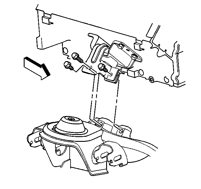
- Install the left and right engine mount-to-engine mount bracket bolts.
Tighten
Tighten the engine mount-to-engine mount bracket bolts to 60 N·m (44 lb ft).
- Install the upper transmission bolts until snug.
- Remove the floor jack from under the transmission.
- Remove the engine hoist.
- Remove the
J 42451-1
from the engine.
- Install the left and right exhaust manifolds. Refer to
Exhaust Manifold Installation - Left Side
and to
Exhaust Manifold Installation - Right Side
.
- Install the intake manifold. Refer to
Intake Manifold Installation
.
- Install the ignition coil(s) and the spark plug wire(s). Refer to
Ignition Coil Replacement
.
- Raise the vehicle.
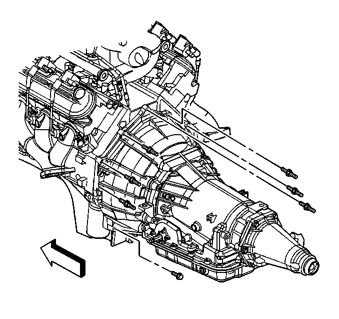
- Remove the
J 21366
from the transmission.
- Install the automatic transmission bolt/studs, if equipped.
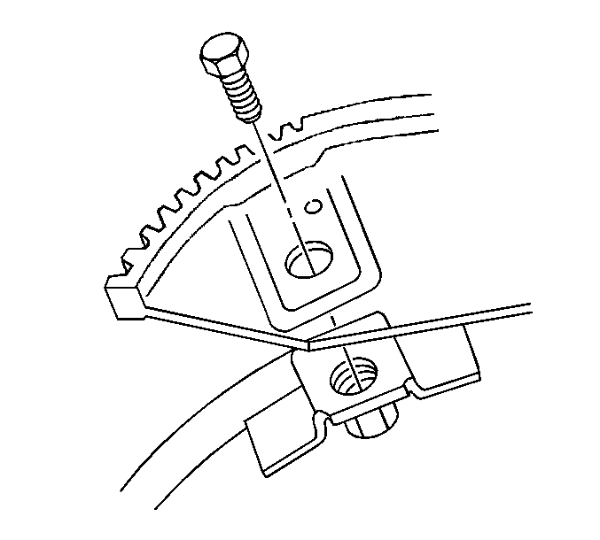
- Install the torque converter bolts, if equipped.
Tighten
| • | If equipped with the 4L60-E, tighten the torque converter bolts to 63 N·m (46 lb ft). |
| • | If equipped with the 4L80-E, tighten the torque converter bolts to 60 N·m (44 lb ft). |
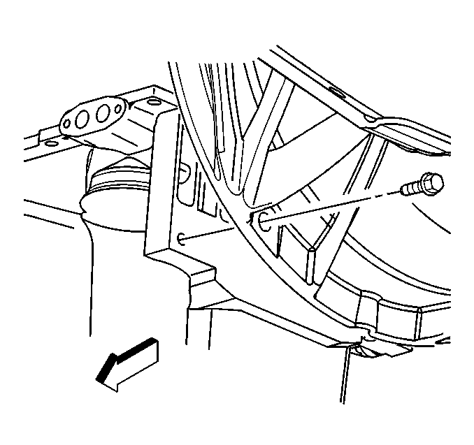
- If equipped with the 4L80-E automatic transmission, install the transmission converter cover bolts.
Tighten
Tighten the transmission converter cover bolts to 33 N·m (24 lb ft).
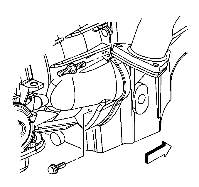
- If equipped with the 4L60-E automatic transmission, install the transmission bolt and stud on the right side.
Tighten
Tighten the automatic transmission bolts/studs to 50 N·m (37 lb ft).
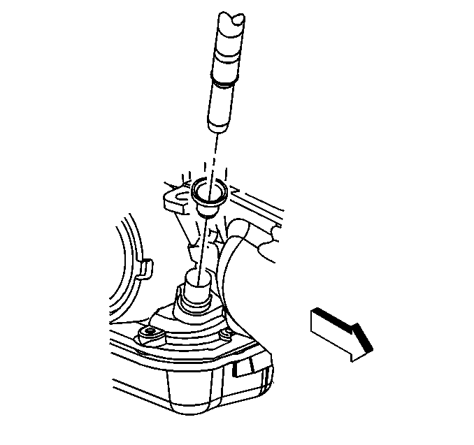
- Install the automatic transmission oil level indicator tube, if equipped.
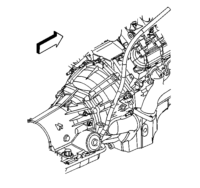
- Install the automatic transmission oil level indicator tube nut, if equipped.
Tighten
Tighten the automatic transmission oil level indicator tube nut to 18 N·m (13 lb ft).
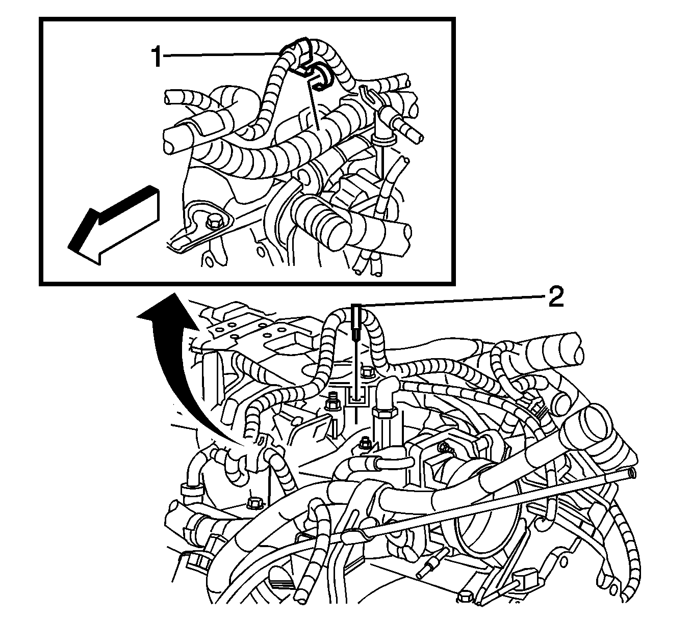
- Install the positive battery cable clip (1).
- Install the catalytic converter. Refer to
Catalytic Converter Replacement
.
- Connect the following electrical connectors:
| • | Crankshaft position sensor |
| • | Engine oil level sensor |
| • | Coolant heater, if equipped |
- Install the starter motor. Refer to
Starter Motor Replacement
.
- Lower the vehicle.
- Position the generator bracket assembly to the front of the engine.
- Install the generator bracket assembly. Refer to
Generator Bracket Replacement
.
- Install the heater hoses to the water pump.
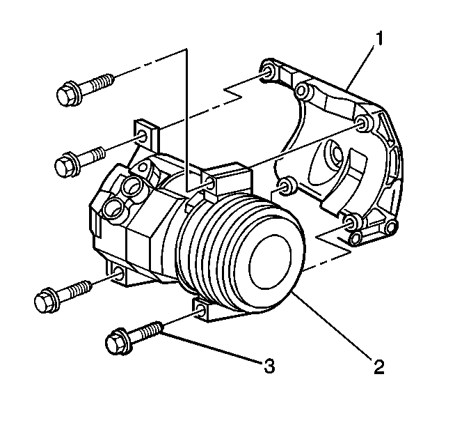
- Install the air conditioning compressor (2) to the engine.
Tighten
Tighten the compressor mounting bolts to 68 N·m (50 lb ft).
- Install the air conditioning discharge hose to the compressor.
Tighten
Tighten the bolt to 35 N·m (26 lb ft).
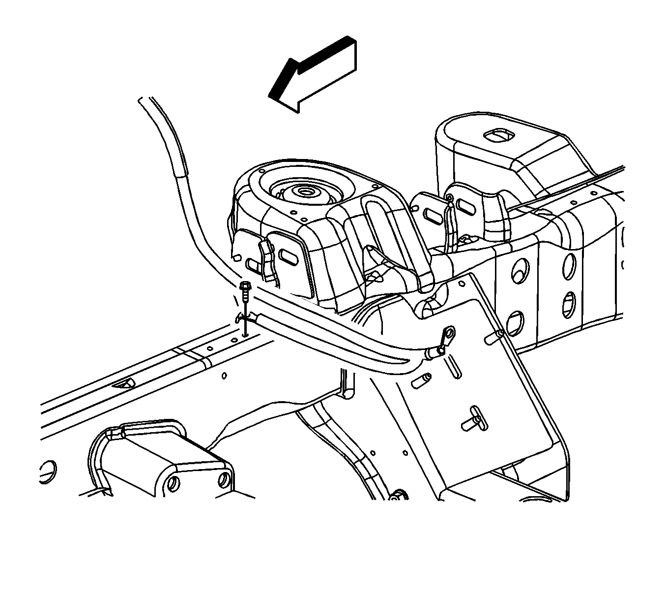
- Install the engine ground strap to the frame.
Tighten
Tighten the bolt to 25 N·m (18 lb ft).
- Install the ground strap and negative battery cable to the engine.
Tighten
Tighten the nut to 25 N·m (18 lb ft).
- Install the clutch fan. Refer to
Fan Clutch Replacement
.
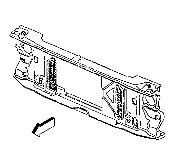
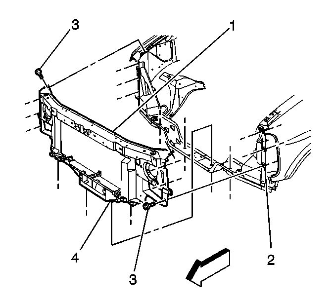
- With the aid of an assistant, position the core support assembly to the vehicle.
- Install the core support bolts.
Tighten
| • | Tighten the core support bolts to 25 N·m (18 lb ft). |
| • | Tighten the core support nuts to 57 N·m (42 lb ft). |
- Install the positive battery cable to the underhood fuse panel.
Tighten
Tighten the bolt to 12 N·m (106 lb in).
- Install the G106 to the inner fender. Refer to
Ground Distribution Schematics
.
Tighten
Tighten the bolt to 10 N·m (89 lb in).
- Connect the C4 to the underhood fuse panel. Refer to
Power Distribution Schematics
.
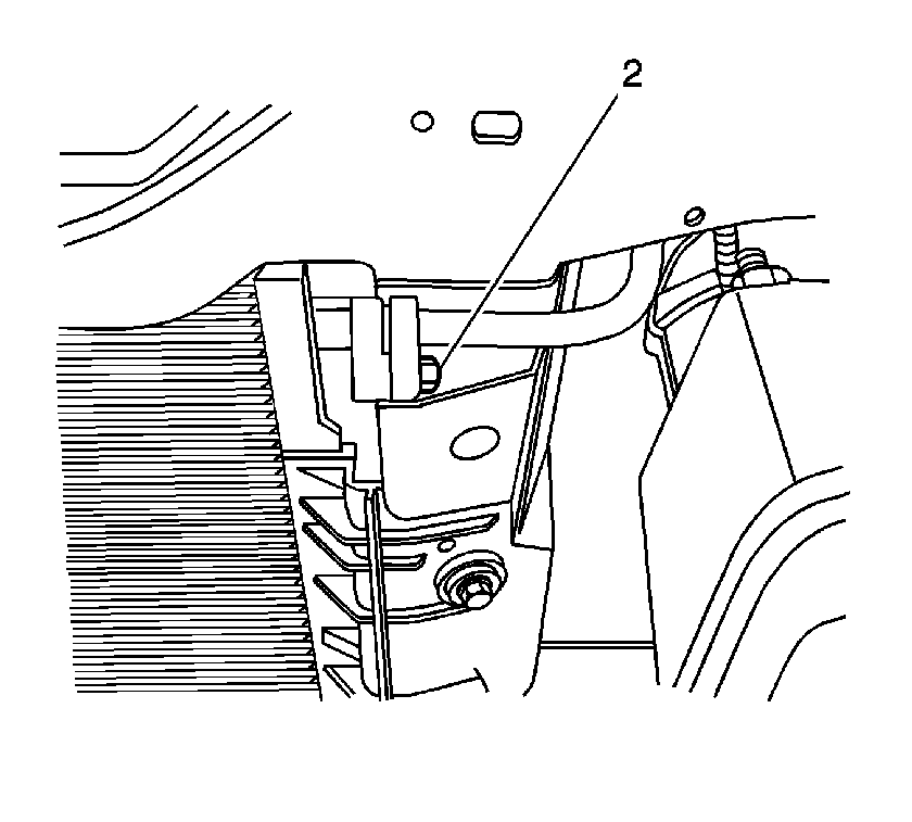
- Install the air conditioning lines (2) to the condenser.
Tighten
Tighten the remaining nuts to 16 N·m (12 lb ft).
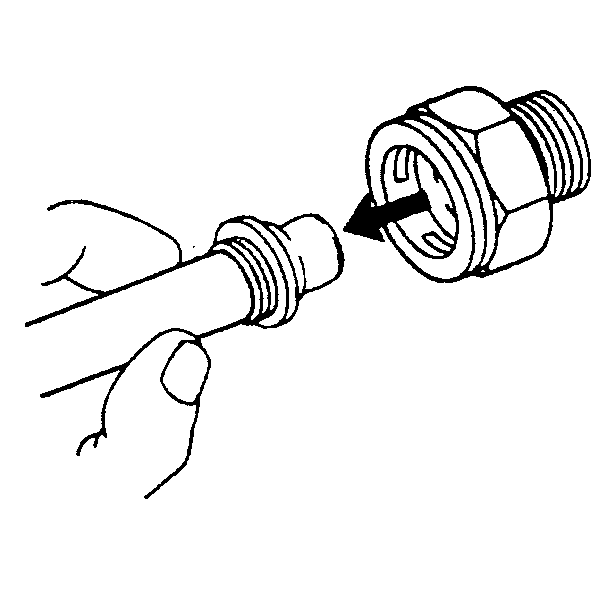
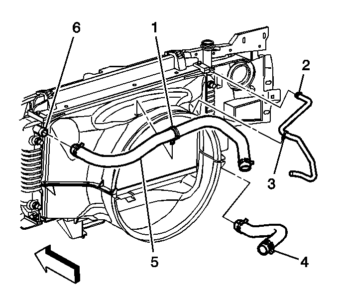
- Install the transmission cooler lines to the radiator.
- Install the oil cooler lines to the radiator, if equipped.
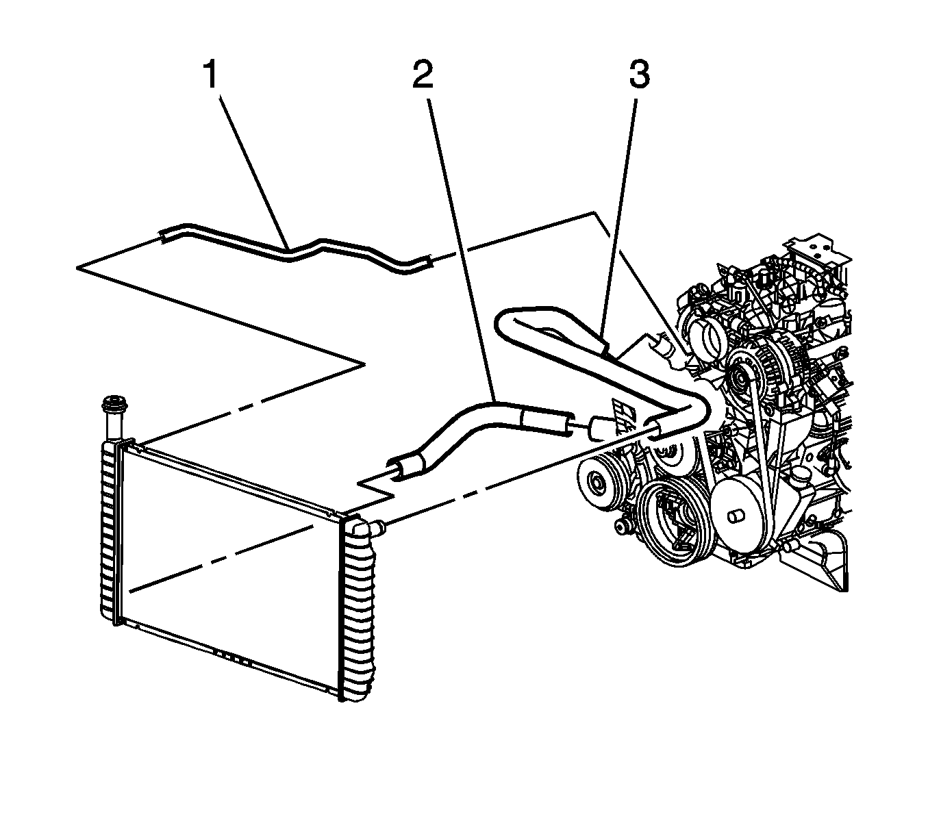
- Install the radiator hoses to the thermostat housing and water pump.
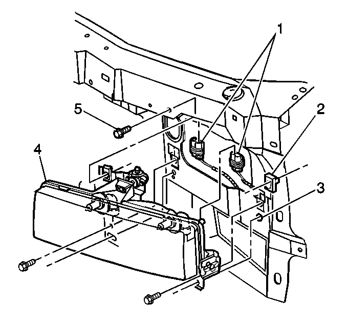
- Install the headlamp capsules (4). Refer to
Headlamp Capsule Replacement
.
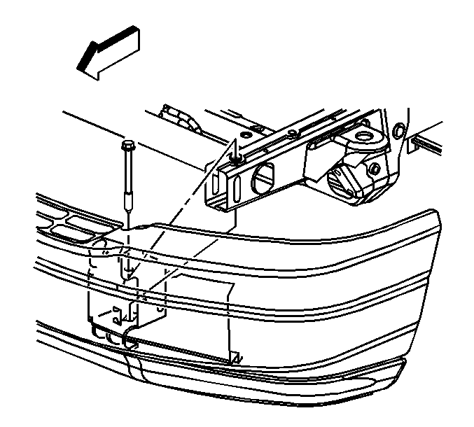
- Install the front bumper. Refer to
Front Bumper Replacement
.
- Install the air cleaner assembly. Refer to
Air Cleaner Assembly Replacement
.
- Install the coolant reservoir. Refer to
Coolant Recovery Reservoir Replacement
.
- Install the sheet metal to the fender supports.
Tighten
Tighten the bolts to 25 N·m (18 lb ft).
- Fill the cooling system with coolant. Refer to
Cooling System Draining and Filling
.
- Fill the crankcase with the proper quantity and grade of engine oil. Refer to
Approximate Fluid Capacities
or
Fluid and Lubricant Recommendations
.
- Perform the CKP system variation learn procedure. Refer to
Crankshaft Position System Variation Learn
.
Important: After an overhaul, the engine should be tested. Use the following procedure after the engine is installed in the vehicle.
| 51.1. | Disable the ignition system. |
| 51.2. | Crank the engine several times. Listen for any unusual noises or evidence that parts are binding. |
| 51.3. | Enable the ignition system. |
| 51.4. | Start the engine and listen for unusual noises. |
| 51.5. | Check the vehicle oil pressure gage or light and confirm that the engine has acceptable oil pressure. |
| 51.6. | Run the engine speed at about 1,000 RPM until the engine has reached normal operating temperature. |
| 51.7. | Listen for sticking lifter and other unusual noises. |
| 51.8. | Inspect for fuel, oil and/or coolant leaks while the engine is running. |
| 51.9. | Perform a final inspection for the proper engine oil and coolant levels. |
- Close the hood.
