For 1990-2009 cars only
Special Tools
| • | J 24319-B Steering Linkage and Tie Rod Puller |
| • | J 43631 Ball Joint Remover |
| • | J 34028 Inner Tie Rod Wrench |
Removal Procedure
- Raise and suitable support the vehicle. Refer to Lifting and Jacking the Vehicle.
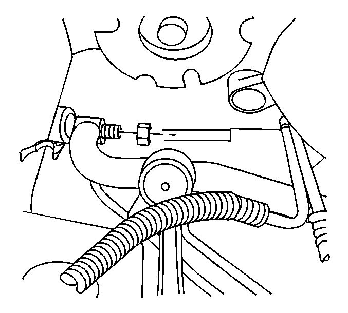
- Loosen the inner tie rods to relay rod retaining nuts using J 34028 .
- Remove the inner tie rods to the relay rod retaining nuts.
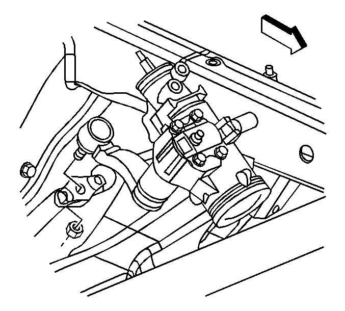
- Rotate the steering linkage to remove the inner tie rods from the relay rod.
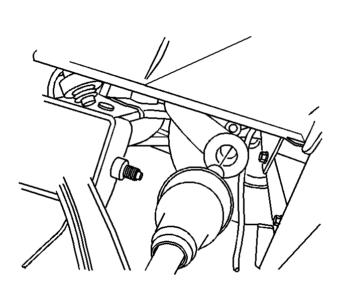
- Remove the idler arm to relay rod retaining nut. Discard the nut.
- Remove the pitman arm retaining nut. Discard the nut.
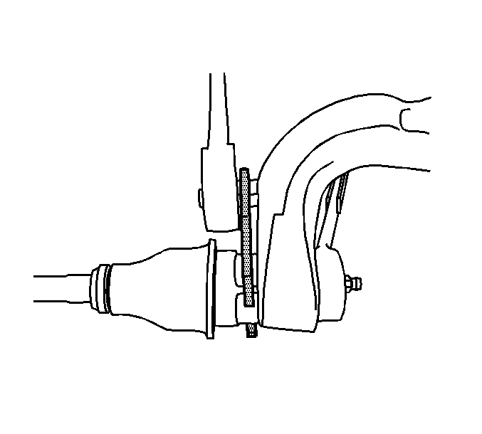
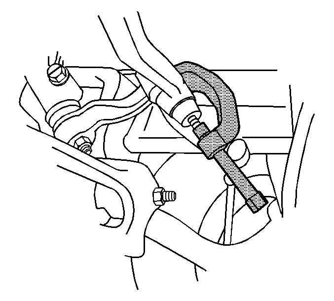
- Disconnect the relay rod from the idler arm using the J 43631 .
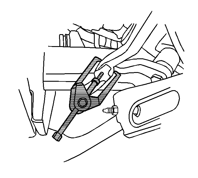
- Disconnect the relay rod from the pitman arm using the J 24319-B .
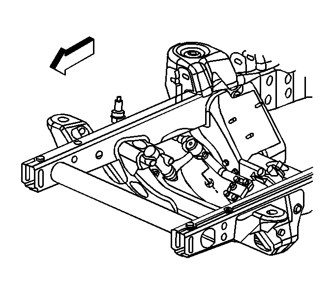
- Remove the relay rod from the vehicle.
Installation Procedure
- Install the relay rod to the vehicle.
- Install the relay rod to the pitman arm and idler arm.
- Install the new relay rod to the idler arm retaining nut and tighten to 63 N·m (47 lb ft).
- Install the new relay rod to the pitman arm retaining nut and tighten to 63 N·m (47 lb ft).
- Install the inner tie rods to the relay rod.
- Install the inner tie rods to relay rod retaining nuts.
- Tighten the inner tie rods to relay rod retaining nuts using J 34028 to 112 N·m (83 lb ft).
- Lower the vehicle.
- Verify the wheel alignment. Refer to Wheel Alignment Measurement.

Caution: Refer to Fastener Caution in the Preface section.


