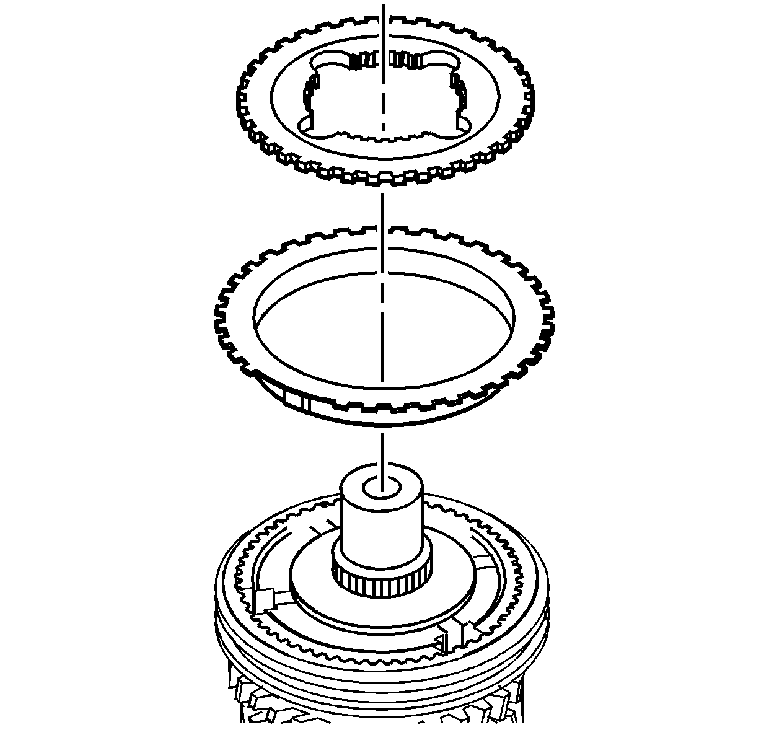
Important: For installation alignment scribe an alignment mark on the synchronizer
hubs and synchronizer sleeves before removing. To prevent the synchronizer
springs and struts from being lost, do not separate the synchronizer
hubs from the synchronizer sleeves. Keep the synchronizer clutch
gear and the blocking rings with the synchronizer hubs. Organize
the components in order to install the components in their original
location and position.
- Position the mainshaft assembly in a soft jaw vise for ease of disassembly.
- Remove the 4th speed gear clutch gear.
- Remove the 4th speed gear synchronizer ring.
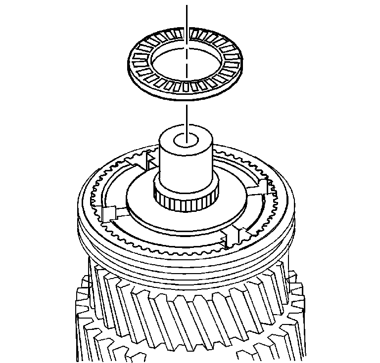
- Remove the main drive
gear thrust bearing.
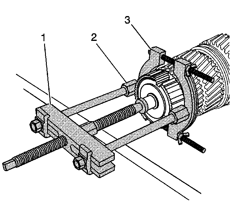
- Using the J 44707
(1), the J 44759
(2), and the J 36513
(3), remove the 3rd/4th synchronizer
hub from the mainshaft with the 3rd speed gear.
| • | Position the J 36513
(3) behind 3rd gear. |
| • | A hydraulic press with a large bearing splitter can also be used. |
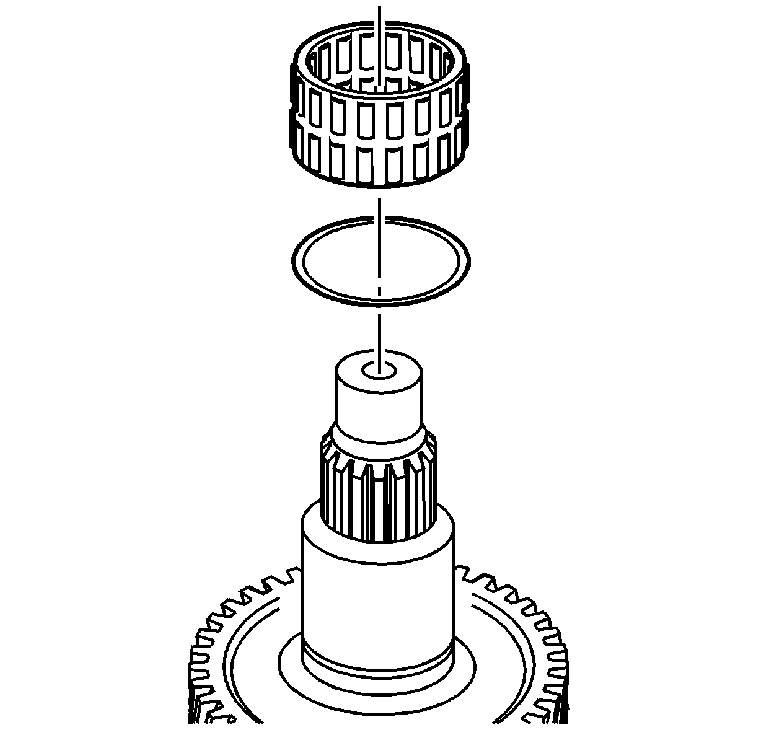
- Remove the 3rd speed gear
bearing.
- Remove the mainshaft bearing spacer.
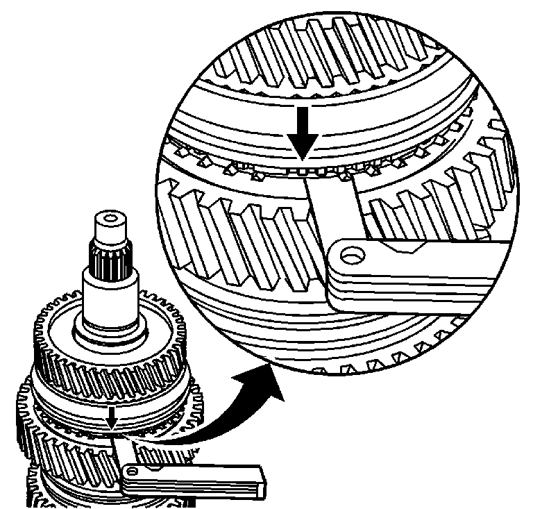
Important: The wear of the 1st and 2nd speed synchronizer can only be measured
correctly while the synchronizer and the speed gears are installed on the
mainshaft. The synchronizer uses a fixed inner cone.
- In order to measure the wear gap for the 1st speed gear position, perform
the following:
| 8.1. | Engage the 1st/2nd synchronizer sleeve in the 2nd speed gear position. |
| 8.2. | Move the sleeve, with light, even, pressure towards 1st gear.
The inserts will press against the blocker ring. |
| 8.3. | Insert the feeler gage between the synchronizer hub and the blocker
ring to measure the wear gap. |
The 1st speed synchronizer wear
gap is 1.37-0.31 mm (0.054-0.012 in).
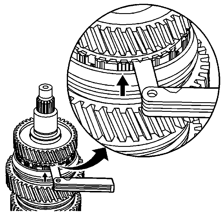
- In order to measure the
wear gap for the 2nd gear position, perform the following:
| 9.1. | Engage the 1st/2nd synchronizer sleeve in the 1st speed gear position. |
| 9.2. | Move the sleeve, with light, even, pressure towards 2nd gear.
The inserts will press against the blocker ring. |
| 9.3. | Insert the feeler gage between the 2nd gear clutch teeth and the
blocker ring to measure the wear gap. |
The 2nd speed synchronizer
wear gap is 2.16-1.14 mm (0.085-0.045 in).
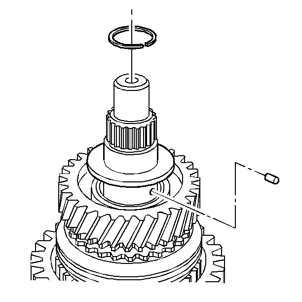
- Remove the 2nd speed gear
thrust washer retainer ring.
- Remove the 2nd speed gear thrust washer.
- Remove the 2nd speed gear thrust washer retaining pin.
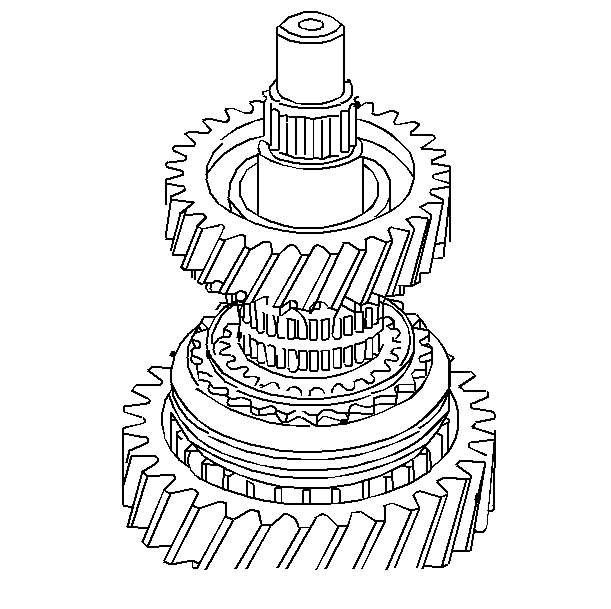
- Remove the 2nd speed gear.
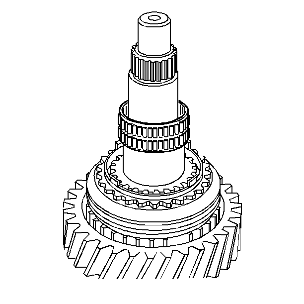
- Remove the 2nd speed gear
bearing.
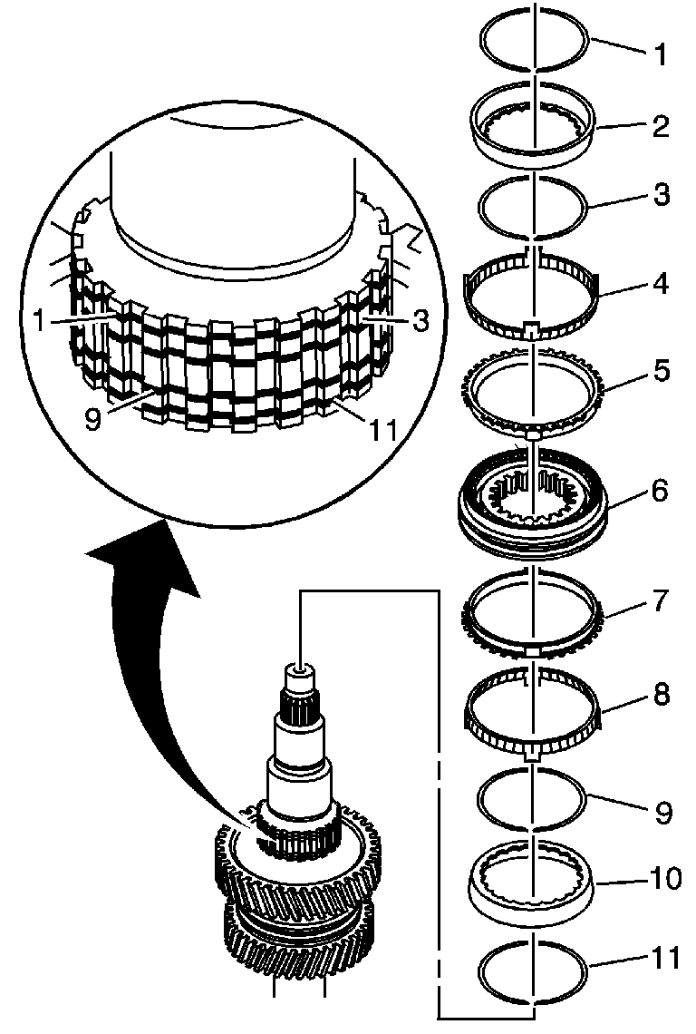
Important: For installation alignment scribe an alignment mark on the synchronizer
hubs and synchronizer sleeves before removing. To prevent the synchronizer
springs and struts from being lost, do not separate the synchronizer
hubs from the synchronizer sleeves. Keep the synchronizer clutch
gear and the blocking rings with the synchronizer hubs. Organize
the components in order to install the components in their original
location and position.
- Remove the following 1st/2nd gear synchronizer components:
| 15.1. | The 2nd speed gear synchronizer outer ring retaining ring front (1) |
| 15.2. | The 2nd speed gear synchronizer inner ring (2) |
| 15.3. | The 2nd speed gear synchronizer center ring (4) |
| 15.4. | The 2nd speed gear synchronizer outer ring (5) |
| 15.5. | The 2nd speed gear synchronizer outer ring retaining ring rear (3) |
| 15.6. | The 1st/2nd speed synchronizer assembly (6) |
| 15.7. | The 1st speed gear synchronizer outer ring (7) |
| 15.8. | The 1st speed gear synchronizer center ring (8) |
| 15.9. | The 1st speed gear outer ring retaining ring front (9) |
| 15.10. | The 1st speed gear synchronizer inner ring (10) |
| 15.11. | The 1st speed gear synchronizer outer ring retaining ring rear (11) |
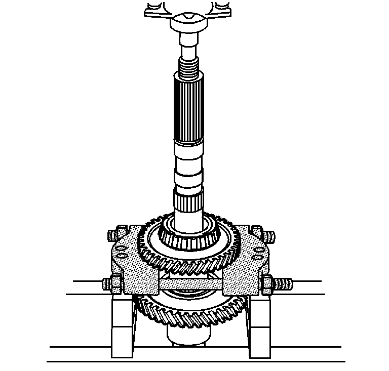
- Using a hydraulic press
and the J 44749
or equivalent,
remove the rear mainshaft bearing. Use the J 44749
under the reverse gear.
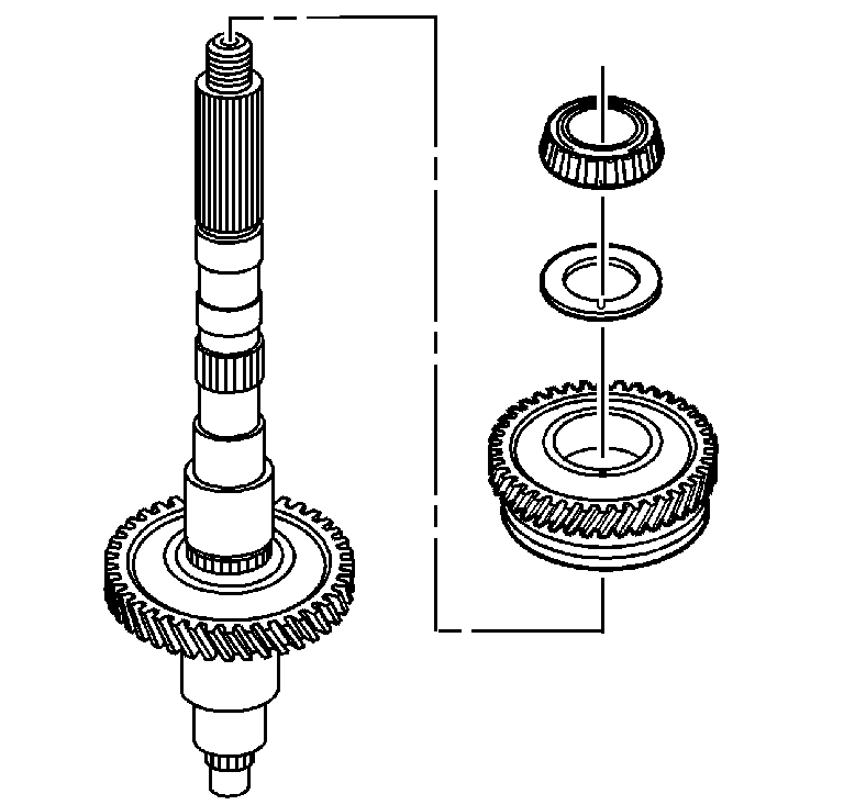
- Remove the rear mainshaft
bearing.
- Remove the reverse gear thrust washer.
- Remove the reverse gear.
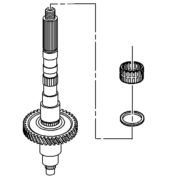
- Remove the reverse gear
bearing.
- Remove the mainshaft gear spacer.
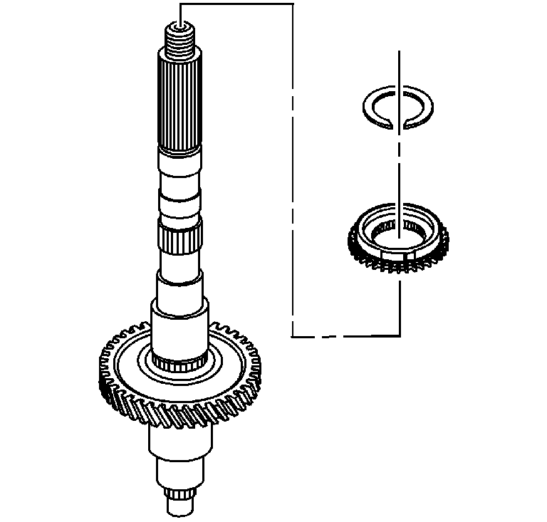
- Remove the retainer ring
for the reverse gear clutch hub.
- Remove the reverse gear clutch hub and the synchronizer ring.
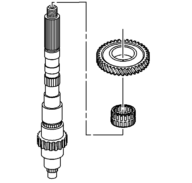
- Remove the 1st speed gear.
- Remove the 1st speed gear bearing.


