For 1990-2009 cars only
Removal Procedure
- Drain the generator control module (GCM) cooling system. Refer to Generator Control Module Cooling System Draining and Filling .
- Raise the hood to the service position, and perform the following steps:
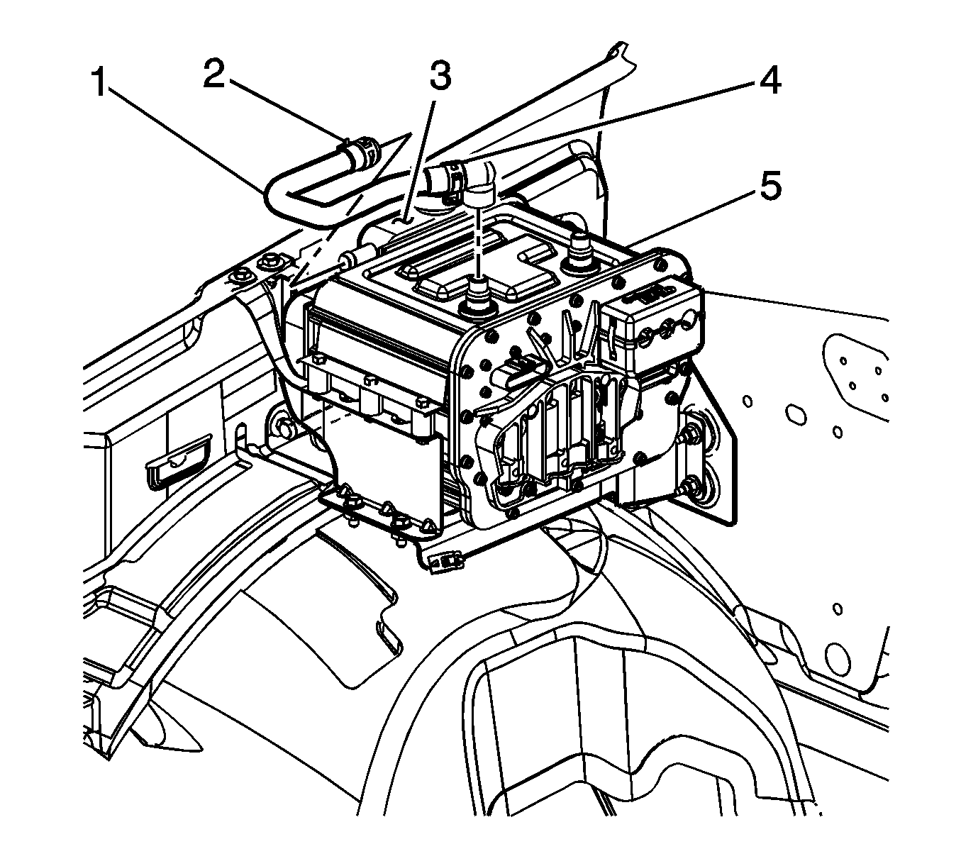
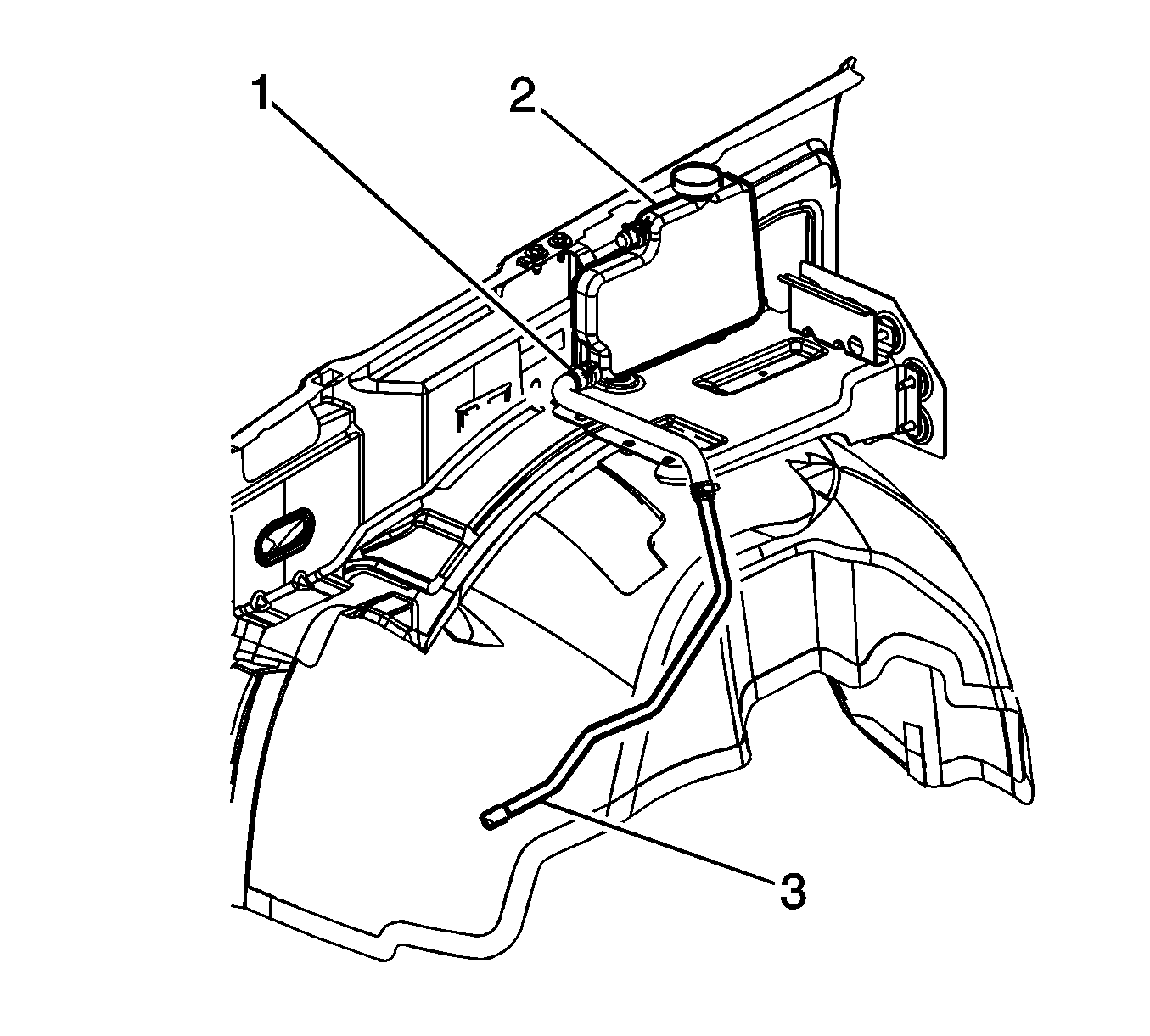
- Reposition the GCM coolant tank hose clamp (2) from the GCM coolant tank (3).
- Remove the GCM coolant tank hose (1) from the GCM coolant tank (3).
- Reposition the GCM pressure relief hose clamp from the GCM pressure relief valve.
- Remove the GCM pressure relief hose from the GCM pressure relief valve.
- Remove the surge tank mounting bolts. Position the surge tank away from the GCM module.
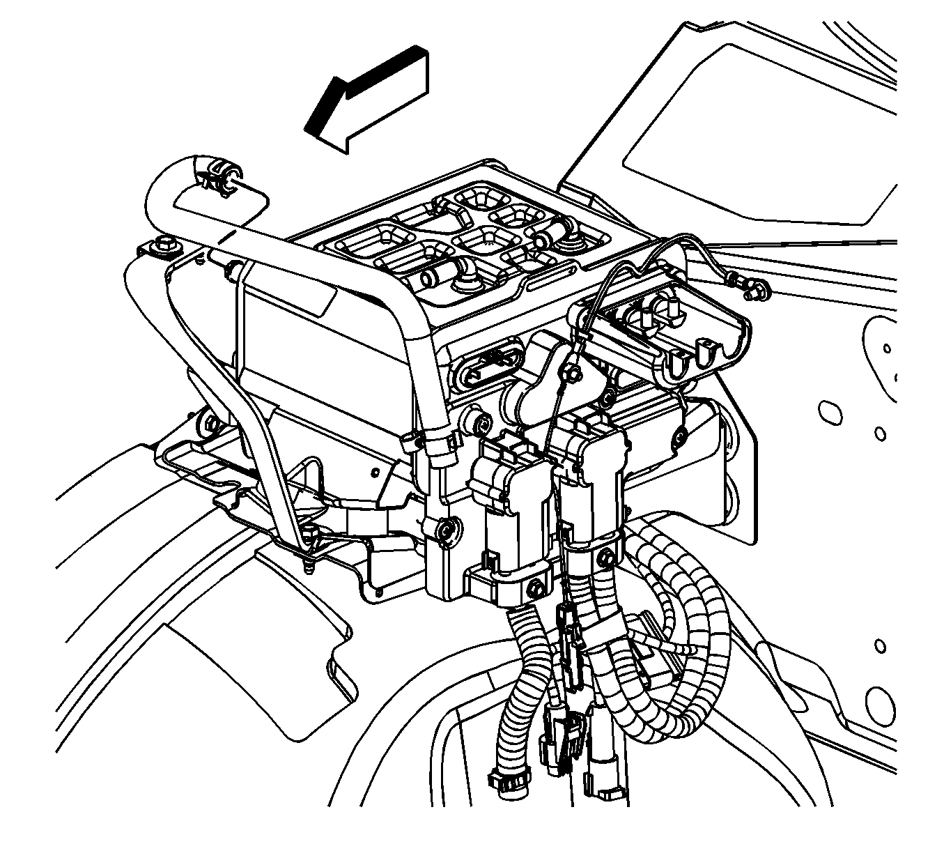
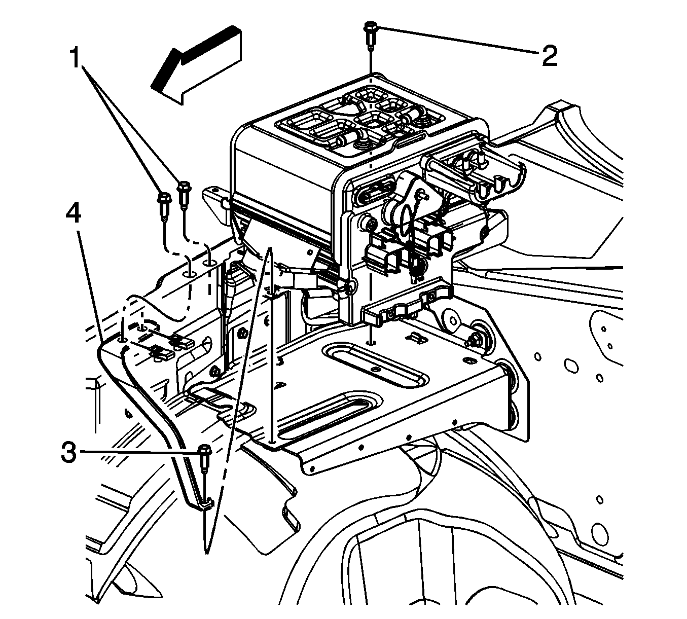
- Remove the bolts (1) from the brace.
- Reposition the GCM coolant pump inlet hose clamp (1) from the GCM coolant tank (2).
- Remove the GCM coolant pump inlet hose (3) from the GCM coolant tank (2).
- Remove the bolts from the GCM coolant tank.
- Reposition the GCM coolant tank in order to access the GCM rear bolt.
- Remove the rear bolt (2) from the GCM.
- Remove the front bolt (3) from the GCM.
- Reposition the GCM in order to remove the GCM coolant tank.
- Remove the GCM coolant tank (2) from the vehicle.
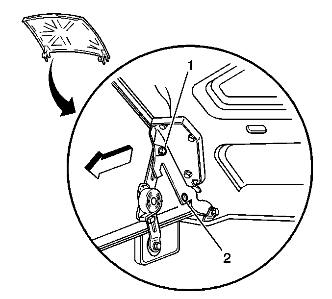
| 2.1. | Remove the ground strap from the hood. |
| 2.2. | Remove the hood hinge bolts (1). |
| 2.3. | Raise the hood until vertical. |
| 2.4. | Install the hood hinge bolts until snug in the service position (2). |


Installation Procedure
- Install the GCM coolant tank (2) to the vehicle.
- Position the GCM coolant tank in order to install the GCM rear bolt.
- Install the rear bolt (2) to the GCM.
- Install the front bolt (3) to the GCM.
- Install the bolts to the GCM coolant tank.
- Install the GCM coolant pump inlet hose (3) to the GCM coolant tank (2).
- Position the GCM coolant pump inlet hose clamp (1) to the GCM coolant tank (2).
- Install the bolts (1) to the brace.
- Install the surge tank.
- Install the GCM pressure relief hose to the GCM pressure relief valve.
- Position the GCM pressure relief hose clamp to the GCM pressure relief valve.
- Install the GCM coolant tank hose (1) to the GCM coolant tank (3).
- Position the GCM coolant tank hose clamp (2) to the GCM coolant tank (3).
- Lower the hood from the service position, perform the following:
- Install the ground strap to the hood.
- Fill the GCM cooling system. Refer to Generator Control Module Cooling System Draining and Filling .


Notice: Refer to Fastener Notice in the Preface section.
Tighten
Tighten the bolt to 20 N·m (15 lb ft).
Tighten
Tighten the bolt to 20 N·m (15 lb ft).
Tighten
Tighten the bolts to 9 N·m (80 lb in).


Tighten
Tighten the bolts to 25 N·m (18 lb ft).


| 14.1. | Remove the hood hinge bolts from the service position (2). |
| 14.2. | Lower the hood to the normal position. |
| 14.3. | Install the hood hinge bolts (1). |
Tighten
Tighten the bolt to 25 N·m (18 lb ft).
Notice: The procedure below must be followed. Improper coolant level could result in a low or high coolant level condition, causing starter/generator control module damage.
