GM Service Manual Online
For 1990-2009 cars only
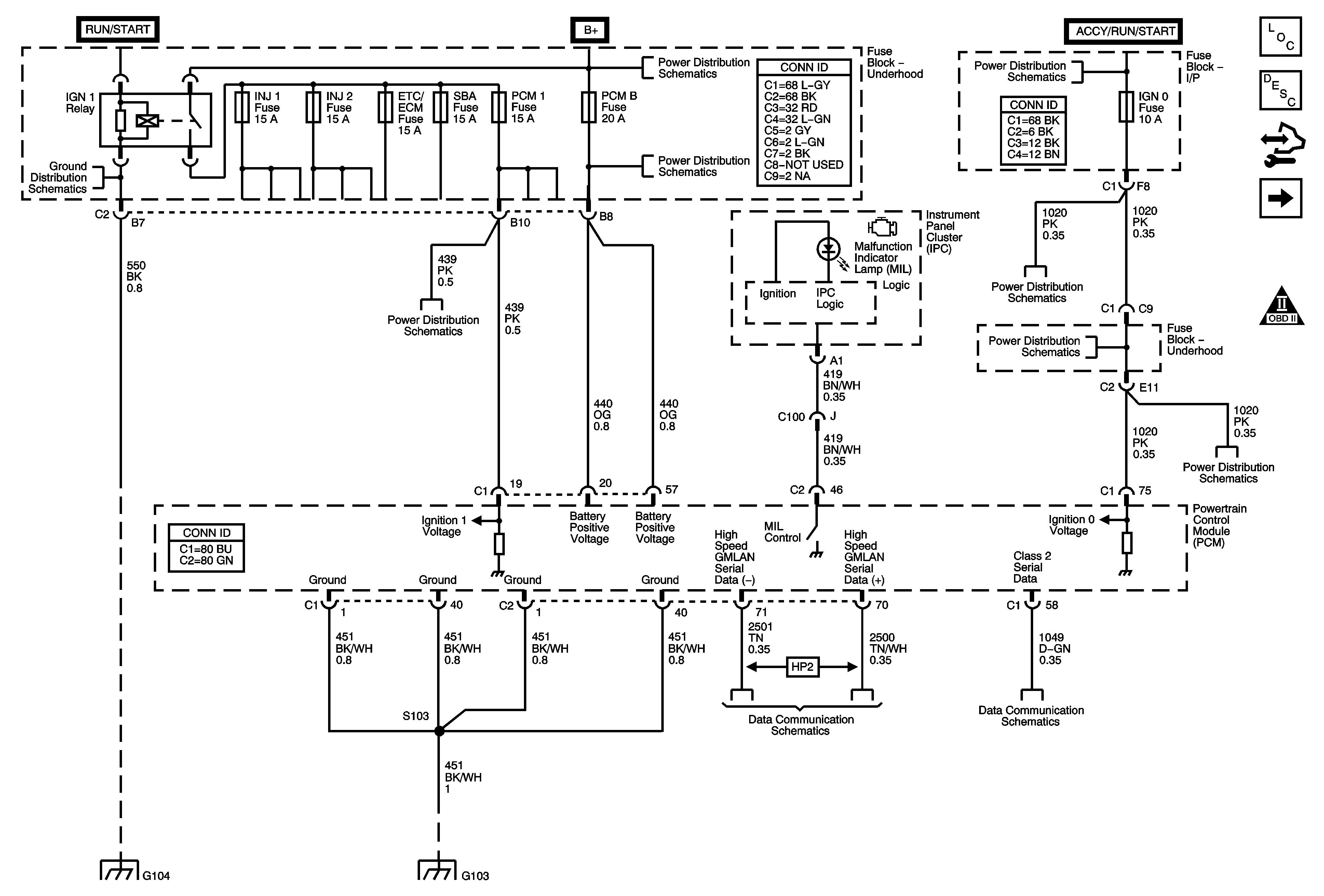
Figure 1:

Module Power, Ground, Serial Data, and MIL

Object Number: 1776279  Size: FS
Master Electrical Component List
Powertrain Control Module Description
Control Module References
Engine Data Sensors - 5-Volt and Low Reference
Engine Controls Schematic Icons
G104, G107, and G110
ETC/ECM, INJ1, INJ2, PCM 1, and SBA Fuses - Gas
B+ Bus Bar
AUX PWR, AUX PWR 2, DDM, ECC/TCM, ECM B, LBEC 2, LCKS, PCM B, PDM, and TCM B Fuses
Ignition Switch - START, RUN, and ACC/RUN/START BUS BARS, IGN A, and CRNK Fuses
IGN 0, RR WPR, SEO ACCY, TBC ACCY, TBC IGN 0, and WS WPR Fuses
G104, G107, and G110
G103 and G106 - Gas
High Speed GM LAN (HP2)
Power, Ground, DLC and Splice Pack SP205
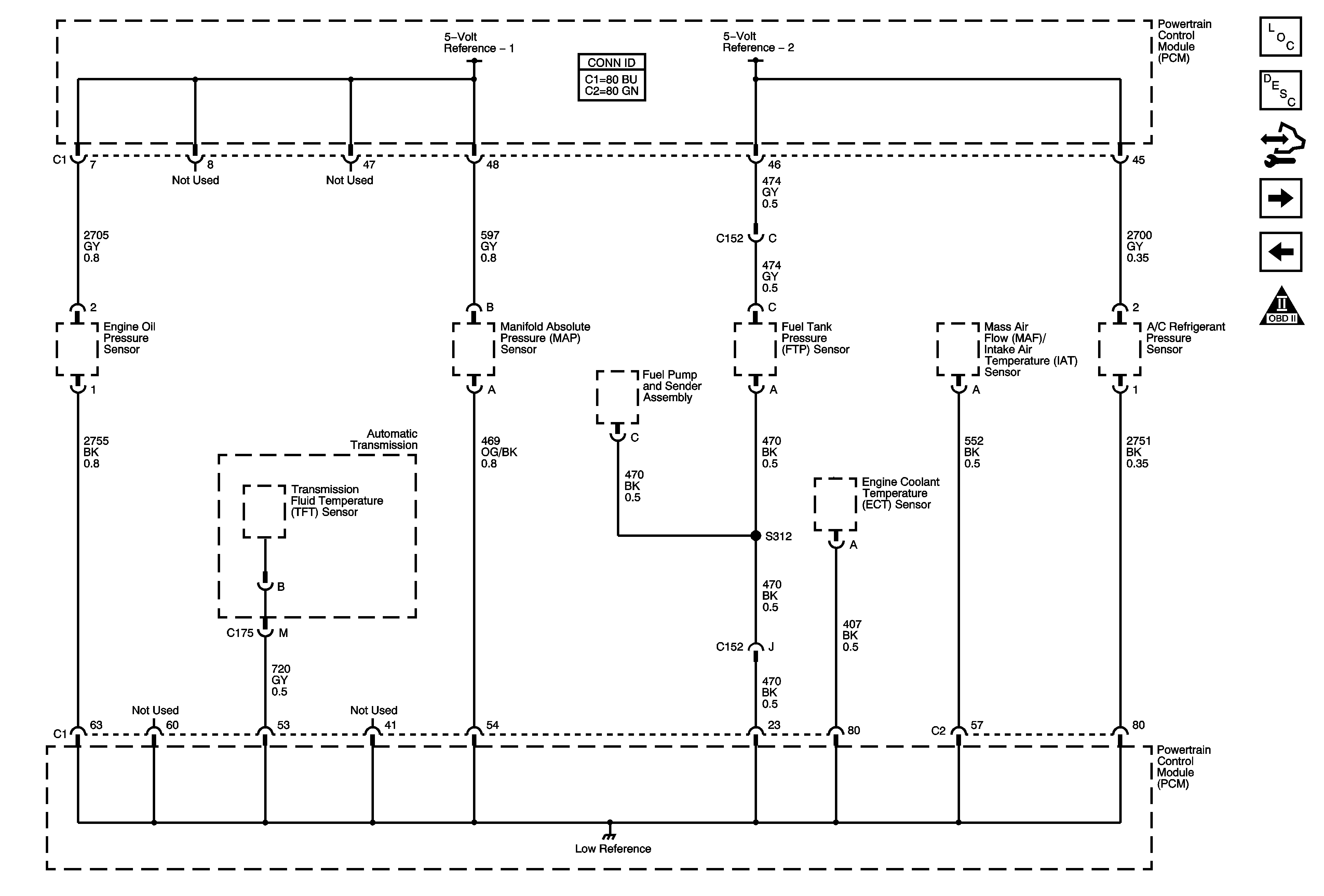
Figure 2:

Engine Data Sensors - 5-Volt and Low References

Object Number: 1776351  Size: FS
Master Electrical Component List
Powertrain Control Module Description
Control Module References
Engine Data Sensors - Pressure, Temperature, MAF, and VSS
Module Power, Ground, Serial Data, and MIL
Engine Controls Schematic Icons
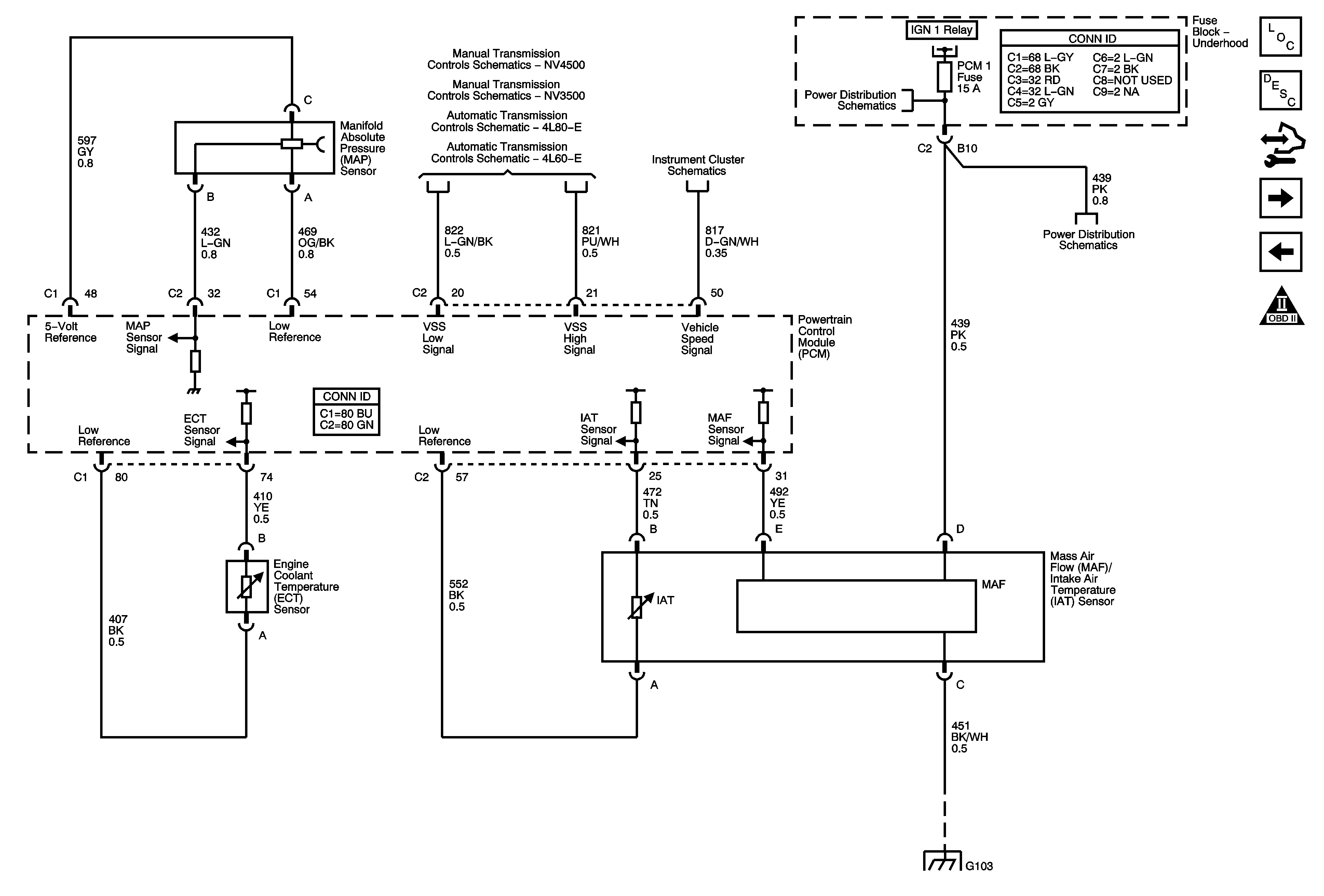
Figure 3:

Engine Data Sensors - Pressure, Temperature, MAF, and VSS


Object Number: 1776355  Size: FS
Master Electrical Component List
Electronic Ignition (EI) System Description
Control Module References
Engine Data Sensors - Oxygen Sensors (w/o HP2)
Engine Data Sensors - 5-Volt and Low Reference
Engine Controls Schematic Icons
Manual Transmission NV4500 Schematics
Manual Transmission NV3500 Schematics
Pressure Controls, Temperature, and VSS
Gages, Vehicle Speed Sensor, Engine Oil Pressure, and Fuel Level Sensors
ETC/ECM, INJ1, INJ2, PCM 1, and SBA Fuses - Gas
G103 and G106 - Gas
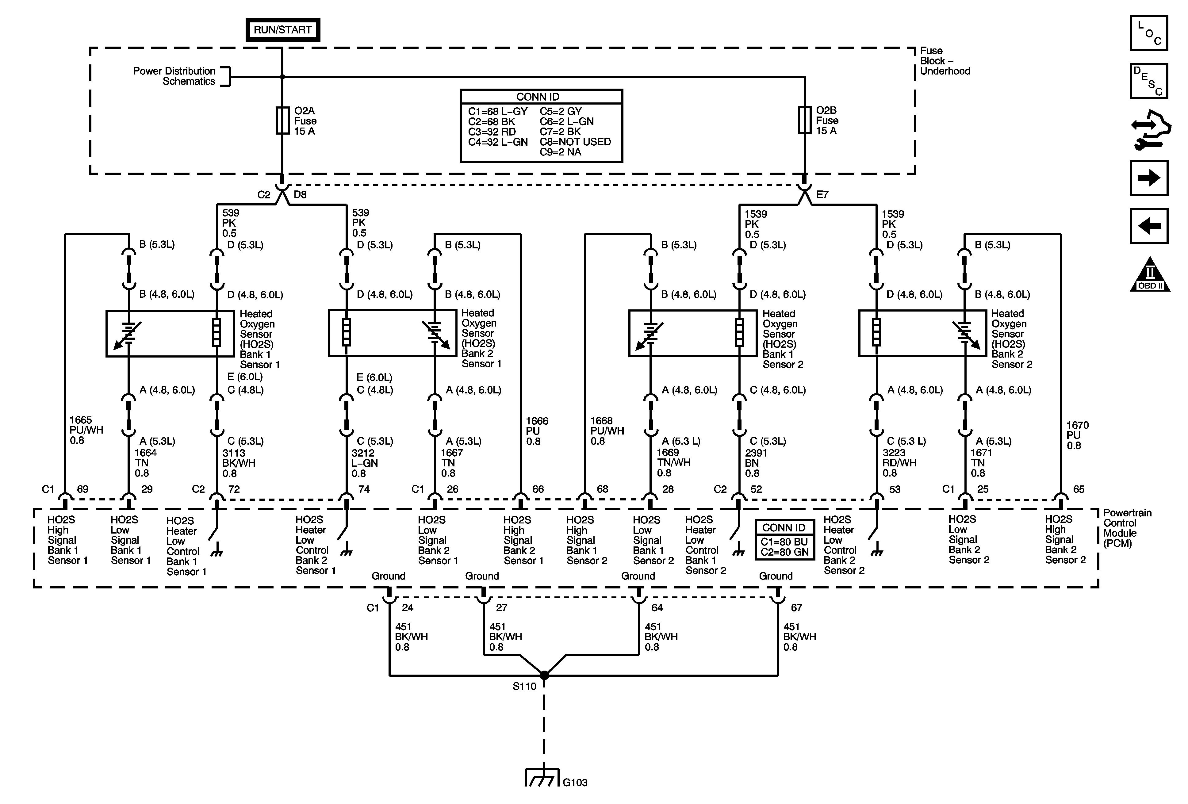
Figure 4:

Engine Data Sensors - Oxygen Sensors (w/o HP2)


Object Number: 1776383  Size: FS
Master Electrical Component List
Fuel System Description (Pickup and Utility)
Control Module References
Engine Data Sensors - Oxygen Sensors (HP2) - 1 of 2
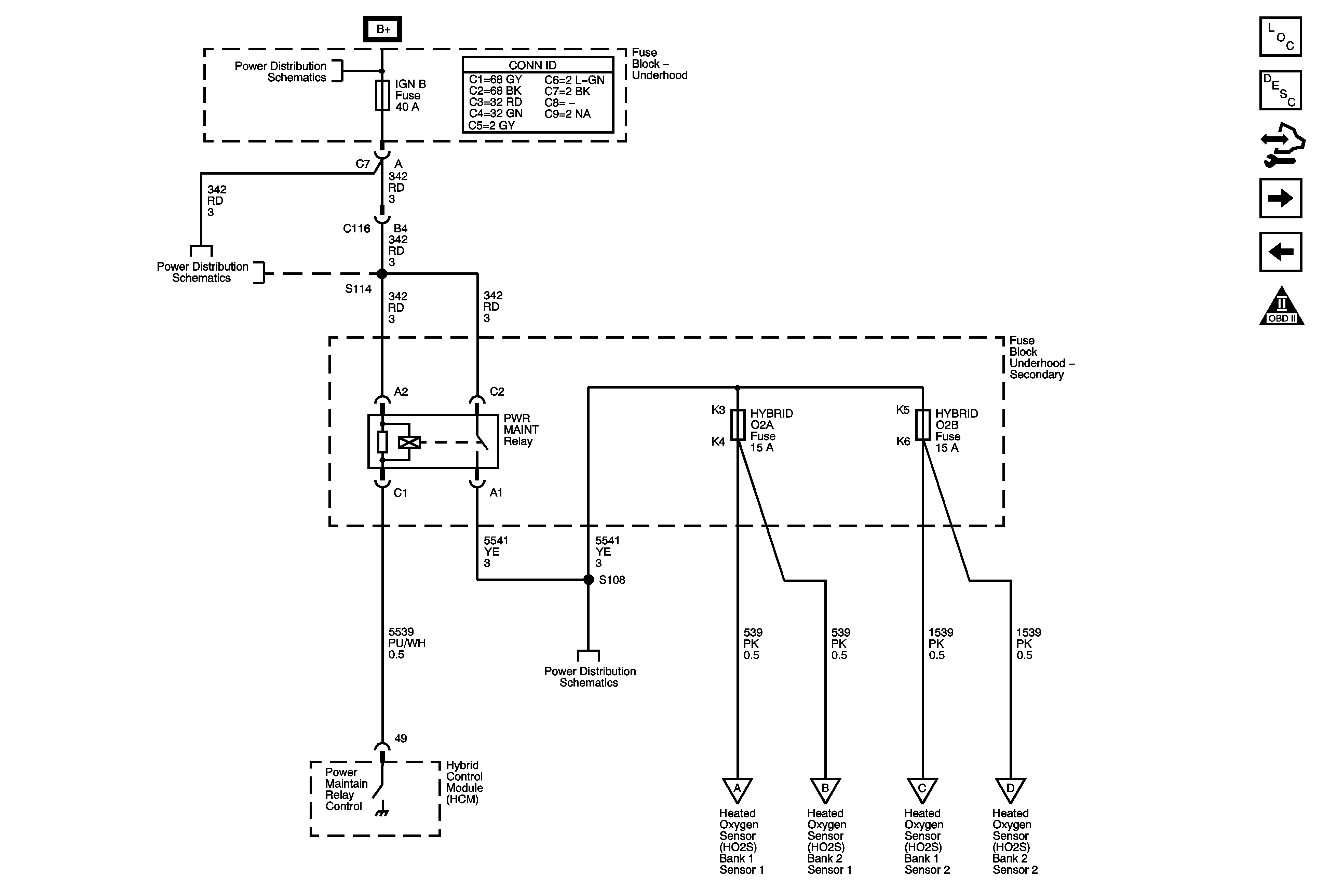
Engine Data Sensors - Pressure, Temperature, MAF, and VSS
Engine Controls Schematic Icons
Ignition Switch - ACC/RUN and RUN/START BUS BARS and IGN B Fuse
G103 and G106 - Gas
Figure 5:

Engine Data Sensors - Oxygen Sensors (HP2) - 1 of 2


Object Number: 1776386  Size: FS
Master Electrical Component List
Fuel System Description (Pickup and Utility)
Control Module References
Engine Data Sensors - Oxygen Sensors (HP2) - 2 of 2
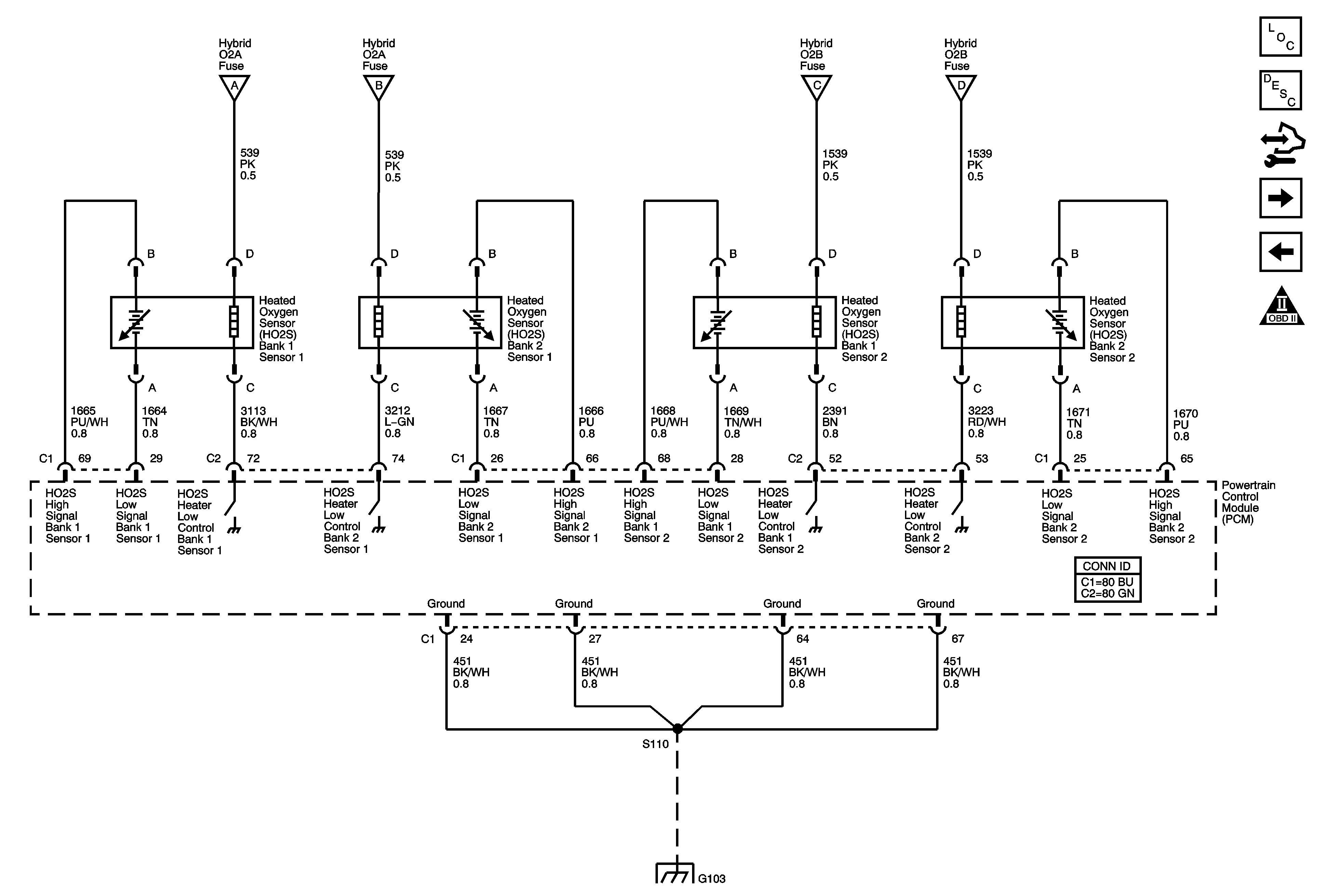
Engine Data Sensors - Oxygen Sensors (w/o HP2)
Engine Controls Schematic Icons
B+ Bus Bar
Ignition Switch - ACC/RUN and RUN/START BUS BARS and IGN B Fuse
COOL PUMP, HYBRID O2A, HYBRID O2B, IGN B, and PWR MAINT Fuses
Engine Data Sensors - Oxygen Sensors (HP2) - 2 of 2
Figure 6:

Engine Data Sensors - Oxygen Sensors (HP2) - 2 of 2


Object Number: 1776628  Size: FS
Master Electrical Component List
Fuel System Description (Pickup and Utility)
Control Module References
Engine Data Sensors - Electronic Throttle Control
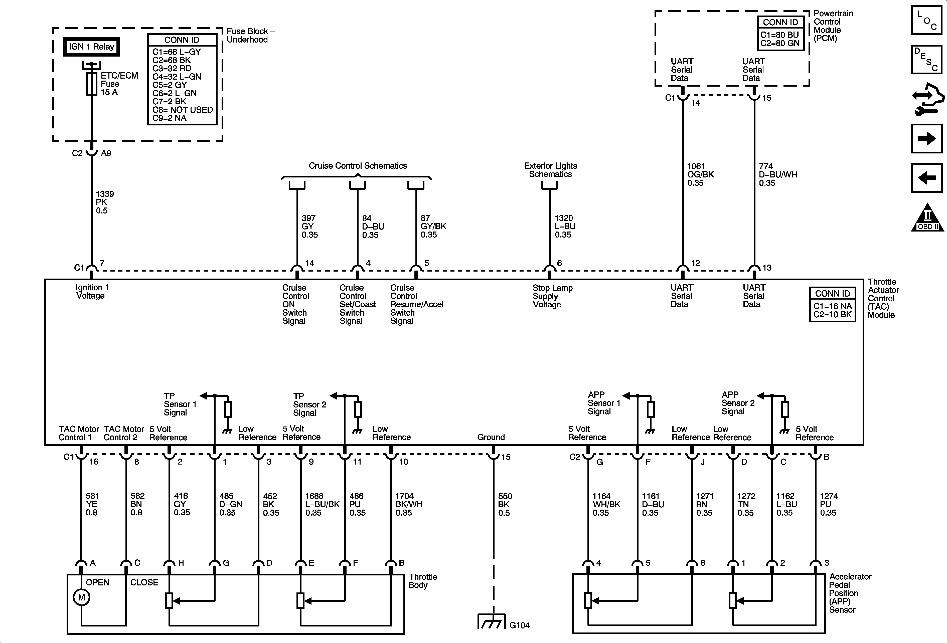
Engine Data Sensors - Oxygen Sensors (HP2) - 1 of 2
Engine Controls Schematic Icons
Engine Data Sensors - Oxygen Sensors (HP2) - 1 of 2
G103 and G106 - Gas
Figure 7:

Engine Data Sensors - Electronic Throttle Control


Object Number: 1776734  Size: FS
Master Electrical Component List
Throttle Actuator Control (TAC) System Description
Control Module References
Ignition Controls - Ignition System Coils 1, 3, 5, 7
Engine Data Sensors - Oxygen Sensors (HP2) - 2 of 2
Engine Controls Schematic Icons
ETC/ECM, INJ1, INJ2, PCM 1, and SBA Fuses - Gas
4.8L, 5.3L, 6.0L, and 8.1L
Stop Lamp Switch and Signals
G104, G107, and G110
Figure 8:

Ignition Controls - Ignition System Coils 1, 3, 5, and 7
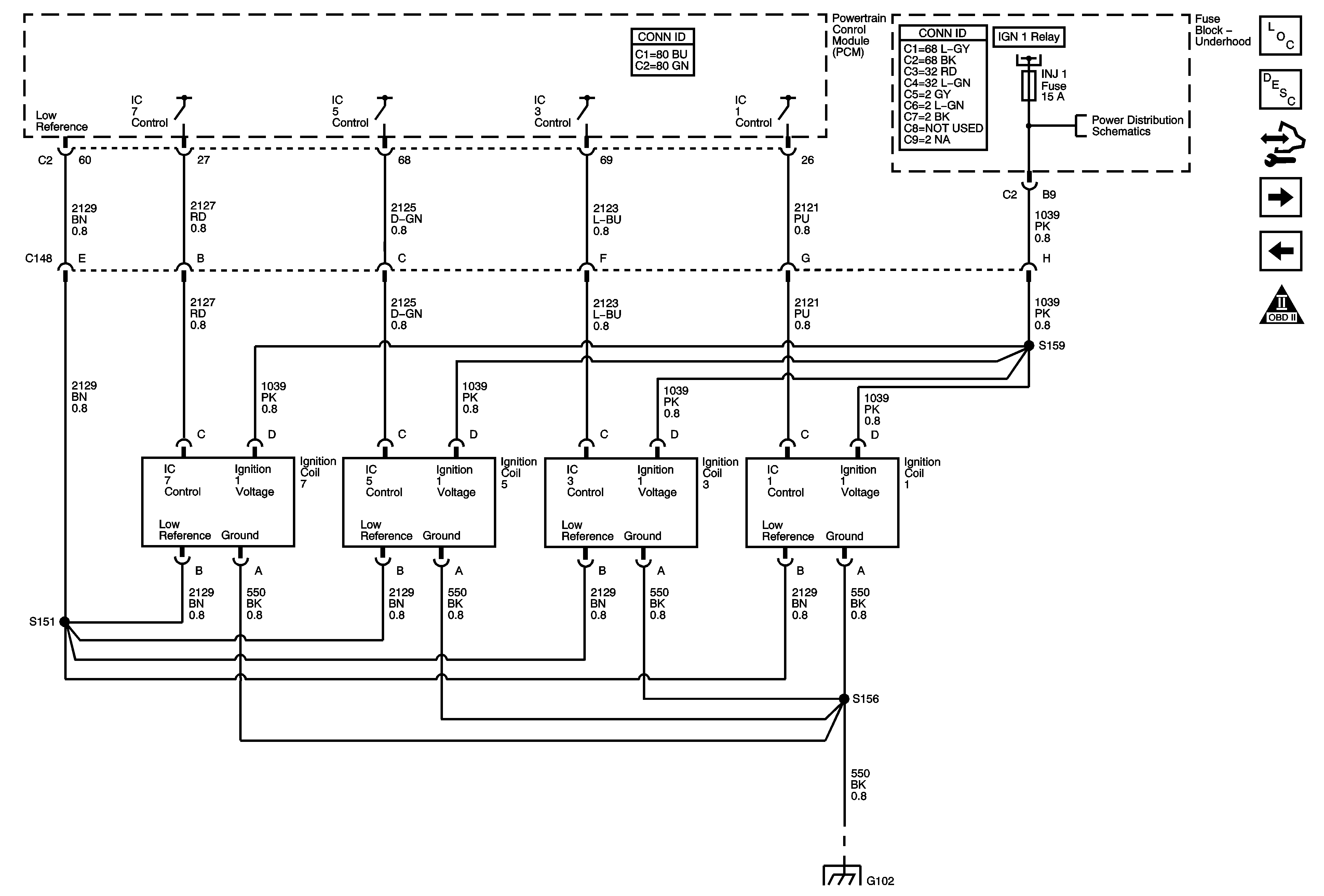

Object Number: 1776774  Size: FS
Master Electrical Component List
Electronic Ignition (EI) System Description
Control Module References
Ignition Controls - Ignition System Coils 2, 4, 6, 8
Engine Data Sensors - Electronic Throttle Control
Engine Controls Schematic Icons
ETC/ECM, INJ1, INJ2, PCM 1, and SBA Fuses - Gas
G100 and G102
Figure 9:

Ignition Controls - Ignition System Coils 2, 4, 6, and 8
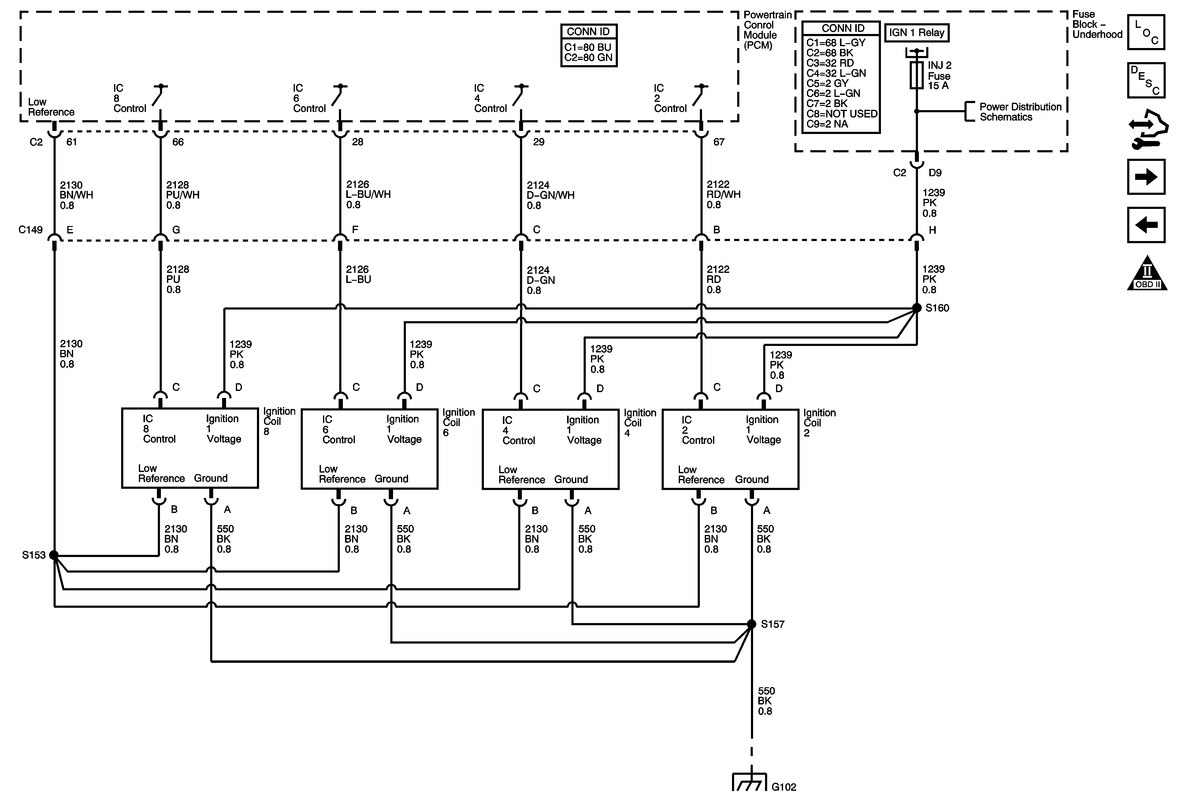

Object Number: 1776777  Size: FS
Master Electrical Component List
Electronic Ignition (EI) System Description
Control Module References
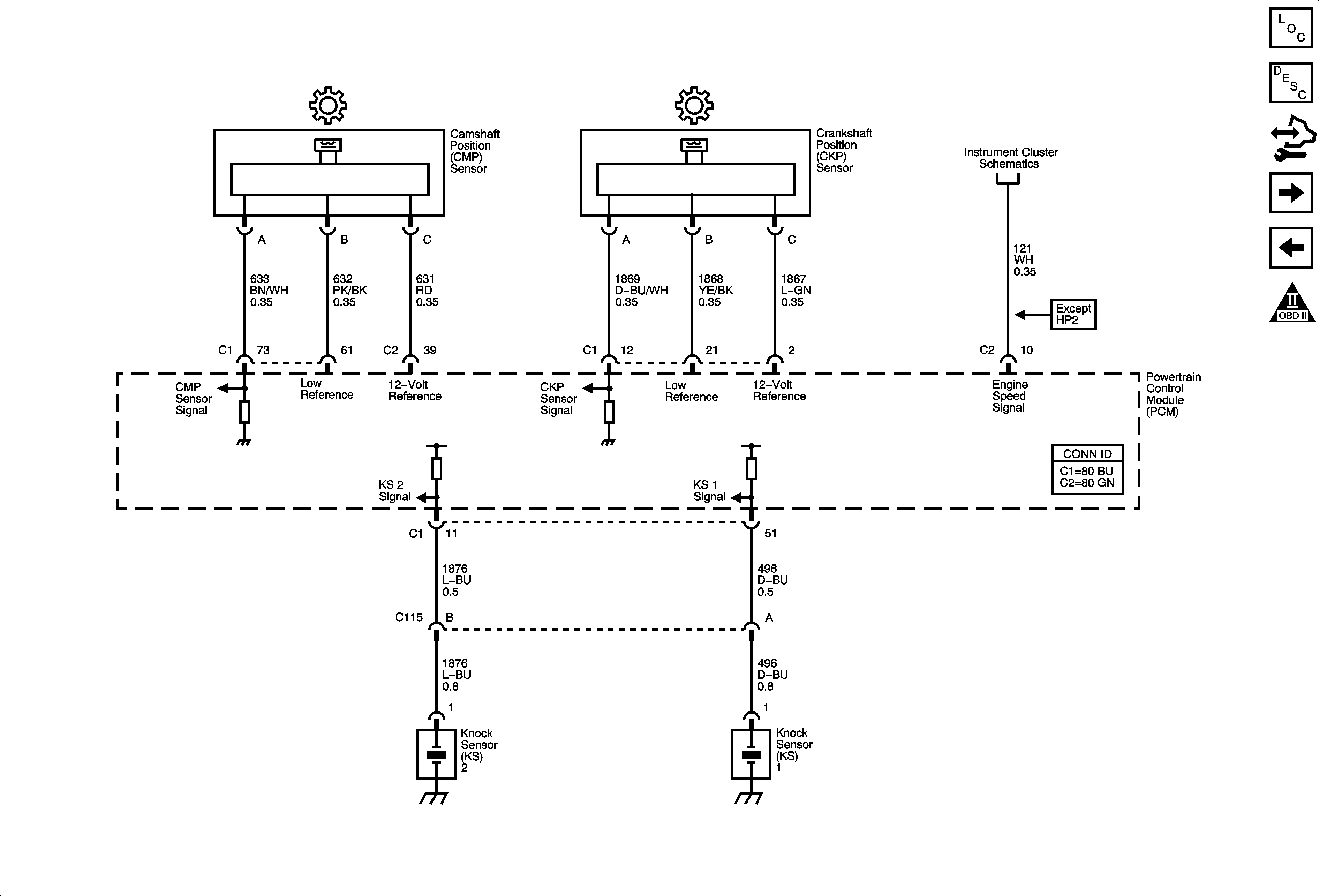
Ignition Controls - Sensors
Ignition Controls - Ignition System Coils 1, 3, 5, 7
Engine Controls Schematic Icons
ETC/ECM, INJ1, INJ2, PCM 1, and SBA Fuses - Gas
G100 and G102
Figure 10:

Ignition Controls - Sensors


Object Number: 1776854  Size: FS
Master Electrical Component List
Powertrain Control Module Description
Control Module References
Fuel Controls - Fuel Pump Controls
Ignition Controls - Ignition System Coils 2, 4, 6, 8
Engine Controls Schematic Icons
Gages, Vehicle Speed Sensor, Engine Oil Pressure, and Fuel Level Sensors
Figure 11:

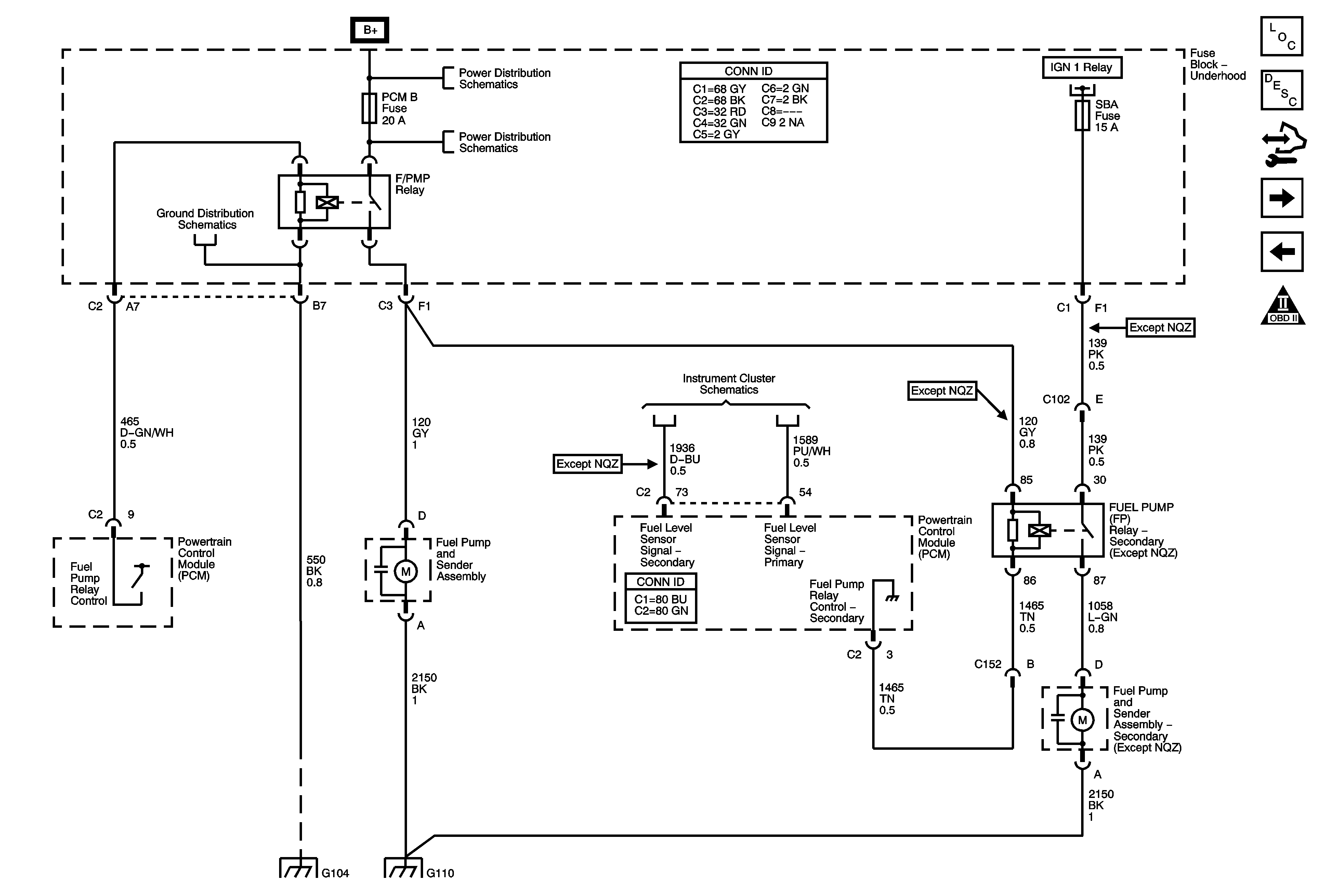
Fuel Controls - Fuel Pump Controls


Object Number: 1776861  Size: FS
Master Electrical Component List
Fuel System Description (Pickup and Utility)
Control Module References
Fuel Controls - Fuel Injectors
Ignition Controls - Sensors
Engine Controls Schematic Icons
B+ Bus Bar
AUX PWR, AUX PWR 2, DDM, ECC/TCM, ECM B, LBEC 2, LCKS, PCM B, PDM, and TCM B Fuses
G104, G107, and G110
Gages, Vehicle Speed Sensor, Engine Oil Pressure, and Fuel Level Sensors
ETC/ECM, INJ1, INJ2, PCM 1, and SBA Fuses - Gas
G104, G107, and G110
Figure 12:

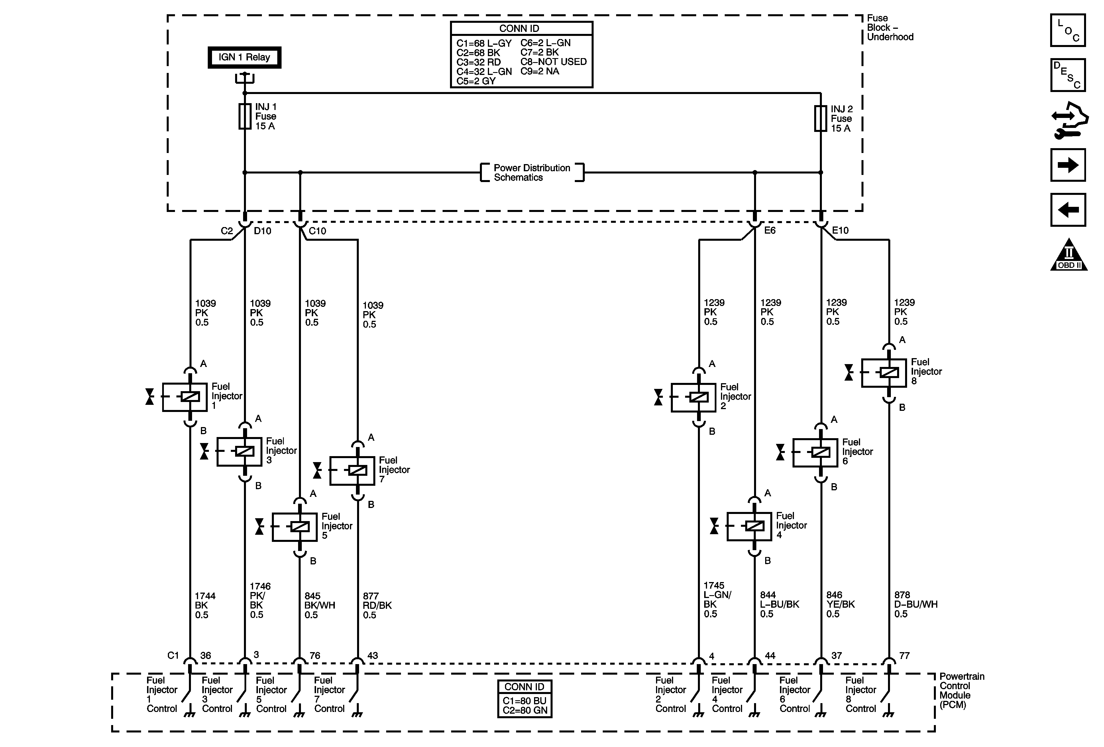
Fuel Controls - Fuel Injectors


Object Number: 1776869  Size: FS
Master Electrical Component List
Fuel System Description (Pickup and Utility)
Control Module References
Fuel Controls - EVAP Controls and FTP Sensor
Fuel Controls - Fuel Pump Controls
Engine Controls Schematic Icons
ETC/ECM, INJ1, INJ2, PCM 1, and SBA Fuses - Gas
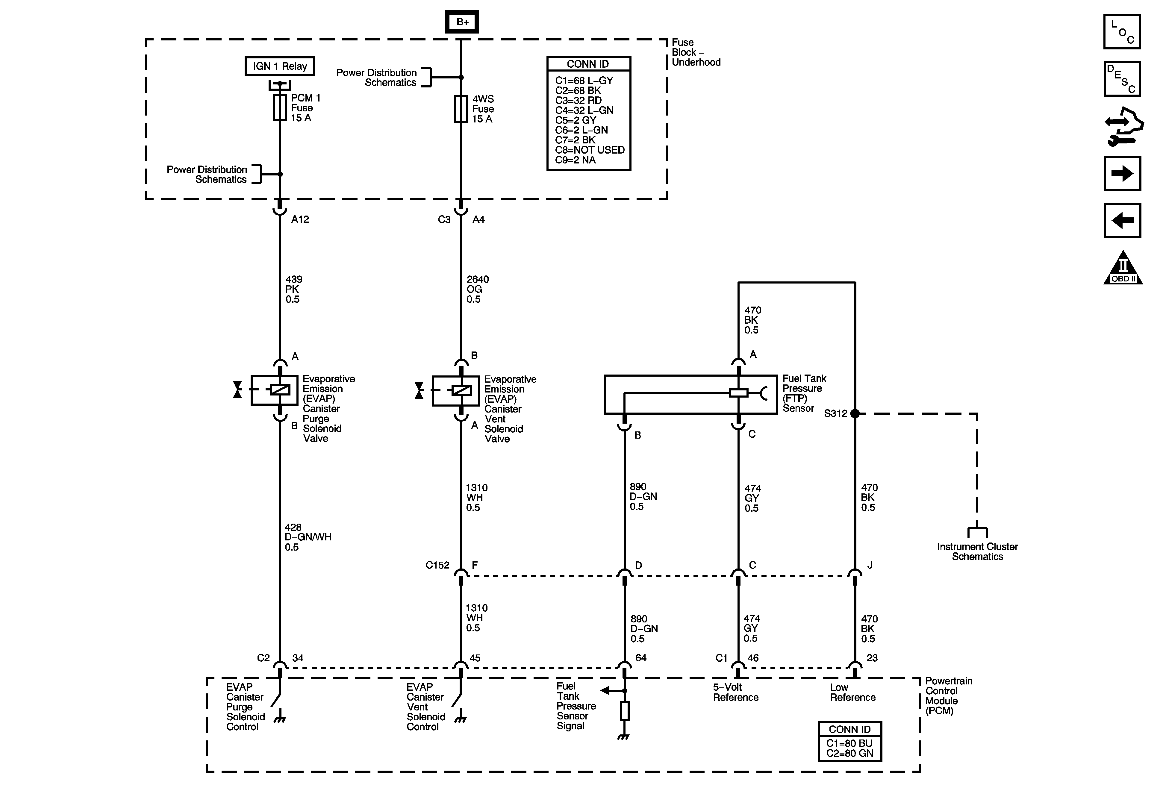
Figure 13:

Fuel Controls - EVAP Controls and FTP Sensor


Object Number: 1776872  Size: FS
Master Electrical Component List
Evaporative Emission Control System Description
Control Module References
Controlled/Monitored Subsystem References
Fuel Controls - Fuel Injectors
Engine Controls Schematic Icons
ETC/ECM, INJ1, INJ2, PCM 1, and SBA Fuses - Gas
B+ Bus Bar
Gages, Vehicle Speed Sensor, Engine Oil Pressure, and Fuel Level Sensors
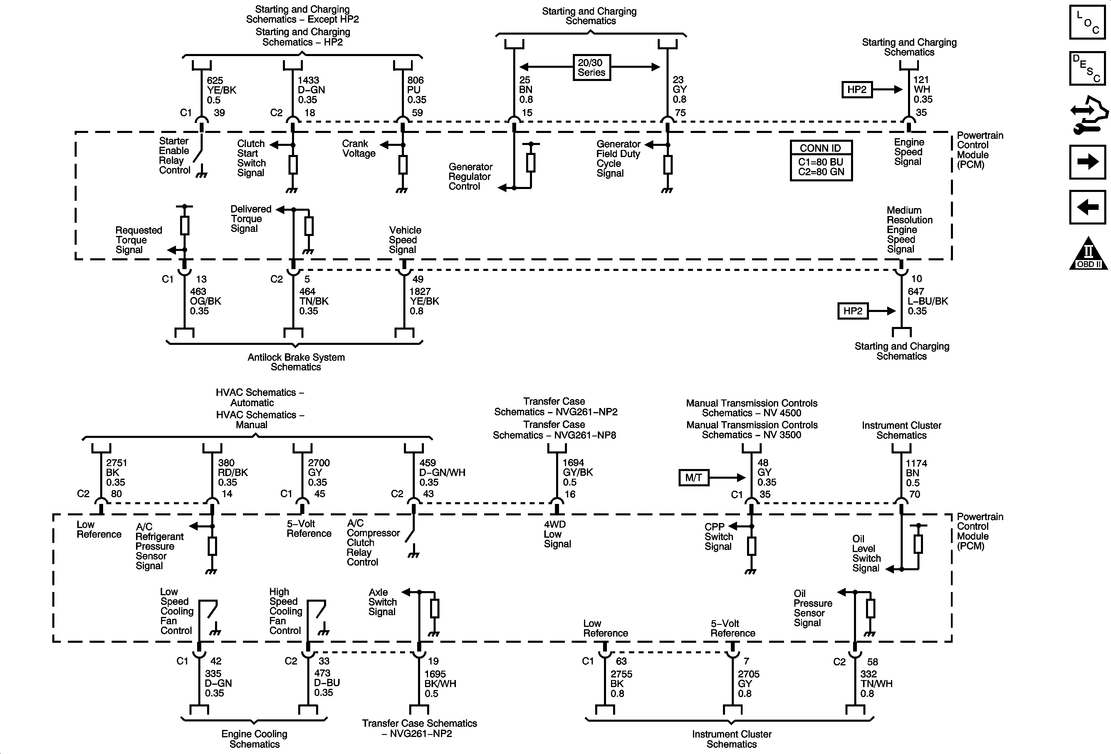
Figure 14:

Controlled/Monitored Subsystem References


Object Number: 1776883  Size: FS
Master Electrical Component List
Powertrain Control Module Description
Control Module References
Transmission Control References
Fuel Controls - EVAP Controls and FTP Sensor
Engine Controls Schematic Icons
Starting - Gas
Starting Controls - 1 of 2
Charging - 20/30 Series - Gas
Starting Controls - 1 of 2
Power, Ground, Serial Data, Indicator and Stop Lamp Switch - 8600 GVW or Less w/ Rear Disc Brakes
A/C Compressor Controls
A/C Compressor Control
Transfer Case NVG 261-NP2 Control Schematics
Power, Ground, Serial Data, and Transfer Case Encoder Motor
Manual Transmission NV4500 Schematics
Manual Transmission NV3500 Schematics
Starting Controls - 1 of 2
Indicators, Water in Fuel Sensor, Engine Oil Level Switch, and Washer Fluid Level Sensor
10 Series
Transfer Case NVG 261-NP2 Control Schematics
Gages, Vehicle Speed Signal, Engine Oil Pressure, and Fuel Level Sensors
Figure 15:

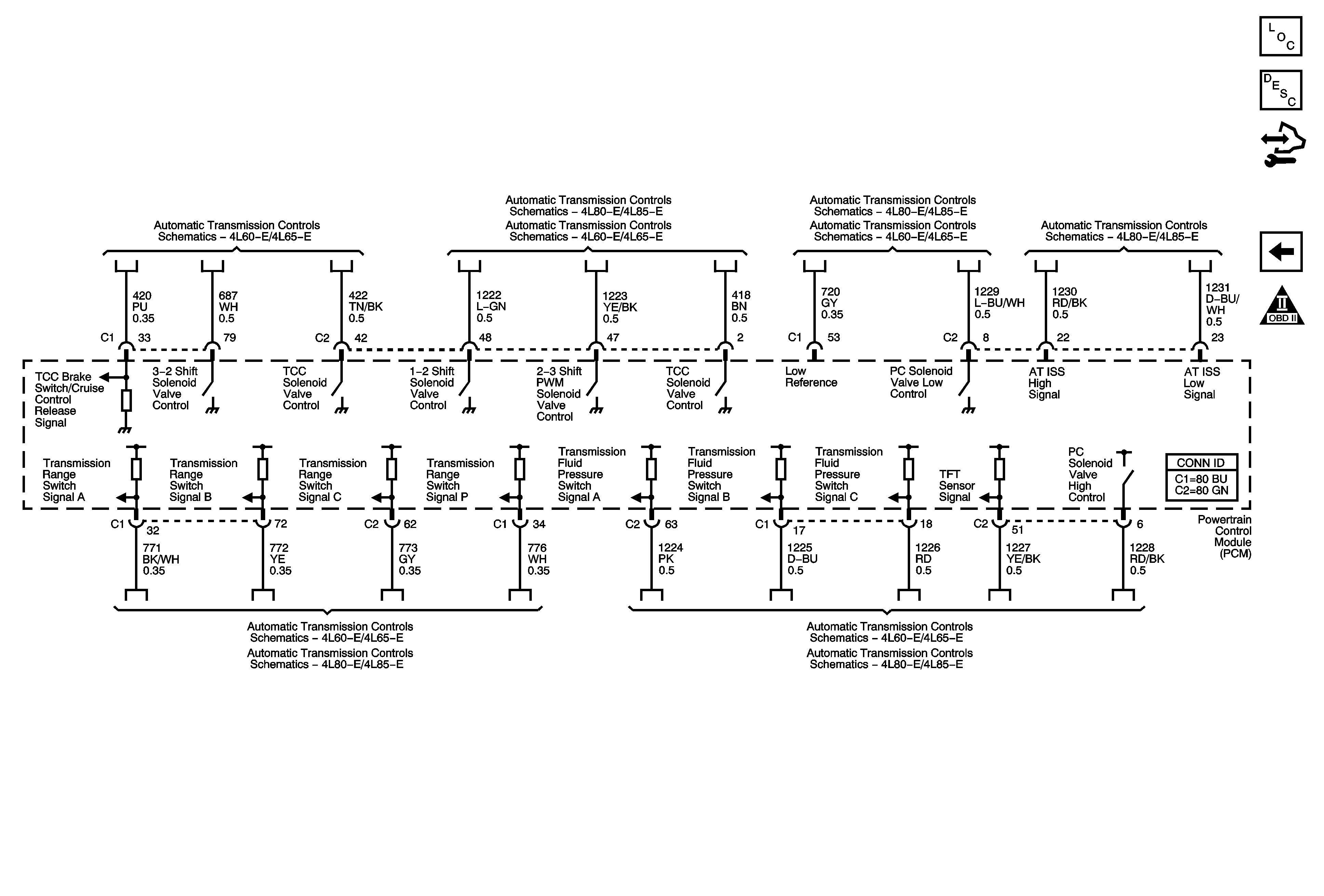
Transmission Control References


Object Number: 1776885  Size: FS
Master Electrical Component List
Powertrain Control Module Description
Control Module References
Controlled/Monitored Subsystem References
Engine Controls Schematic Icons
Shift Controls and Stop Lamp Switch
Pressure Controls, Temperature, and VSS
PNP Switch, 4WD Signal, Tow/Haul, Serial Data, and Indicator
PNP Switch, 4WD Signal, Tow/Haul. Serial Data, and Indicator
Pressure Controls, Temperature, and VSS