GM Service Manual Online
For 1990-2009 cars only
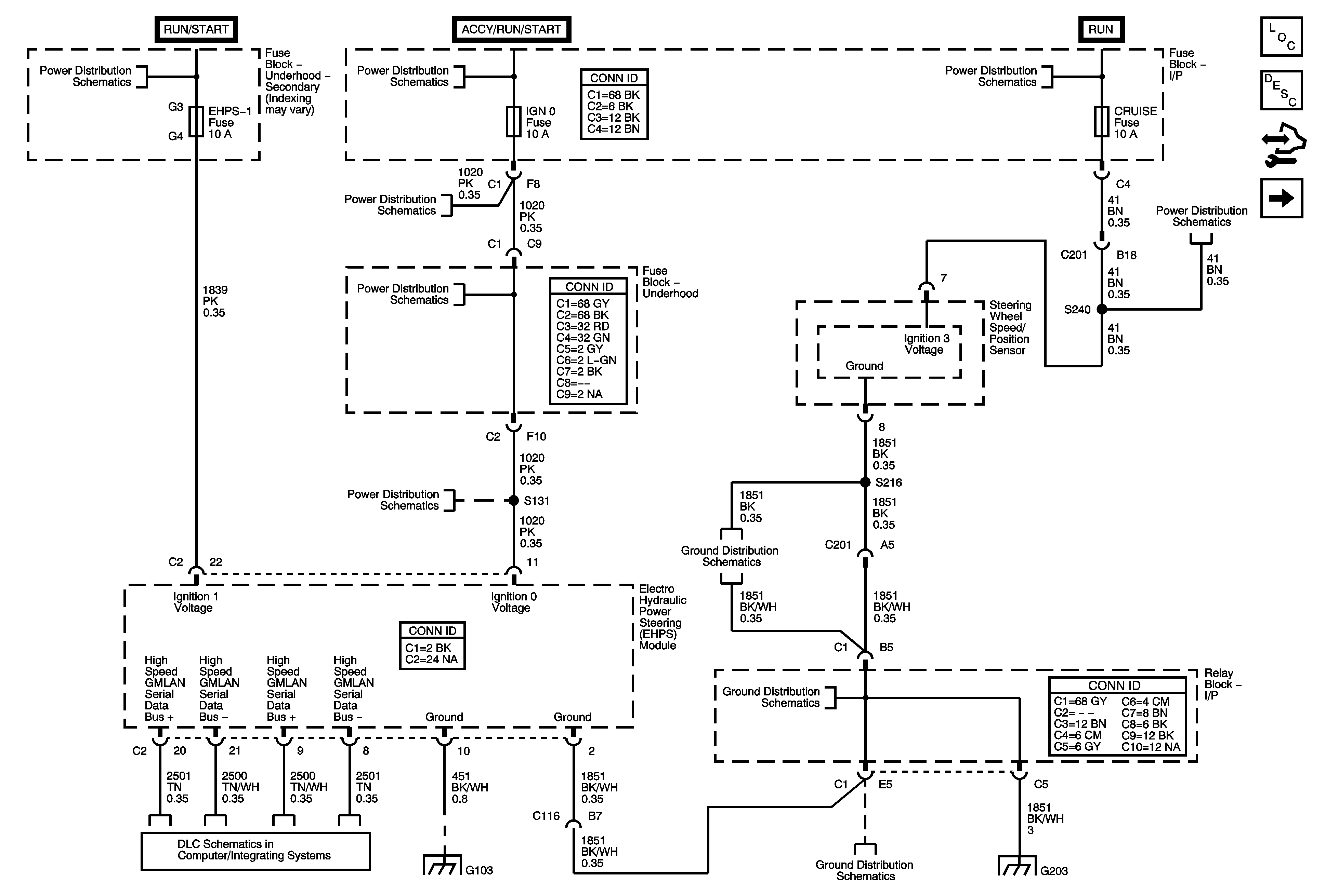
Figure 1:

Power, Ground, and Serial Data


Object Number: 1795360  Size: FS
Master Electrical Component List
Power Steering System Description and Operation (w/ Electro-Hydraulic Steering)
Control Module References
Steering Wheel/Speed and Brake Pedal Position Sensor
Ignition Switch - ACC/RUN and RUN/START BUS BARS and IGN B Fuse
Ignition Switch - START, RUN, and ACC/RUN/START BUS BARS, IGN A, and CRNK Fuses
IGN 0, RR WPR, SEO ACCY, TBC ACCY, TBC IGN 0, and WS WPR Fuses
G203 - 2 of 2
4WD, BRK, CRUISE, HTR/AC, and HVAC 1 Fuses
G203 - 2 of 2
High Speed GM LAN (HP2)
G103 and G106 - Gas
G203 - 1 of 2
G203 - 1 of 2
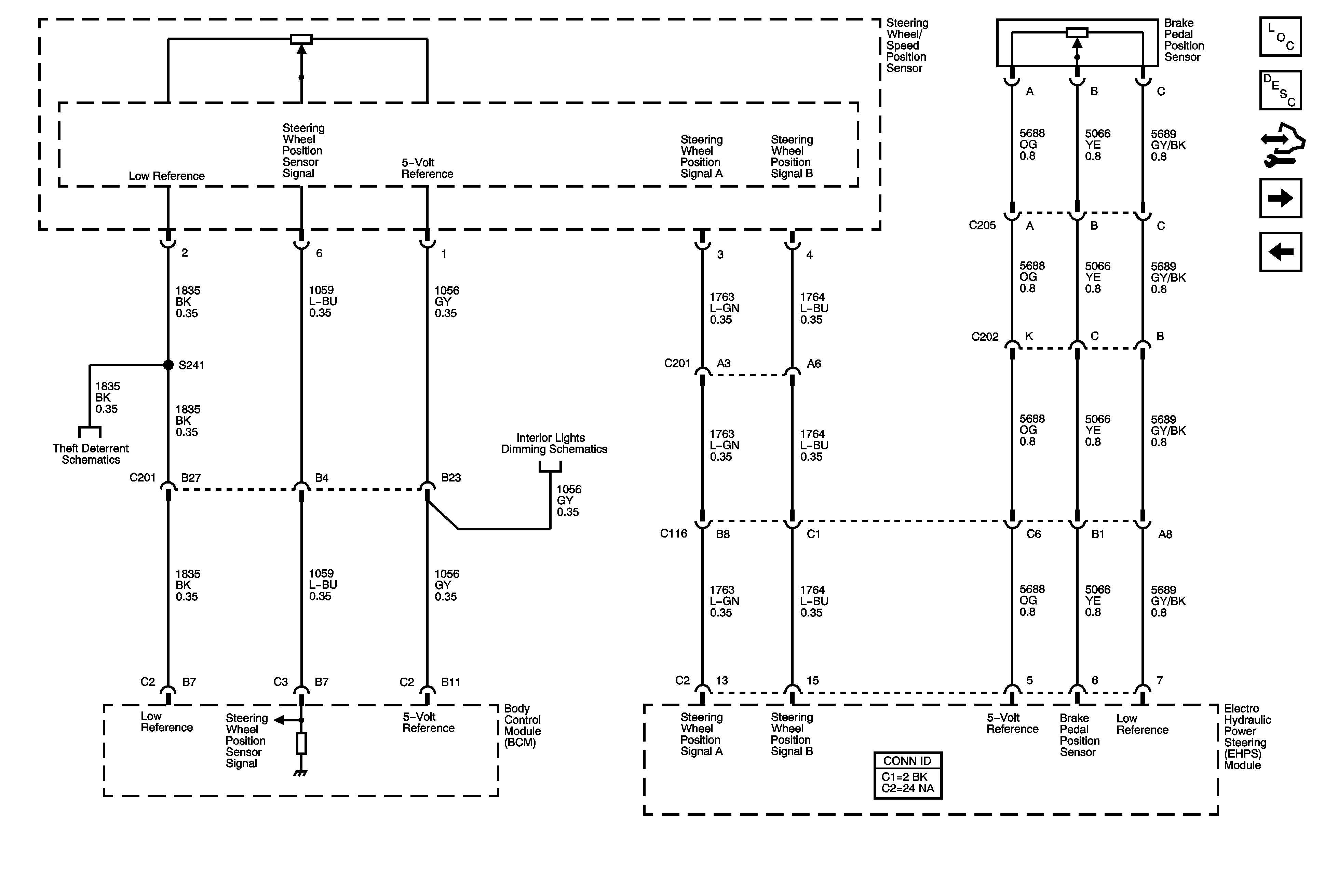
Figure 2:

Steering Wheel/Speed and Brake Pedal Position Sensor


Object Number: 1851819  Size: FS
Master Electrical Component List
Power Steering System Description and Operation (w/ Electro-Hydraulic Steering)
Control Module References
Hydraulic Motor Power and Ground
Power, Ground, and Serial Data
Immobilizer Schematics
Dimming Control and LED Dimming Supply - 1 of 2
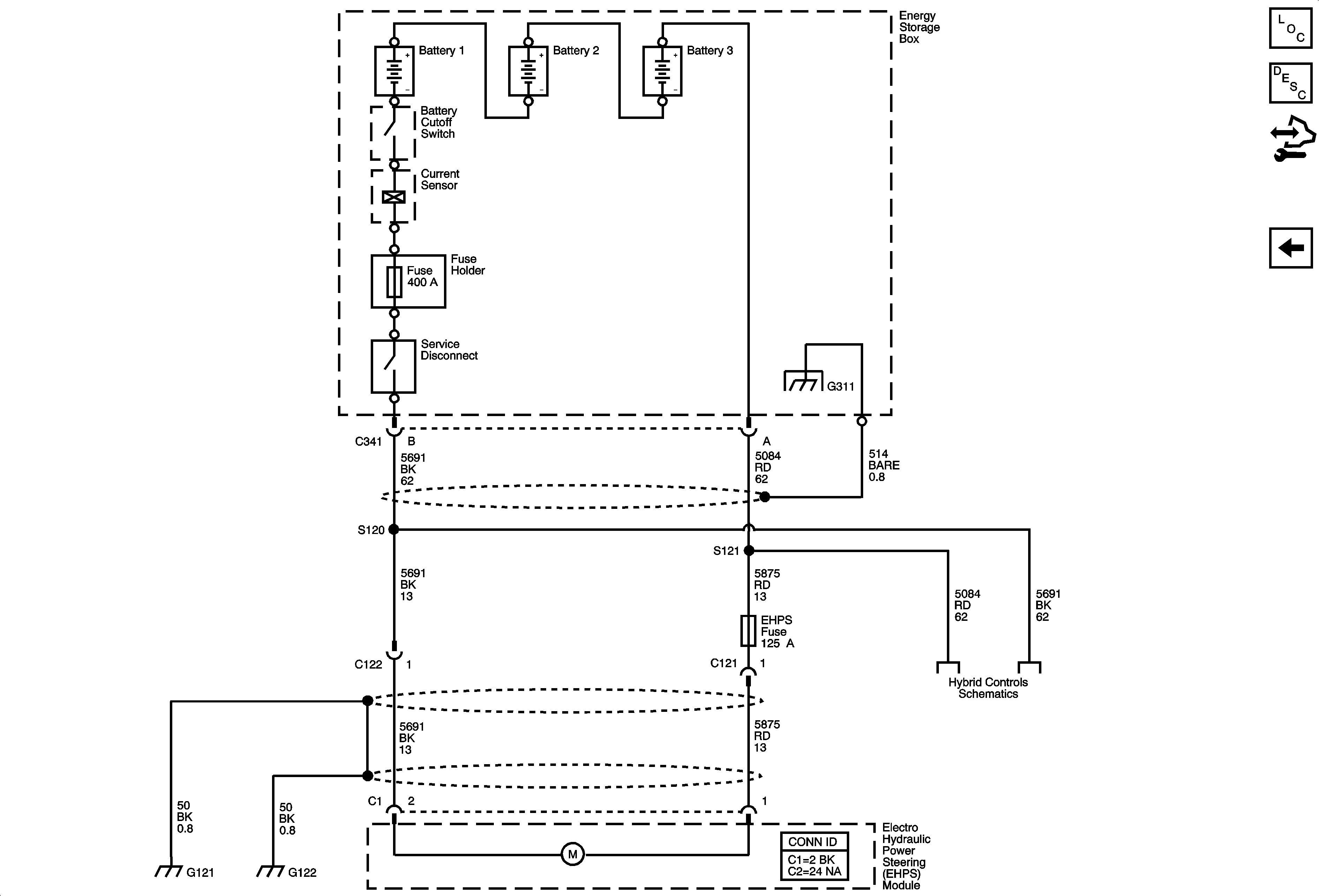
Figure 3:

Hydraulic Motor Power and Ground


Object Number: 1795366  Size: FS
Master Electrical Component List
Power Steering System Description and Operation (w/ Electro-Hydraulic Steering)
Control Module References
Steering Wheel/Speed and Brake Pedal Position Sensor
G120, G121, G122, G310, G311, and G405 (HP2)
Starting - 2 of 2 and Energy Storage