Tools Required
J 42640 Steering Column Anti-Rotation Pin
Removal Procedure
- Disable the SIR system. Refer to SIR Disabling and Enabling.
- Lock the steering column through the access hole in the lower trim cover using J 42640 .
- Remove the steering column from the vehicle. Refer to Steering Column Replacement .
- Remove the sensor connector by using a suitable tool in order to pull the connector down around the right side of the steering column for accessibility.
- Remove the sensor retainer from the steering shaft.
- If reusing the sensor (1), remove the position sensor by pulling the sensor straight out from the bearing adapter (3) until the sensor is almost off the steering shaft (2). Install a pin into the sensor before removing from the steering shaft (2). Do not remove the pin until the sensor is re-installed.
- If replacing the sensor (1), remove the sensor by pulling the sensor straight out from the bearing adapter (3) and off the steering shaft.
Caution: Refer to SIR Caution in the Preface section.
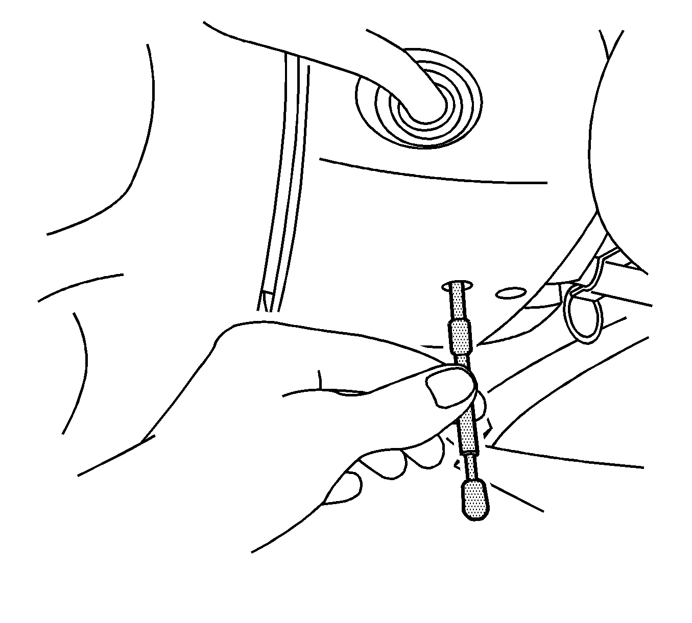
Notice: The front wheels of the vehicle must be maintained in the straight ahead position and the steering column must be in the LOCK position before disconnecting the steering column or intermediate shaft. Failure to follow these procedures will cause improper alignment of some components during installation and result in damage to the SIR coil assembly.
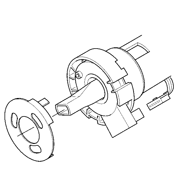
Important: A new sensor must come with a pin installed. If pin is not installed, return and reorder sensor. Do not apply force to the sensor and the bearing assembly in a sideways direction.
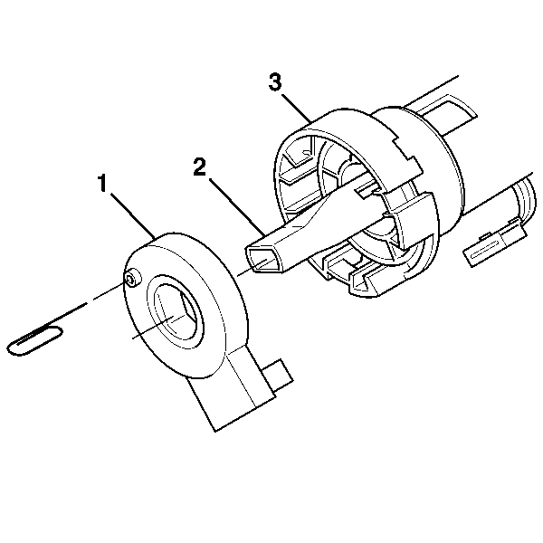
Important: When reusing the sensor (1) you must install a pin into the sensor before it is removed from the steering shaft. By not installing a pin into the sensor it will cause the sensor to lose its centering position and must be discarded.
Pin diameter must be in the range of 1-2 mm. Do not remove the bearing adapter (3).Installation Procedure
- If reusing the sensor, with the pin still installed, align the sensor onto the steering shaft (2) and into the bearing adapter (3).
- Install the sensor onto the steering shaft (2) and into the bearing adapter (3).
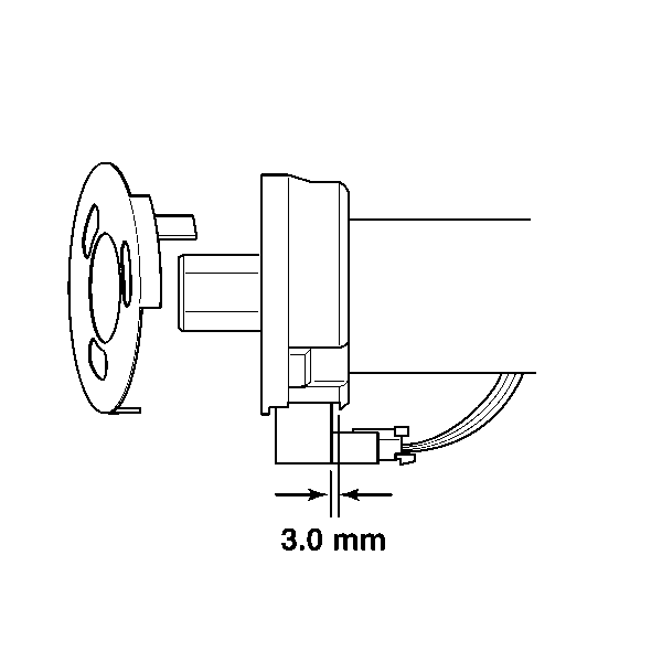
- The sensor must be set to approximately 3 mm gap between the sensor and the bearing adapter.
- Install the sensor connector.
- Remove the pin from the sensor.
- Install the sensor retainer onto the steering shaft.
- Install the steering column to the vehicle. Refer to Steering Column Replacement .
- Remove J 42640 from the steering column.
- Enable the SIR system. Refer to SIR Disabling and Enabling .
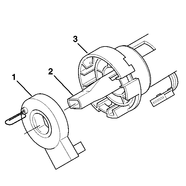
Important: Do not apply force to the sensor (1) or the bearing adapter (3) in a sideways direction.
Important: If installing a new sensor the sensor will come precentered. Do not remove the pin until installation is complete.
