- If reusing the fastener, apply threadlock GM P/N 12345382 (Canadian P/N 10953489) or equivalent, to the threads of the fuel meter body bracket bolt.
- Install the fuel meter body bracket and bolt.
- Install the fuel meter body into the fuel meter body bracket.
- Install the 6 injectors into the proper lower intake manifold bores in proper sequence (3, 5, 1, 2, 4, 6).
- Inspect the injectors in order to ensure that they are firmly seated and locked in the lower intake manifold bores.
- Ensure that the electrical connections of the injectors are positioned so that they do not interfere with each other, and are pointing towards the center of the intake manifold. Rotate the electrical connector inboard if necessary. Also, ensure there is no tension on the injector wires.
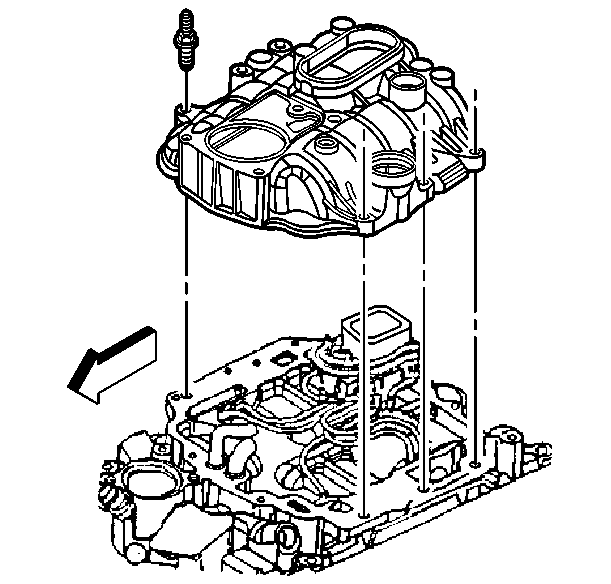
- Install a NEW upper intake manifold to lower intake manifold gasket into the groove of the upper intake manifold.
- Install the upper intake manifold onto the lower intake manifold.
- If reusing the fasteners, apply threadlock GM P/N 12345382 (Canadian P/N 10953489) or equivalent, to the threads of the upper intake manifold attaching studs.
- Install the upper intake manifold attaching studs.
- Tighten the upper intake manifold attaching studs on the first pass to 5 N·m (44 lb in).
- Tighten the upper intake manifold attaching studs on the final pass to 9 N·m (80 lb in).
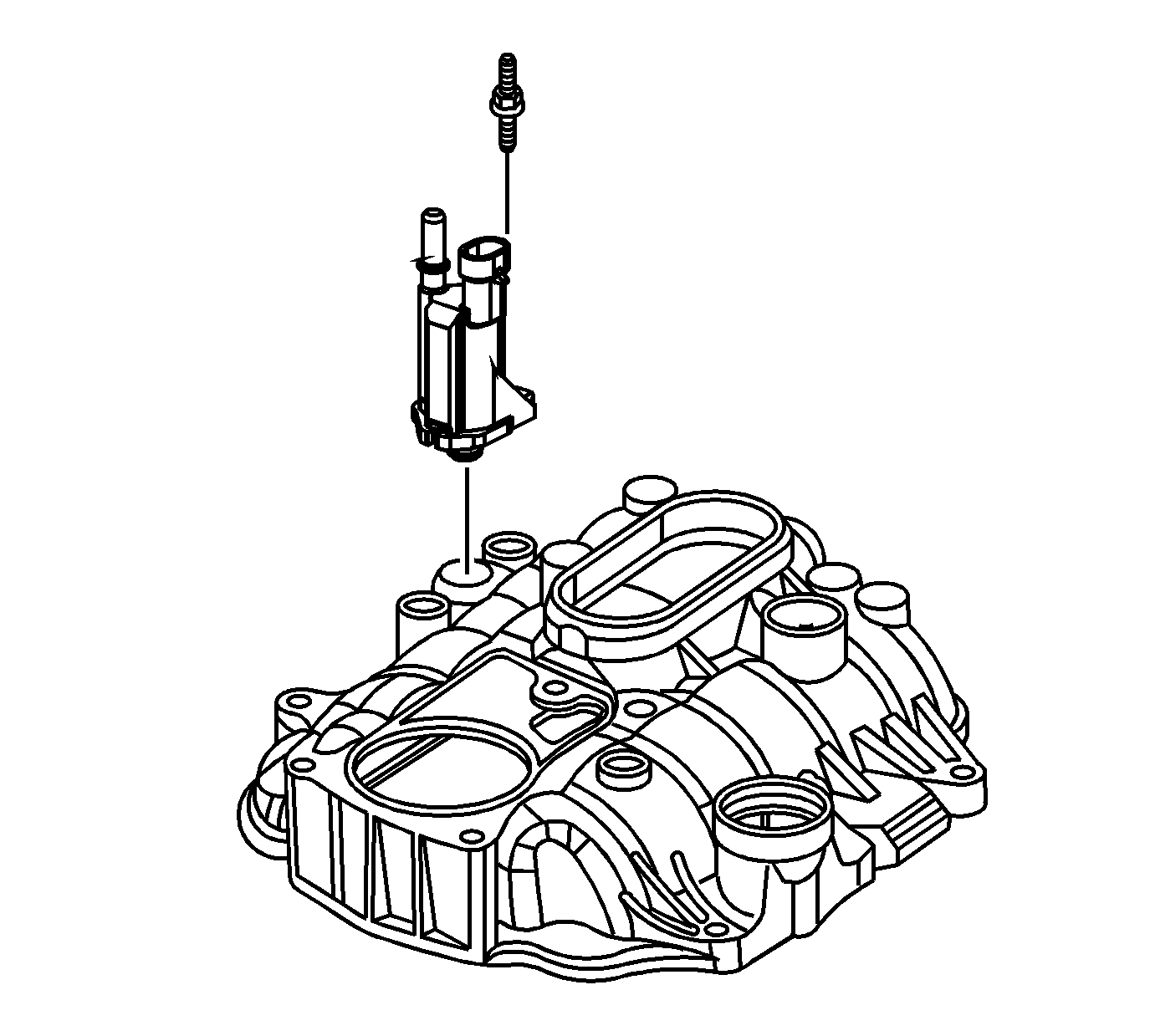
- If reusing the fasteners, apply threadlock GM P/N 12345382 (Canadian P/N 10953489) or equivalent, to the threads of the evaporative emission (EVAP) canister purge solenoid valve studs.
- Install the EVAP canister purge solenoid valve and studs.
- Install the engine wiring harness bracket and nut.
- Install the NEW fuel seals (514), black O-rings, into the fuel meter body.
- Install the NEW spacer rings (513), flat washers, into the fuel meter body.
- Install the NEW fuel seals (512), yellow O-rings, into the fuel meter body.
- Install the NEW fuel seal retainers (511) into the fuel meter body.
- Install the fuel pipe plug (750), if required.
- Install the fuel pipe (749) into the fuel meter body.
- Install the fuel pipe retainer bracket (753) onto the fuel pipe.
- Install the fuel pipe retainer bracket nuts (510).
- If reusing the fastener, apply threadlock GM P/N 12345382 (Canadian P/N 10953489) or equivalent, to the threads of the fuel pipe bolt.
- Install the fuel service port cap (751) and schrader valve (752), if required.
- Install the fuel pipe bolt (509).
- Tighten the fuel pipe bracket nuts to 3 N·m (27 lb in).
- Tighten the fuel pipe bolt to 6 N·m (53 lb in).
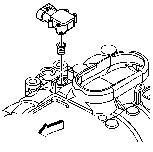
- Install a NEW manifold absolute pressure (MAP) sensor seal onto the MAP sensor.
- Apply a small amount, approximately 1 drop, of clean engine oil to the MAP sensor seal.
- Install the MAP sensor into the upper intake manifold.
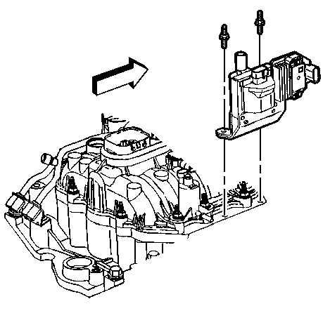
- Install the ignition coil and studs.
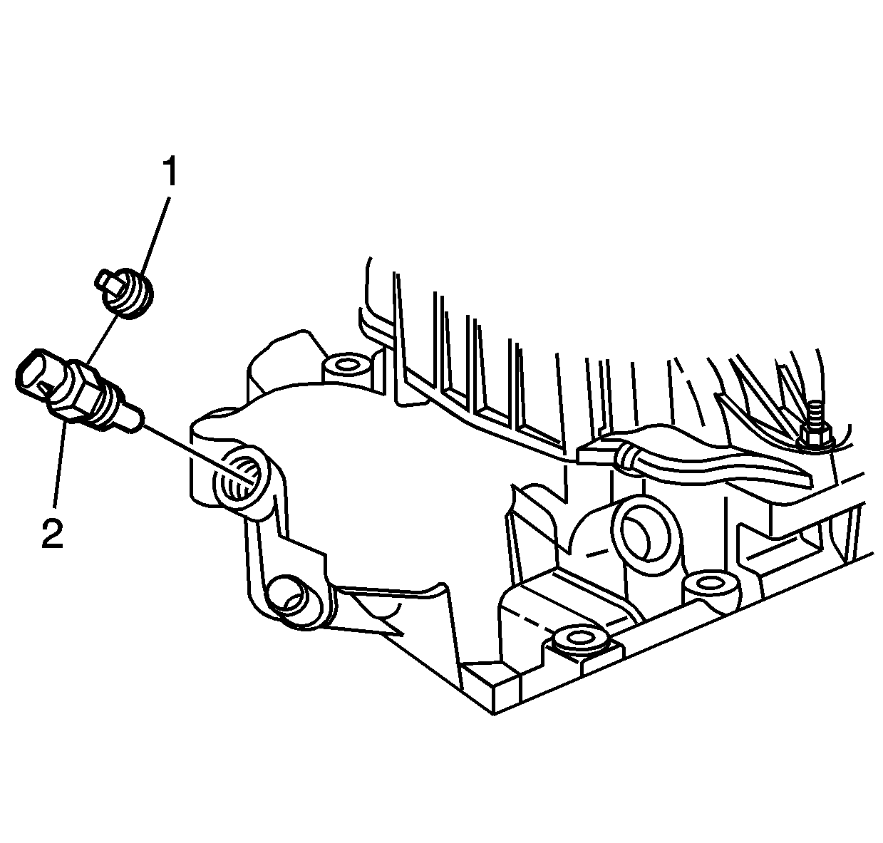
- If reusing the engine coolant temperature (ECT) sensor plug (1) or the ECT sensor (2), if equipped, apply sealant GM P/N 12346004 (Canadian P/N 10953480) or equivalent, to the threads of the ECT sensor plug (1) or the ECT sensor (2).
- Install the ECT sensor or plug, if equipped, into the front of the lower intake manifold.
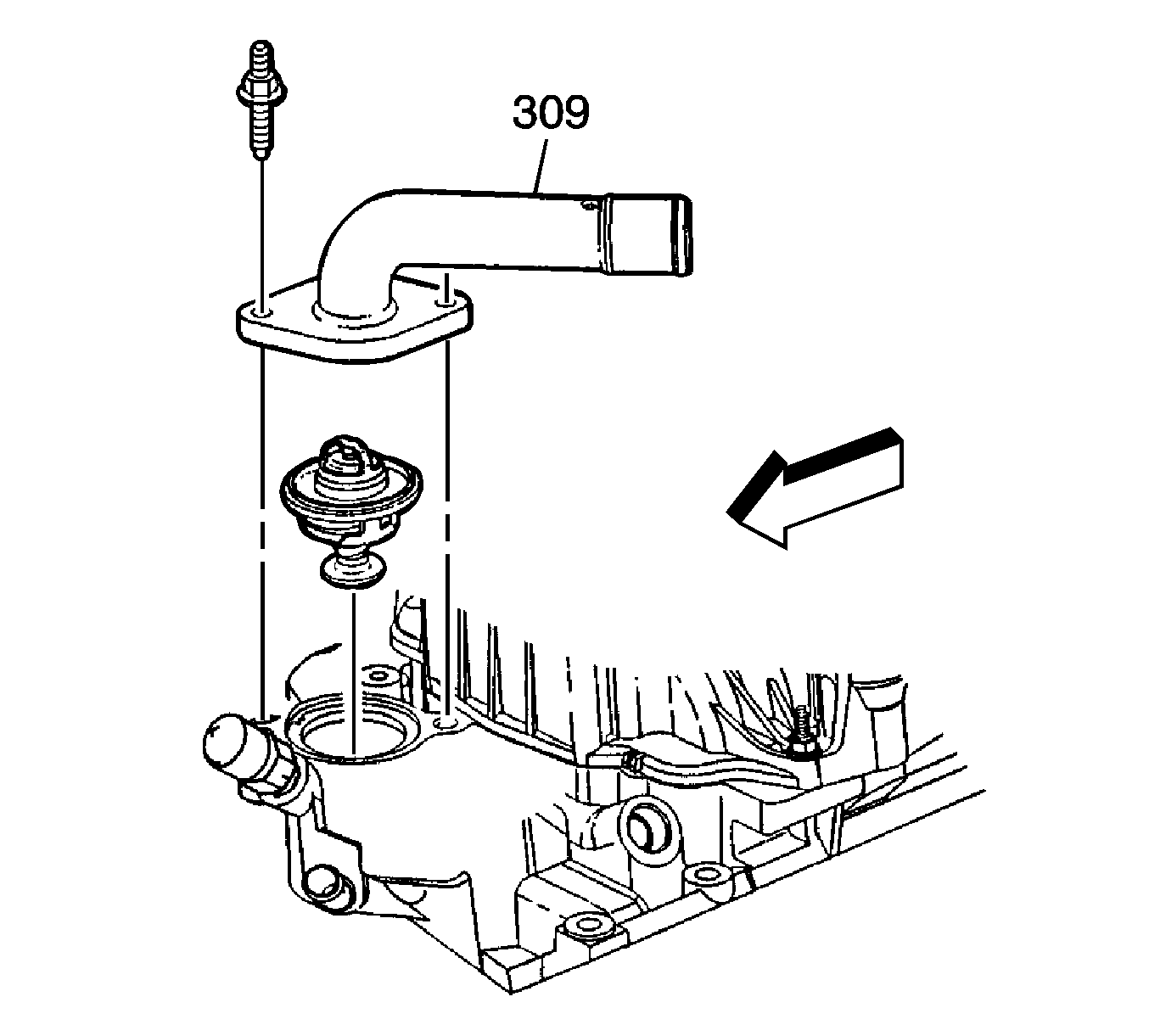
- Install the engine coolant thermostat.
- Install the water outlet (309).
- Install the water outlet studs.
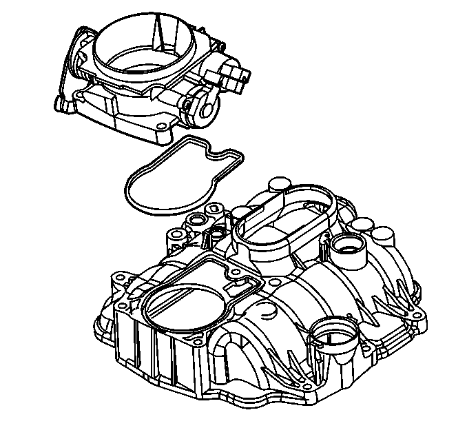
- Install a NEW throttle body gasket into the groove in the upper intake manifold.
- Install the throttle body onto the upper intake manifold.
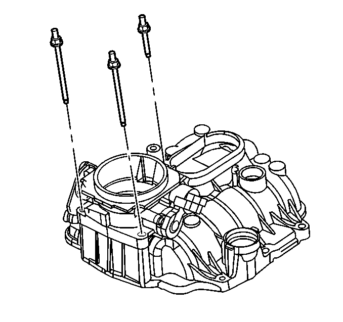
- If reusing the fasteners, apply threadlock GM P/N 12345382 (Canadian P/N 10953489) or equivalent, to the threads of the throttle body attaching studs.
- Install the throttle body attaching studs.
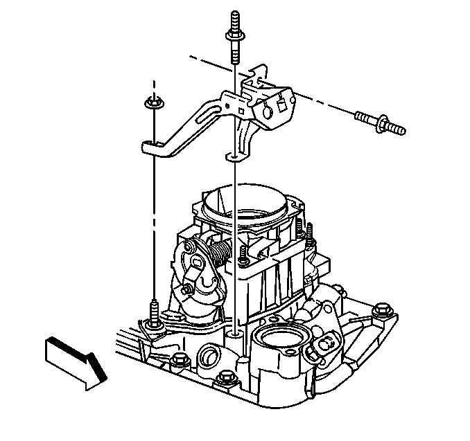
- Install the accelerator control cable bracket, the studs, and the nuts.
- Tighten the accelerator control cable bracket stud to the intake manifold to 6 N·m (53 lb in).
- Tighten the accelerator control cable bracket nuts to 12 N·m (106 lb in).
- Tighten the accelerator control cable bracket stud to the throttle body to 12 N·m (106 lb in).
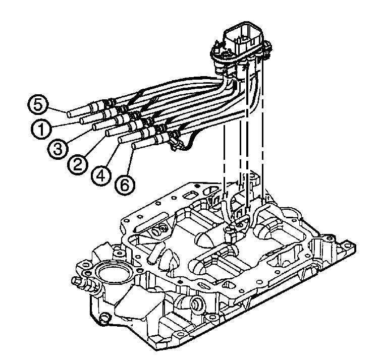
Important: During the removal of the fuel injector assembly, the retainers that hold the injectors into the intake manifold may become worn. This is OK. Upon installation of the upper intake manifold, the injectors will be held fully seated, thus keeping them from backing out of the lower intake manifold.
Notice: Refer to Fastener Notice in the Preface section.
Tighten
Tighten the fuel meter bracket bolt to 10 N·m (89 lb in).
Important: All injector lines must face forward as the fuel meter body is snapped into the bracket. Also, the number 3 fuel tube must be positioned behind the number 1 fuel tube to eliminate interference with the upper intake manifold when installed.
Tighten
Tighten
Tighten the EVAP canister purge solenoid valve studs to 10 N·m (89 lb in).
Tighten
Tighten the engine wiring harness bracket nut to 12 N·m (106 lb in).
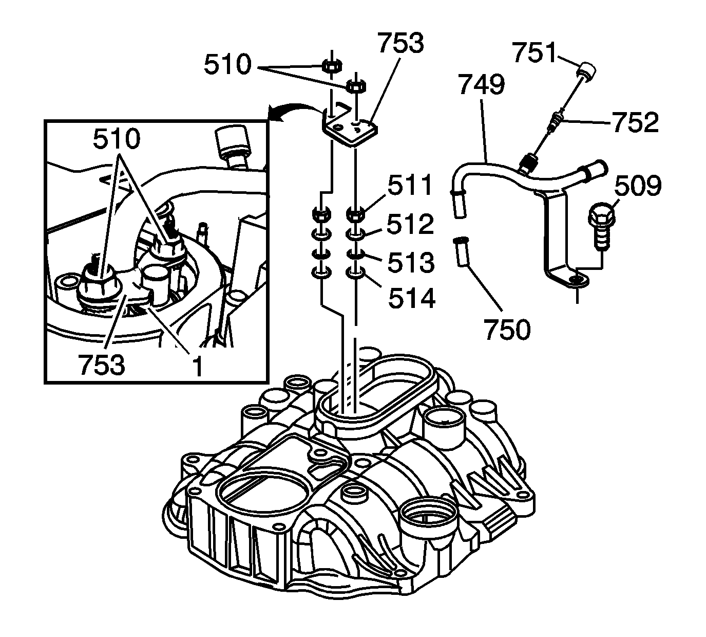
Important: Make sure to properly align the fuel line retainer flanges (1) to face downward towards the fuel meter body, and that flanges rest on the shoulders of the fuel plug and the fuel line. Failure to do so may cause the fuel plug and the fuel line to come out of the fuel meter body, resulting in fuel spillage.
Tighten
Tighten
Tighten the ignition coil studs to 12 N·m (106 lb in).
Tighten
Tighten the ECT sensor or plug to 20 N·m (15 lb ft).
Tighten
Tighten the water outlet studs to 25 N·m (18 lb ft).
Tighten
Tighten the throttle body attaching studs to 9 N·m (80 lb in).
Tighten
