For 1990-2009 cars only
Removal Procedure
- Remove the water outlet. Refer to Water Outlet Tube Replacement .
- Remove the intake manifold tube. Refer to Intake Manifold Tube Replacement .
- Remove the glow plug control module and bracket. Refer to Glow Plug Control Module Replacement .
- Remove the fuel temperature sensor. Refer to Fuel Temperature Sensor Replacement .
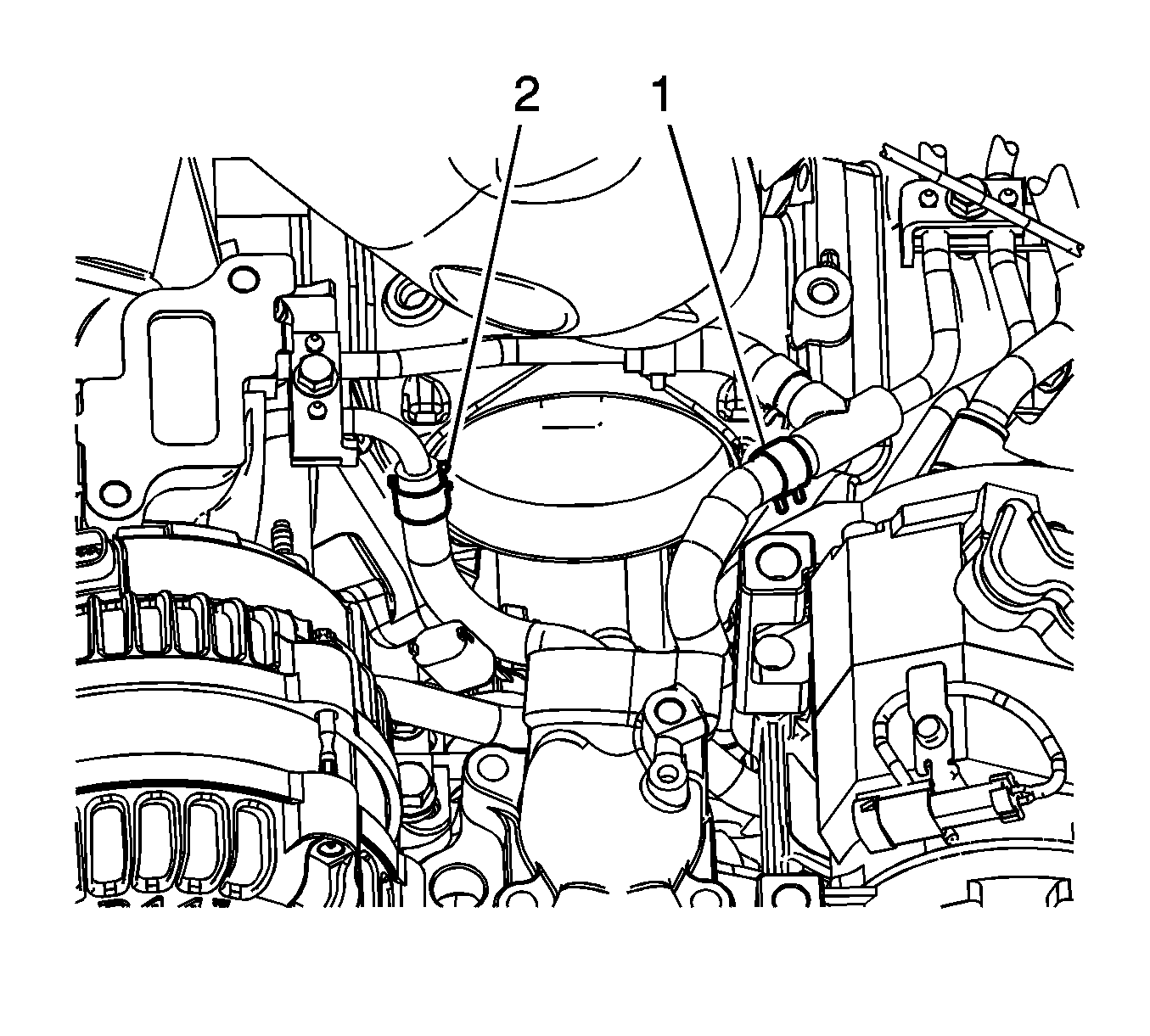
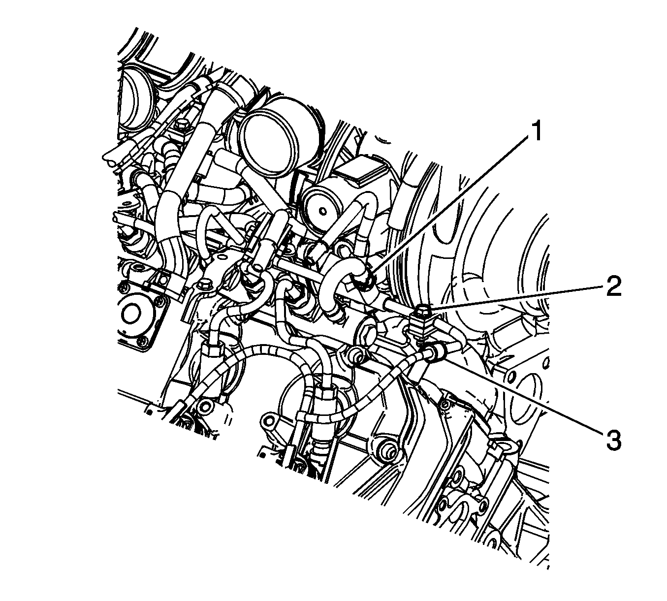
- Reposition the fuel hose clamp (1) at the fuel return pipe.
- Remove the fuel hose (1) from the return pipe.
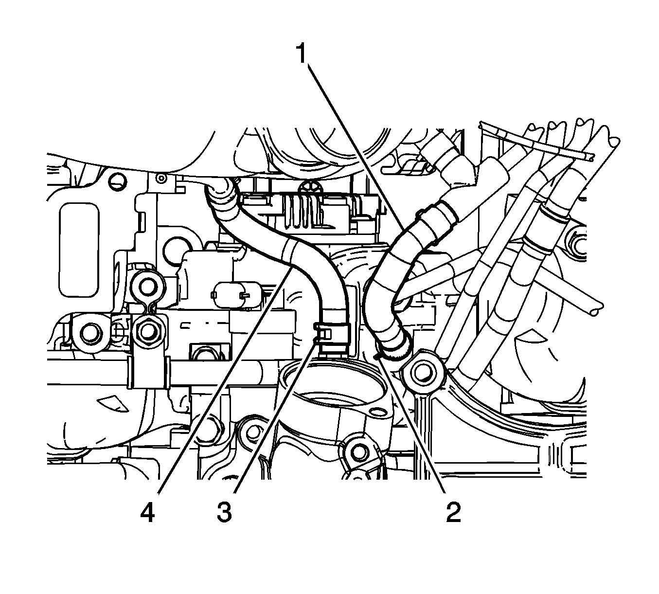
- Reposition the fuel return hose clamp (2) at the fuel return pipe.
- Remove the fuel return pipe clip bolt (2) and clip.
- Remove the fuel return pipe clamp bolt (1) and bracket.
- Reposition the fuel return hose clamp (1) at the return pipe.
- Remove the fuel return hose from the return pipe.
- Remove the fuel return pipe clamp bolt (2) and clamp.
- Disconnect the fuel injection fuel feed pipe (3) from the fuel return pipe.
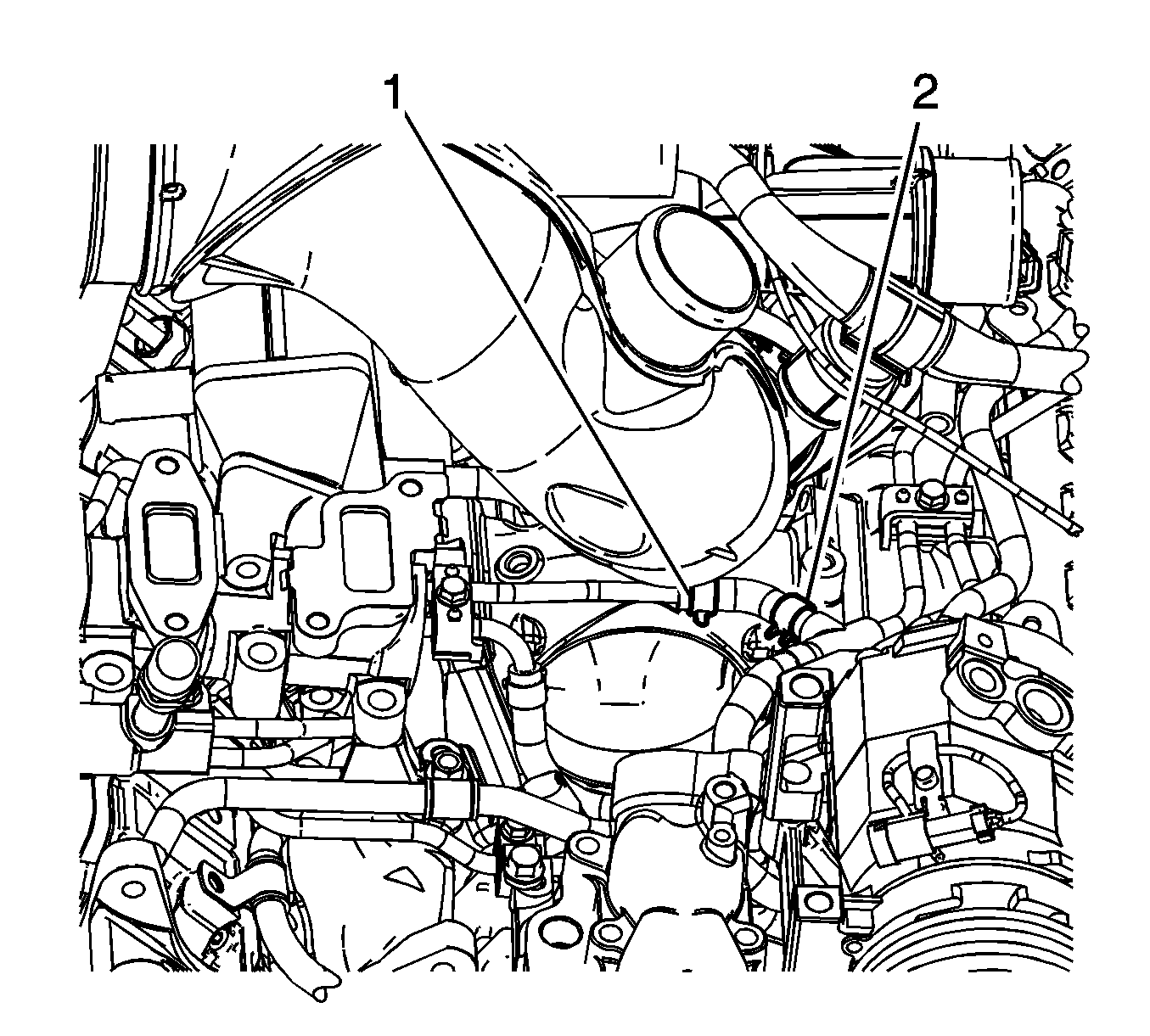
- Remove the fuel return pipe from the fuel return hose and the vehicle.
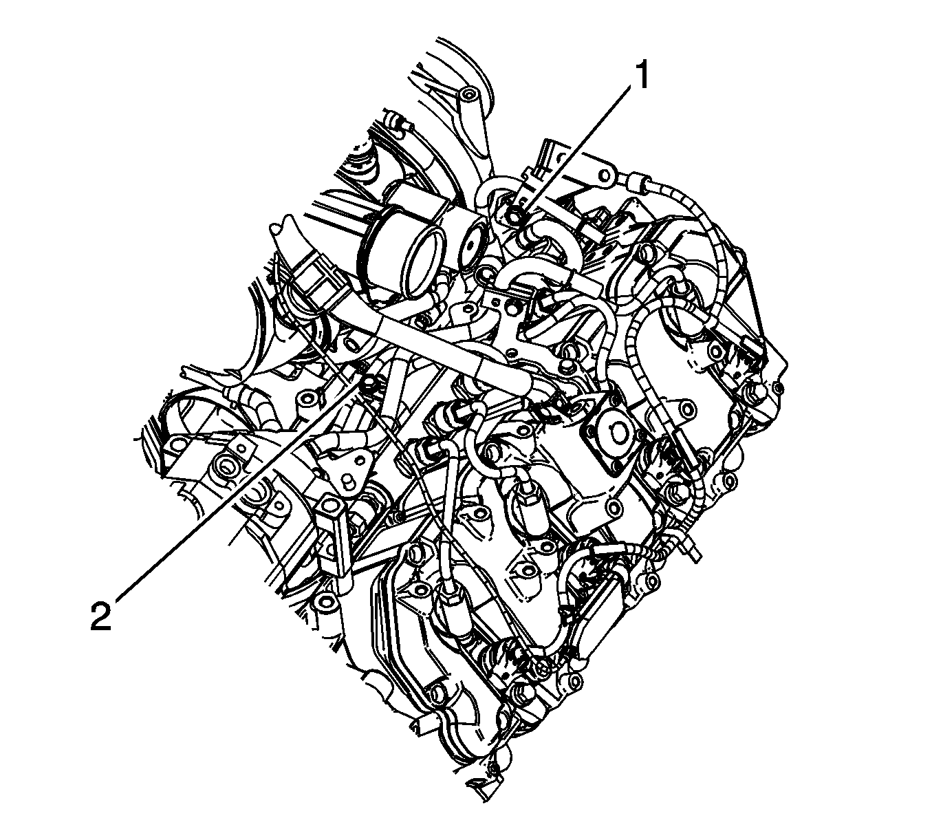
Important: Engine wiring harness shown removed for clarity.
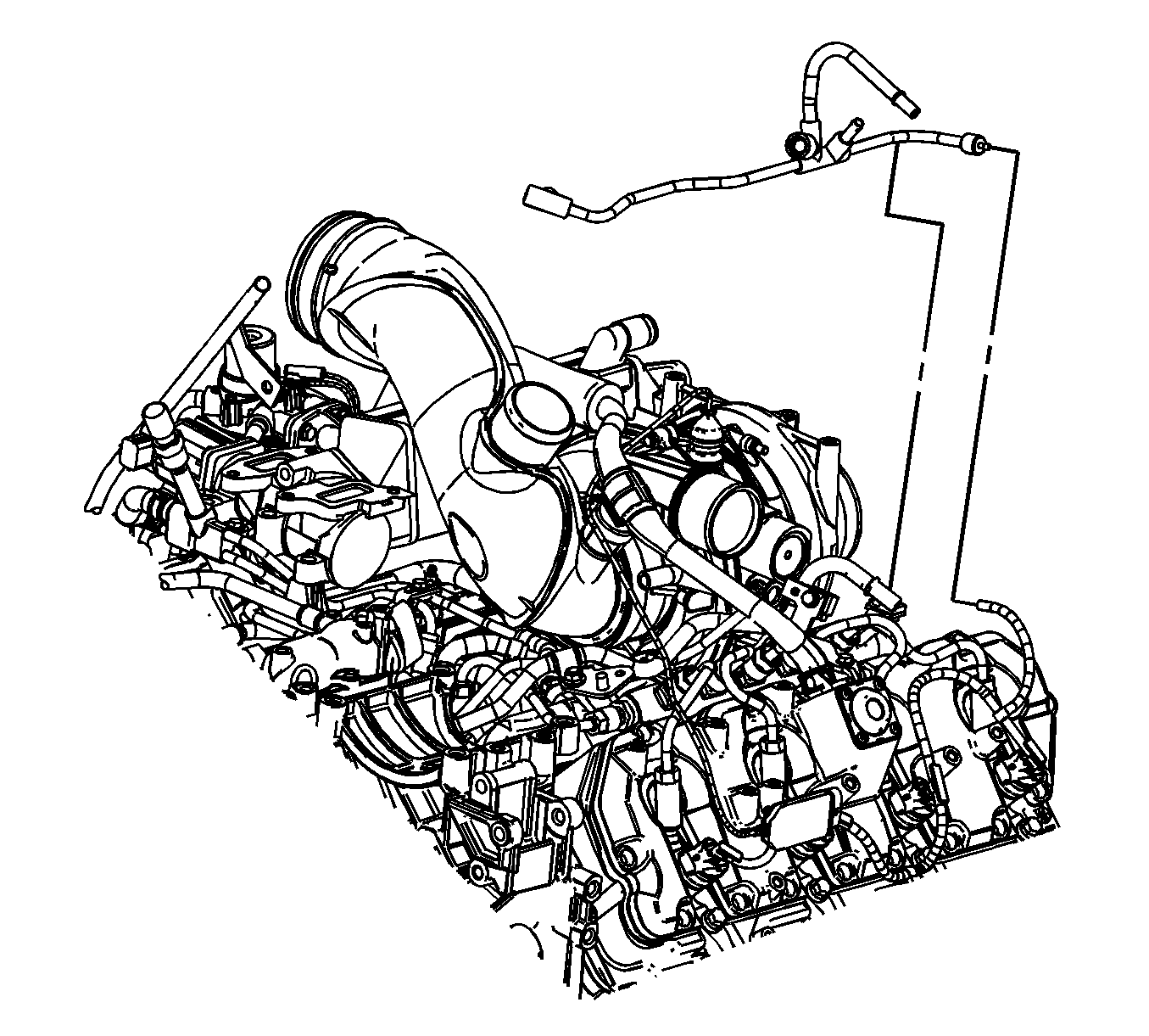
Important: Note the routing of the fuel return pipe prior to removal.
Installation Procedure
- Position and install the fuel return pipe to the vehicle and the fuel return hose.
- Connect the fuel injection fuel feed pipe (3) to the fuel return pipe.
- Position and install the fuel return pipe clamp and bolt (2).
- Install the fuel return hose to the return pipe.
- Position the fuel return hose clamp (1) at the return pipe.
- Install the fuel return pipe bracket, clamp, and bolt (1).
- Install the fuel return pipe clip and bolt (2).
- Position the fuel return hose clamp (2) at the fuel return pipe.
- Install the fuel hose (1) to the return pipe.
- Position the fuel hose clamp (1) at the fuel return pipe.
- Install the fuel temperature sensor. Refer to Fuel Temperature Sensor Replacement .
- Install the glow plug control module and bracket. Refer to Glow Plug Control Module Replacement .
- Install the intake manifold tube. Refer to Intake Manifold Tube Replacement .
- Install the water outlet. Refer to Water Outlet Tube Replacement .
- Prime the fuel system. Refer to Fuel System Priming .
- Start the engine. If the engine stalls, repeat the above step.
- Once the engine starts, inspect for fuel leaks.
Important: Ensure to route the fuel return pipe under the wiring harness and noted during removal.
Notice: Refer to Fastener Notice in the Preface section.
Tighten
Tighten the bolt to 24 N·m (18 lb ft).
Tighten
Tighten the bolt to 24 N·m (18 lb ft).
Tighten
Tighten the bolt to 24 N·m (18 lb ft).
