X100 Forward Lamp Harness to Left Front Headlamp Harness
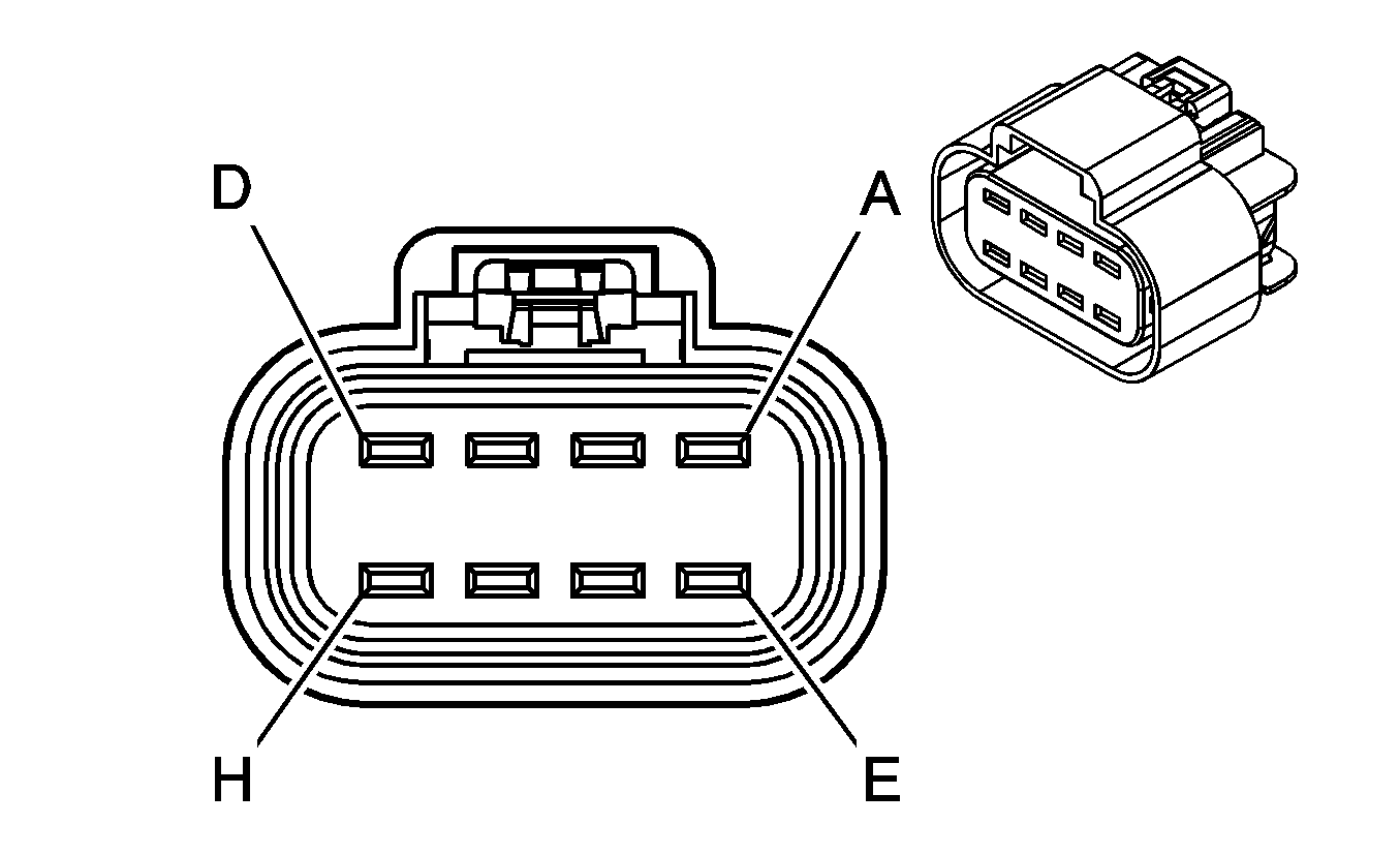
|
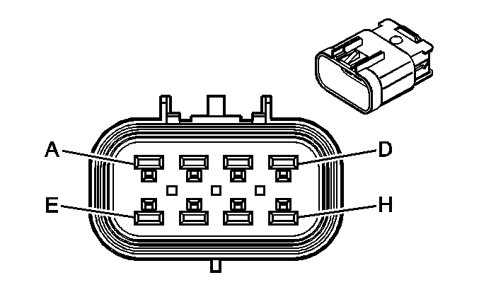
|
Connector Part Information
| Connector Part Information
|
Terminal Part Information
| Terminal Part Information
|
Pin | Wire Color | Circuit No. | Function | Pin | Wire Color | Circuit No. | Function |
|---|---|---|---|---|---|---|---|
A | 0.8 YE | 712 | Left Headlamp Low Beam Supply Voltage | A | 0.8 YE | 712 | Left Headlamp Low Beam Supply Voltage |
B | 1 BK | 150 | Ground | B | 1 BK | 150 | Ground |
C | 0.5 D-GN/WH | 711 | Left Headlamp High Beam Supply Voltage | C | 0.8 D-GN/WH | 711 | Left Headlamp High Beam Supply Voltage (X88) |
0.8 OG | 711 | Left Headlamp High Beam Supply Voltage (Z88) | |||||
D | -- | -- | Not Used | D | -- | -- | Not Used |
E | 0.5 BN | 2509 | Left Front Park Lamps Supply Voltage | E | 0.8 BN | 2509 | Left Front Park Lamps Supply Voltage (X88) |
0.8 L-GN | 2509 | Left Front Park Lamps Supply Voltage (Z88) | |||||
F | 1 BK | 150 | Ground | F | 0.8 BK | 150 | Ground (X88) |
0.8 GY | 150 | Ground (Z88) | |||||
G | 0.8 L-BU/WH | 1314 | Left Front Turn Signal Lamp Supply Voltage | G | 1 L-BU/WH | 1314 | Left Front Turn Signal Lamp Supply Voltage (X88) |
1 BN | 1314 | Left Front Turn Signal Lamp Supply Voltage (Z88) | |||||
H | -- | -- | Not Used | H | -- | -- | Not Used |
X103 Instrument Panel Harness to Forward Lamp Harness
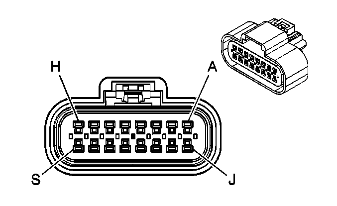
|
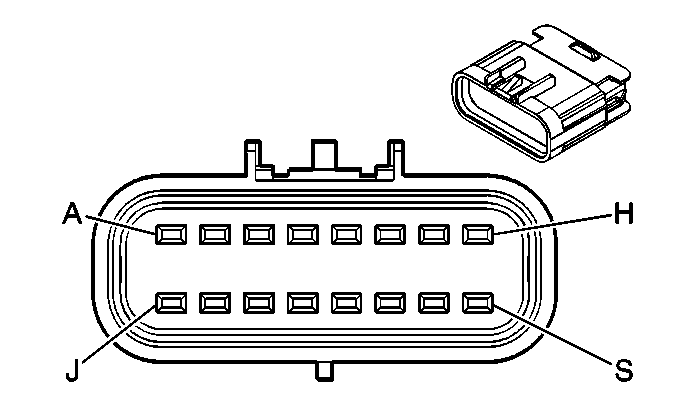
|
Connector Part Information
| Connector Part Information
|
Terminal Part Information
| Terminal Part Information
|
Pin | Wire Color | Circuit No. | Function | Pin | Wire Color | Circuit No. | Function |
|---|---|---|---|---|---|---|---|
A | 0.5 TN/OG | 5045 | Low Reference | A | 0.5 TN/OG | 5045 | Low Reference |
B | 0.5 YE | 354 | Left Front Discriminating Sensor Signal | B | 0.5 YE | 354 | Left Front Discriminating Sensor Signal |
C | 0.5 GY | 5600 | Low Reference (10 Series) | C | 0.5 GY | 5600 | Low Reference (10 Series) |
D | 0.5 D-GN | 1409 | Right Front Discriminating Sensor Signal (10 Series) | D | 0.5 D-GN | 1409 | Right Front Discriminating Sensor Signal (10 Series) |
E | -- | -- | Not Used | E | -- | -- | Not Used |
F | 0.35 TN | 185 | Low Washer Fluid Indicator Control | F | 0.5 TN | 185 | Low Washer Fluid Indicator Control |
G | 0.35 PK/BK | 109 | Hood Ajar Switch Signal (AP3/AP8) | G | 0.5 PK/BK | 109 | Hood Ajar Switch Signal (AP3/AP8) |
H | 0.35 PU | 5531 | Hood Closed Switch Signal (AP3/AP8) | H | 0.5 PU | 5531 | Hood Closed Switch Signal (AP3/AP8) |
J-L | -- | -- | Not Used | J-L | -- | -- | Not Used |
M | 0.35 D-GN/WH | 636 | Ambient Air Temperature Sensor Signal (DF5) | M | 0.5 D-GN/WH | 636 | Ambient Air Temperature Sensor Signal (DF5) |
N | 0.35 YE | 61 | Low Reference (DF5) | N | 0.5 YE | 61 | Low Reference (DF5) |
P | 0.35 L-GN/BK | 735 | Ambient Air Temperature Sensor Signal (CJ2) | P | 0.5 L-GN/BK | 735 | Ambient Air Temperature Sensor Signal (CJ2) |
R | 0.35 D-GN | 6101 | Low Reference (CJ2) | R | 0.5 D-GN | 6101 | Low Reference (CJ2) |
S | -- | -- | Not Used | S | -- | -- | Not Used |
X106 Forward Lamp Harness to Right Front Headlamp Harness

|

|
Connector Part Information
| Connector Part Information
|
Terminal Part Information
| Terminal Part Information
|
Pin | Wire Color | Circuit No. | Function | Pin | Wire Color | Circuit No. | Function |
|---|---|---|---|---|---|---|---|
A | 0.8 TN/WH | 312 | Right Headlamp Low Beam Supply Voltage | A | 0.8 YE | 312 | Right Headlamp Low Beam Supply Voltage |
B | 1 BK | 250 | Ground | B | 1 BK | 250 | Ground |
C | 0.5 L-GN/BK | 311 | Right Headlamp High Beam Supply Voltage | C | 0.8 L-GN/BK | 311 | Right Headlamp High Beam Supply Voltage (X88) |
0.8 OG | 311 | Right Headlamp High Beam Supply Voltage (Z88) | |||||
D | -- | -- | Not Used | D | -- | -- | Not Used |
E | 0.5 BN | 2609 | Right Front Park Lamps Supply Voltage | E | 0.8 BN | 2609 | Right Front Park Lamps Supply Voltage (X88) |
0.8 L-GN | 2609 | Right Front Park Lamps Supply Voltage (Z88) | |||||
F | 1 BK | 250 | Ground | F | 0.8 BK | 250 | Ground (X88) |
0.8 GY | 250 | Ground (Z88) | |||||
G | 0.8 D-BU/WH | 1315 | Right Front Turn Signal Lamp Supply Voltage | G | 1 L-BU/WH | 1315 | Right Front Turn Signal Lamp Supply Voltage (X88) |
1 BN | 1315 | Right Front Turn Signal Lamp Supply Voltage (Z88) | |||||
H | -- | -- | Not Used | H | -- | -- | Not Used |
X107 Engine Chassis Harness to Engine Harness (Diesel)
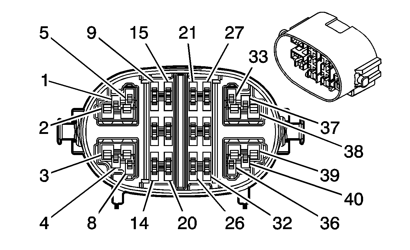
|
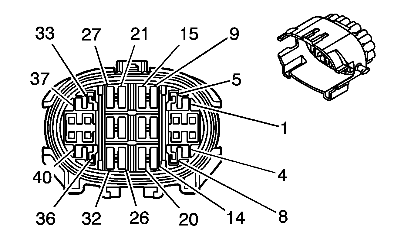
|
Connector Part Information
| Connector Part Information
|
Terminal Part Information
| Terminal Part Information
|
Pin | Wire Color | Circuit No. | Function | Pin | Wire Color | Circuit No. | Function |
|---|---|---|---|---|---|---|---|
1 | 0.5 L-GN | 2032 | ECT Sensor Signal | 1 | 0.5 L-GN | IC50 | ECT Sensor Signal |
2 | 1 OG | 5421 | Fuel Injector Supply Voltage 1 | 2 | 2 OG | IC10 | Fuel Injector Supply Voltage 1 |
3 | 1 YE | 5422 | Fuel Injector Supply Voltage 2 | 3 | 2 YE | IC11 | Fuel Injector Supply Voltage 2 |
4 | 0.5 YE | 410 | ECT Sensor Signal | 4 | 0.5 YE | IC41 | ECT Sensor Signal |
5 | 0.5 L-BU/BK | 6813 | Low Reference | 5 | 0.5 D-BU/BK | IC51 | Low Reference |
6 | 1 TN | 1744 | Fuel Injector 1 Control | 6 | 2 TN | IC15 | Fuel Injector 1 Control |
7 | 1 YE/BK | 846 | Fuel Injector 6 Control | 7 | 2 YE/BK | IC20 | Fuel Injector 6 Control |
8 | 0.5 TN | 2761 | Low Reference | 8 | 0.5 TN | IC47 | Low Reference |
9 | 0.5 PK | 2239 | Ignition 1 Voltage | 9 | 0.85 PK | IC95 | Ignition 1 Voltage |
10 | 0.8 YE | 581 | Motor Control - 1 | 10 | 0.75 YE | IC156 | Motor Control - 1 |
11 | 0.8 BN | 582 | Motor Control - 2 | 11 | 0.75 BN | IC151 | Motor Control - 2 |
12 | 0.5 D-GN | 485 | TP Sensor Signal | 12 | 0.5 D-GN | IC153 | TP Sensor Signal |
13 | 0.5 TN | 2572 | Low Reference | 13 | 0.5 TN | IC154 | Low Reference |
14 | 0.5 GY | 2701 | 5-Volt Reference | 14 | 0.5 GY | IC150 | 5-Volt Reference |
15 | 0.5 GY/BK | 5765 | Fuel Filter Pressure Switch Signal | 15 | -- | -- | Not Used |
16 | 0.35 PU/WH | 7584 | Not Used | 16 | 0.5 PU/WH | IC145 | Not Used |
17 | 0.35 BN | 6274 | Not Used | 17 | 0.5 BN | IC146 | Not Used |
18 | 0.5 BN | 1174 | Oil Level Switch Signal | 18 | 0.5 BN | IC68 | Oil Level Switch Signal |
19 | 0.35 WH | 6275 | Not Used | 19 | 0.35 WH | IC148 | Not Used |
20 | 0.35 D-BU | 7583 | Not Used | 20 | 0.35 D-BU | IC147 | Not Used |
21-26 | -- | -- | Not Used | 21-26 | -- | -- | Not Used |
27 | 0.5 YE/BK | 508 | Water In Fuel Indicator Control | 27 | 0.5 YE/BK | IC90 | Water In Fuel Indicator Control |
28 | 0.5 GY | 2702 | 5-Volt Reference | 28 | 0.5 GY | IC142 | 5-Volt Reference |
29 | 0.5 TN | 2753 | Low Reference | 29 | 0.5 TN | IC143 | Low Reference |
30 | 0.5 BN/WH | 5763 | EGR Valve Sensor Signal | 30 | 0.5 BN/WH | IC144 | EGR Valve Sensor Signal |
31 | 0.5 L-GN/BK | 5746 | EGR Valve Motor Low Control | 31 | 0.5 L-GN/BK | IC141 | EGR Valve Motor Low Control |
32 | 0.5 OG/BK | 5764 | Exhaust Gas Recirculation Valve Motor high Control | 32 | 0.5 OG/BK | IC140 | Exhaust Gas Recirculation Valve Motor high Control |
33 | 0.5 YE | 2834 | Fuel Pressure Regulator Solenoid Control | 33 | 0.5 YE | IC31 | Fuel Pressure Regulator Solenoid Control |
34 | 1 OG/BK | 877 | Fuel Injector 7 Control | 34 | 2 OG/BK | IC21 | Fuel Injector 7 Control |
35 | 1 L-BU/BK | 844 | Fuel Injector 4 Control | 35 | 2 L-BU/BK | IC18 | Fuel Injector 4 Control |
36 | 0.5 BN | 6062 | Low Reference | 36 | 0.5 BN | IC44 | Low Reference |
37 | 0.5 PU/WH | 2530 | Fuel Pressure Regulator Solenoid Supply Voltage | 37 | 0.5 PU/WH | IC32 | Fuel Pressure Regulator Solenoid Supply Voltage |
38-39 | -- | -- | Not Used | 38-39 | -- | -- | Not Used |
40 | 0.5 YE | 1578 | Fuel Temperature Sensor Signal | 40 | 0.5 YE | IC43 | Fuel Temperature Sensor Signal |
X108 Engine Chassis Harness to Engine Harness (Diesel)
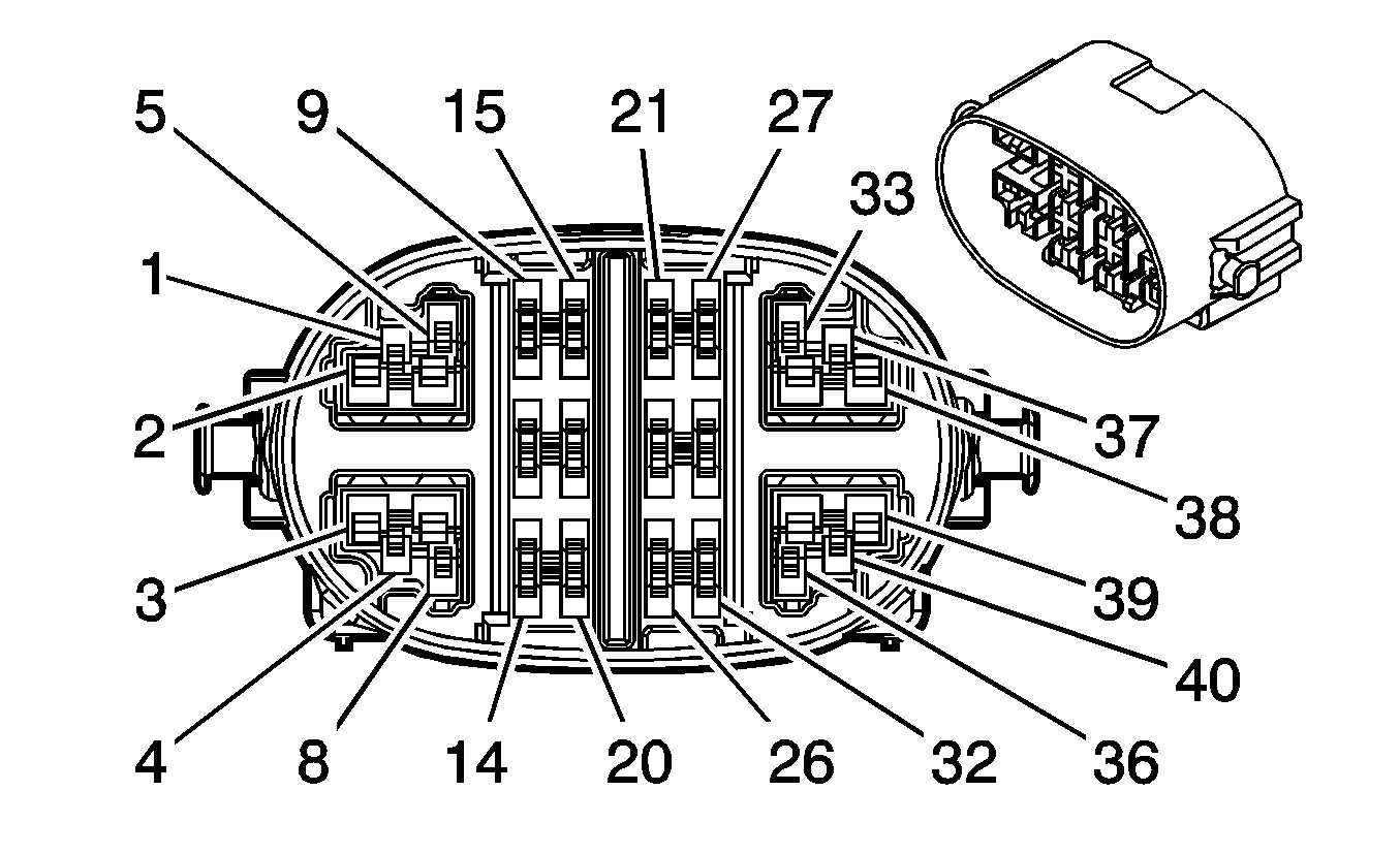
|
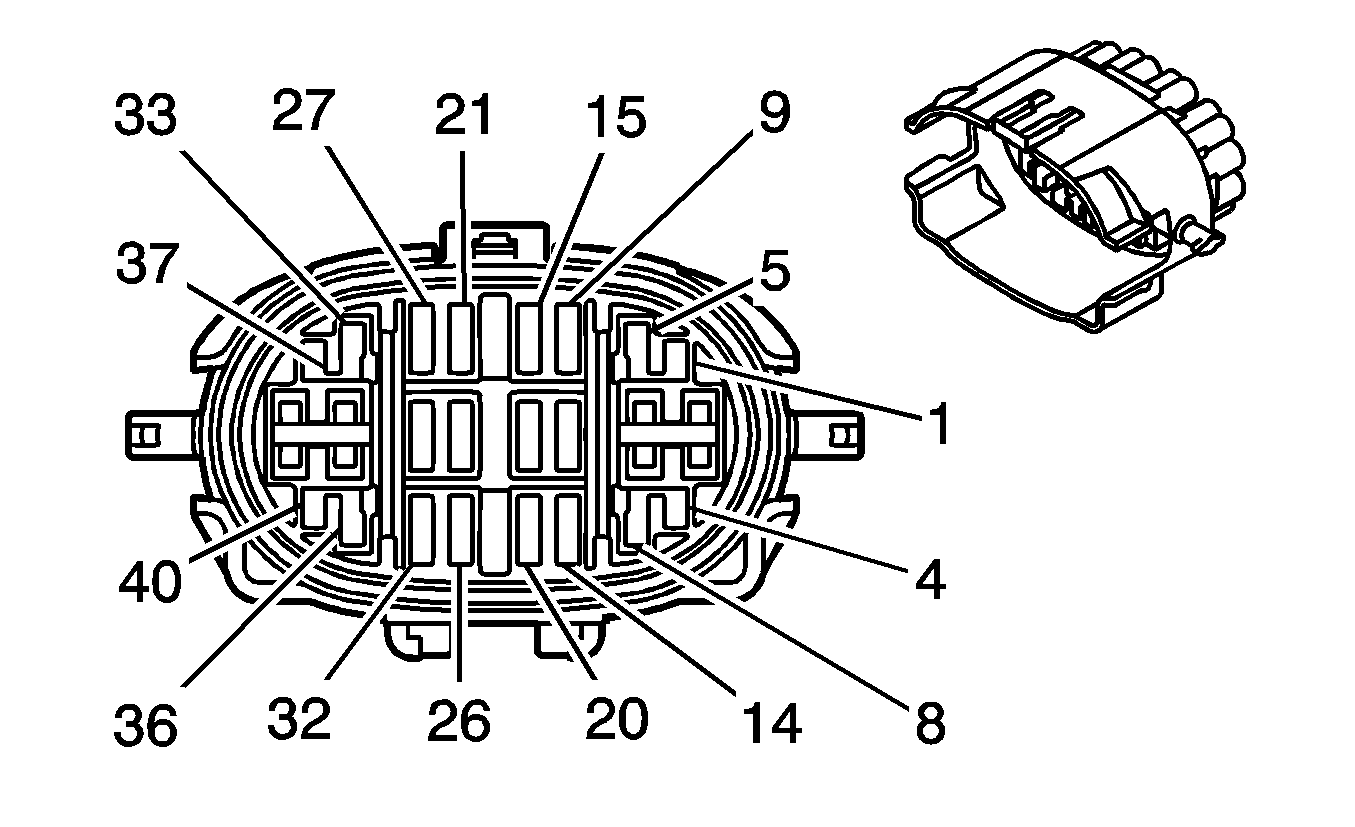
|
Connector Part Information
| Connector Part Information
|
Terminal Part Information
| Terminal Part Information
|
Pin | Wire Color | Circuit No. | Function | Pin | Wire Color | Circuit No. | Function |
|---|---|---|---|---|---|---|---|
1 | 0.5 D-BU | 5930 | Turbocharger Vane Position Control Solenoid Valve Control | 1 | 0.5 D-BU | IC170 | Turbocharger Vane Position Control Solenoid Valve Control |
2 | 1 PK | 5425 | Fuel Injector Supply Voltage 4 | 2 | 2 PK | IC12 | Fuel Injector Supply Voltage 4 |
3 | 1 PU | 5423 | Fuel Injector Supply Voltage 3 | 3 | 2 PU | IC13 | Fuel Injector Supply Voltage 3 |
4 | 0.5 L-BU | 6118 | Air Temperature Sensor Signal | 4 | 0.5 L-BU | IC188 | Air Temperature Sensor Signal |
5 | 0.5 WH | 5931 | Low Reference | 5 | 0.5 WH | IC171 | Low Reference |
6 | 1 PK/BK | 1746 | Fuel Injector 3 Control | 6 | 2 PK/BK | IC17 | Fuel Injector 3 Control |
7 | 1 L-GN/BK | 1745 | Fuel Injector 2 Control | 7 | 2 L-GN/BK | IC16 | Fuel Injector 2 Control |
8 | 0.5 YE/BK | 6120 | Low Reference | 8 | 0.5 YE/BK | IC189 | Low Reference |
9-14 | -- | -- | Not Used | 9-14 | -- | -- | Not Used |
15 | 0.5 PU/WH | 6270 | 5-Volt Reference | 15 | 0.5 PU/WH | IC23 | 5-Volt Reference |
16 | 0.5 GY/BK | 6272 | Low Reference | 16 | 0.5 GY/BK | IC25 | Low Reference |
17 | 0.5 WH/BK | 6271 | CKP Sensor Signal | 17 | 0.5 WH/BK | IC24 | CKP Sensor Signal |
18 | 0.5 L-GN | 432 | MAP Sensor Signal | 18 | 0.5 L-GN | IC94 | MAP Sensor Signal |
19 | 0.5 OG/BK | 469 | Low Reference | 19 | 0.5 OG/BK | IC93 | Low Reference |
20 | 0.5 GY | 2704 | 5-Volt Reference | 20 | 0.5 GY | IC92 | 5-Volt Reference |
21 | 0.5 TN | 2917 | 5-Volt Reference | 21 | 0.5 TN | IC37 | 5-Volt Reference |
22 | 0.5 OG/BK | 2919 | Low Reference | 22 | 0.5 OG/BK | IC46 | Low Reference |
23 | 0.5 YE | 2918 | FRP Sensor Signal | 23 | 0.5 YE | IC40 | FRP Sensor Signal |
24 | 0.5 D-BU/WH | 6265 | CMP Sensor Signal | 24 | 0.5 D-BU/WH | IC27 | CMP Sensor Signal |
25 | 0.5 BN | 6266 | Low Reference | 25 | 0.5 BN | IC28 | Low Reference |
26 | 0.5 D-BU | 6259 | 5-Volt Reference | 26 | 0.5 D-BU | IC26 | 5-Volt Reference |
27 | 0.5 GY/WH | 2705 | 5-Volt Reference | 27 | 0.5 GY | IC57 | 5-Volt Reference |
28 | 0.5 BK | 2755 | Low Reference | 28 | 0.5 BK | IC71 | Low Reference |
29 | 0.5 TN/WH | 331 | Pressure Sensor Signal | 29 | 0.5 TN/WH | IC66 | Pressure Sensor Signal |
30 | 0.5 YE | 5947 | Turbocharger Vase Position Sensor Signal | 30 | 0.5 YE | IC162 | Turbocharger Vase Position Sensor Signal |
31 | 0.5 OG/BK | 5929 | Low Reference | 31 | 0.5 OG/BK | IC161 | Low Reference |
32 | 0.5 TN | 5928 | 5-Volt Reference | 32 | 0.5 TN | IC160 | 5-Volt Reference |
33 | 0.5 TN | 2501 | High Speed GMLAN Serial Data Bus- | 33 | 0.75 TN | HB05 | High Speed GMLAN Serial Data Bus- |
34 | 1 TN/WH | 845 | Fuel Injector 5 Control | 34 | 2 TN/WH | IC19 | Fuel Injector 5 Control |
35 | 1 D-BU/WH | 878 | Fuel Injector 8 Control | 35 | 2 D-BU/WH | IC22 | Fuel Injector 8 Control |
36 | 0.5 TN | 2501 | High Speed GMLAN Serial Data Bus- | 36 | 0.75 TN | HB01 | High Speed GMLAN Serial Data Bus- |
37 | 0.5 TN/BK | 2500 | High Speed GMLAN Serial Data Bus+ | 37 | 0.75 TN/BK | HB06 | High Speed GMLAN Serial Data Bus+ |
38 | 0.5 PK | 2239 | Ignition 1 Voltage | 38 | 0.75 PK | HB02 | Ignition 1 Voltage |
39 | 0.35 D-BU | 5985 | Accessory Wakeup Serial Data | 39 | 1 D-BU | HB04 | Accessory Wakeup Serial Data |
40 | 0.5 TN/BK | 2500 | High Speed GMLAN Serial Data Bus+ | 40 | 0.75 TN/BK | HB20 | High Speed GMLAN Serial Data Bus+ |
X109 Engine Harness (-Diesel) or Engine Chassis Harness (Diesel) to Instrument Panel Harness (NQF/NQH)
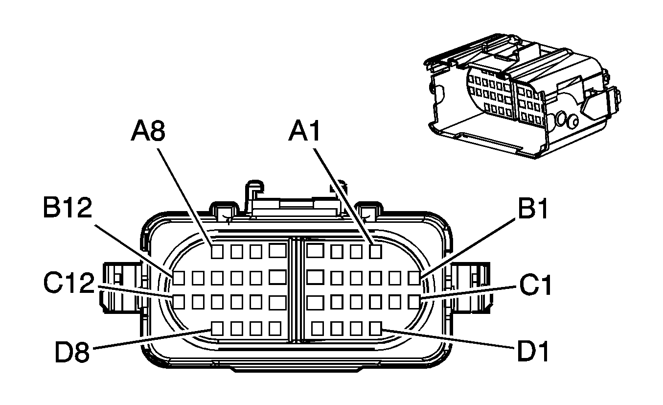
|
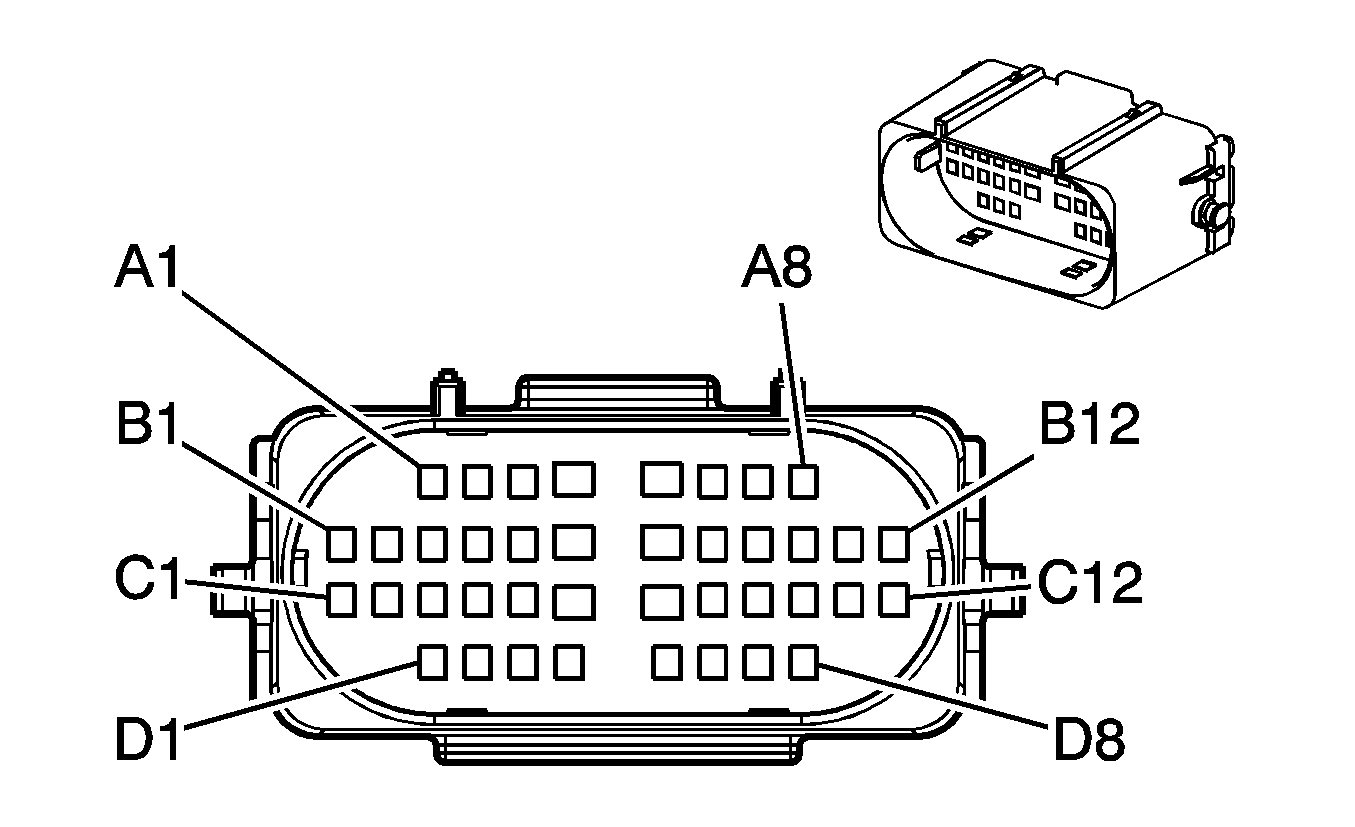
|
Connector Part Information
| Connector Part Information
|
Terminal Part Information
| Terminal Part Information
|
Pin | Wire Color | Circuit No. | Function | Pin | Wire Color | Circuit No. | Function |
|---|---|---|---|---|---|---|---|
A1 | 0.5 OG/WH | 7477 | 5-Volt Reference (NQH) | A1 | 0.5 OG/WH | 7477 | 5-Volt Reference (NQH) |
A2 | 0.35 YE | 7474 | Incremental Encoder Direction Signal | A2 | 0.35 YE | 7474 | Incremental Encoder Direction Signal |
A3 | 0.35 D-BU | 507 | Wait to Start Indicator Control (Diesel) | A3 | 0.35 D-BU | 507 | Wait to Start Indicator Control (Diesel) |
A4 | 3 RD/BK | 1342 | Battery Positive Voltage (NQH) | A4 | 3 RD/BK | 1342 | Battery Positive Voltage (NQH) |
A5 | 3 TN | 1552 | Motor Control A | A5 | 3TN | 1552 | Motor Control A |
A6 | -- | -- | Not Used | A6 | -- | -- | Not Used |
A7 | 0.35 BN/WH | 419 | MIL Control | A7 | 0.35 BN/WH | 419 | MIL Control |
A8 | 0.5 TN/BK | 2500 | High Speed GMLAN Serial Data Bus+ | A8 | 0.5 TN/BK | 2500 | High Speed GMLAN Serial Data Bus+ |
B1 | 0.35 L-GN | 1478 | Coolant Level Switch Signal (Diesel) | B1 | 0.35 L-GN | 1478 | Coolant Level Switch Signal (Diesel) |
B2 | 0.5 PK | 5076 | Current Sensor Supply Voltage (10 Series) | B2 | 0.5 PK | 5076 | Current Sensor Supply Voltage (10 Series) |
B3 | 0.5 WH | 5075 | Current Sensor Signal (10 Series) | B3 | 0.5 WH | 5075 | Current Sensor Signal (10 Series) |
B4 | 0.5 BN | 5077 | Low Reference (10 Series) | B4 | 0.5 BN | 5077 | Low Reference (10 Series) |
B5 | 0.8 BK/WH | 451 | Ground | B5 | 0.5 BK/WH | 451 | Ground |
B6 | 3 OG | 1553 | Motor Control B | B6 | 3 OG | 1553 | Motor Control B |
B7 | 3 BK | 550 | Ground | B7 | 3 BK | 550 | Ground |
B8 | 0.35 D-BU | 5985 | Accessory Wakeup Serial Data | B8 | 0.35 D-BU | 5985 | Accessory Wakeup Serial Data |
B9 | 0.35 WH/GN | 7475 | 8-Volt Reference | B9 | 0.35WH/GN | 7475 | 8-Volt Reference |
B10 | 0.5 TN | 2501 | High Speed GMLAN Serial Data Bus- | B10 | 0.5 TN | 2501 | High Speed GMLAN Serial Data Bus- |
B11 | 0.5 YE/BK | 7478 | Low Reference (NQH) | B11 | 0.5 YE/BK | 7478 | Low Reference (NQH) |
B12 | 0.35 PU | 7476 | Incremental Encoder Sensor Return | B12 | 0.35 PU | 7476 | Incremental Encoder Sensor Return |
C1 | 0.5 PU | 1272 | Low Reference | C1 | 0.35 PU | 1272 | Low Reference |
C2 | 0.5 L-BU | 1162 | APP Sensor 2 Signal | C2 | 0.35 L-BU | 1162 | APP Sensor 2 Signal |
C3 | 0.5 TN | 1274 | 5-Volt Reference | C3 | 0.35 TN | 1274 | 5-Volt Reference |
C4 | 0.5 D-BU | 1161 | APP Sensor 1 Signal | C4 | 0.35 D-BU | 1161 | APP Sensor 1 Signal |
C5 | 0.5 WH/BK | 1164 | 5-Volt Reference | C5 | 0.35 WH/BK | 1164 | 5-Volt Reference |
C6 | 2 TN | 1569 | Lock Solenoid Control (NQH) | C6 | 2 TN | 1569 | Lock Solenoid Control (NQH) |
C7 | 0.5 TN/WH | 1695 | Axle Switch Signal | C7 | 0.5 TN/WH | 1695 | Axle Switch Signal |
C8 | 0.5 GY/BK | 1570 | Axle Actuator - Control | C8 | 0.5 GY/BK | 1570 | Axle Actuator - Control |
C9 | -- | -- | Not Used | C9 | -- | -- | Not Used |
C10 | 0.35 D-BU/WH | 7473 | Incremental Encoder Impulse Signal (NQH) | C10 | 0.35 D-BU/WH | 7473 | Incremental Encoder Impulse Signal |
0.35 L-GN/D-BU | 7473 | Incremental Encoder Impulse Signal (NQF) | |||||
C11 | 0.5 L-GN | 7479 | Rotary Position Sensor Signal (NQH) | C11 | 0.5 L-GN | 7479 | Rotary Position Sensor Signal (NQH) |
C12 | 0.5 D-BU | 204 | A/C Low Pressure Sensor Signal (C67/CJ2) | C12 | 0.5 D-BU | 204 | A/C Low Pressure Sensor Signal (C67/CJ2) |
D1-D6 | -- | -- | Not Used | D1-D6 | -- | -- | Not Used |
D7 | 0.5 BN | 1271 | Low Reference | D7 | 0.35 BN | 1271 | Low Reference |
D8 | -- | -- | Not Used | D8 | -- | -- | Not Used |
X109 Engine Harness (-Diesel) or Engine Chassis Harness (Diesel) to Instrument Panel Harness (-NQF/-NQH)
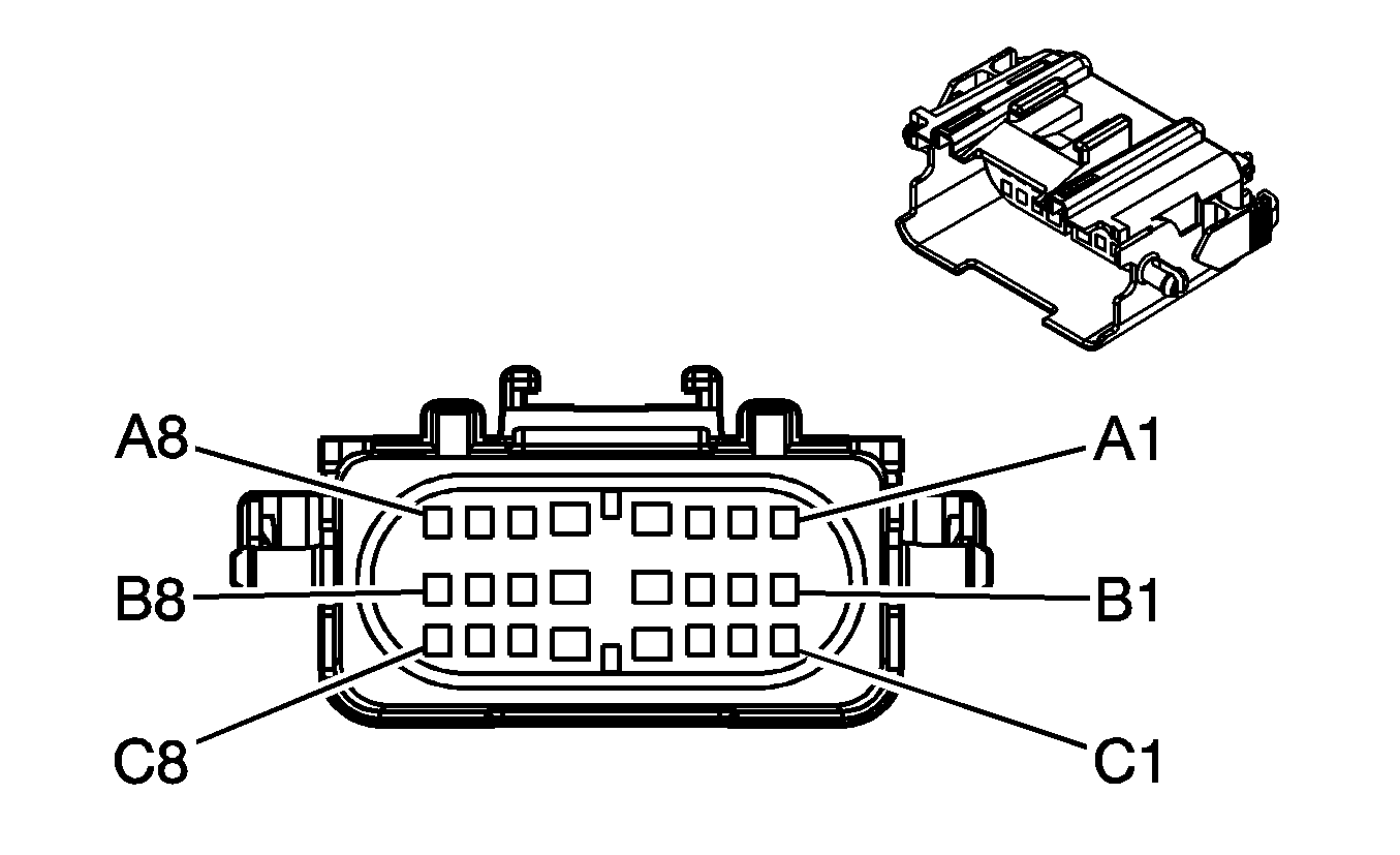
|
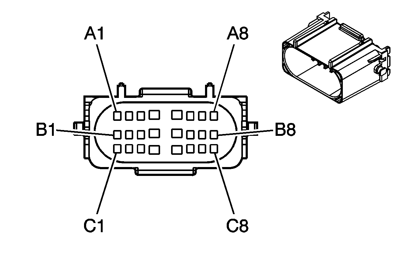
|
Connector Part Information
| Connector Part Information
|
Terminal Part Information
| Terminal Part Information
|
Pin | Wire Color | Circuit No. | Function | Pin | Wire Color | Circuit No. | Function |
|---|---|---|---|---|---|---|---|
A1-A2 | -- | -- | Not Used | A1-A2 | -- | -- | Not Used |
A3 | 0.35 D-BU | 507 | Wait to Start Indicator Control (Diesel) | A3 | 0.35 D-BU | 507 | Wait to Start Indicator Control (Diesel) |
A4-A5 | -- | -- | Not Used | A4-A5 | -- | -- | Not Used |
A6 | 0.5 TN | 2501 | High Speed GMLAN Serial Data Bus- | A6 | 0.5 TN | 2501 | High Speed GMLAN Serial Data Bus- |
A7 | 0.5 BN/WH | 419 | MIL Control | A7 | 0.35 BN/WH | 419 | MIL Control |
A8 | 0.5 TN/BK | 2500 | High Speed GMLAN Serial Data Bus+ | A8 | 0.5 TN/BK | 2500 | High Speed GMLAN Serial Data Bus+ |
B1 | 0.35 L-GN | 1478 | Coolant Level Switch Signal (Diesel) | B1 | 0.35 L-GN | 1478 | Coolant Level Switch Signal (Diesel) |
B2 | 0.5 PK | 5076 | Current Sensor Supply Voltage (10 Series) | B2 | 0.5 PK | 5076 | Current Sensor Supply Voltage (10 Series) |
B3 | 0.5 WH | 5075 | Current Sensor Signal (10 Series) | B3 | 0.5 WH | 5075 | Current Sensor Signal (10 Series) |
B4 | 0.5 BN | 5077 | Low Reference (10 Series) | B4 | 0.5 BN | 5077 | Low Reference (10 Series) |
B5 | 0.8 BK/WH | 451 | Ground | B5 | 0.5 BK/WH | 451 | Ground |
B6 | 0.5 D-BU | 204 | A/C Low Pressure Sensor Signal (C67/CJ2) | B6 | 0.35 D-BU | 204 | A/C Low Pressure Sensor Signal (C67) |
B7 | -- | -- | Not Used | B7 | -- | -- | Not Used |
B8 | 0.35 D-BU | 5985 | Accessory Wakeup Serial Data | B8 | 0.35 D-BU | 5985 | Accessory Wakeup Serial Data |
C1 | 0.5 PU | 1272 | Low Reference | C1 | 0.35 PU | 1272 | Low Reference |
C2 | 0.5 L-BU | 1162 | APP Sensor 2 Signal | C2 | 0.35 L-BU | 1162 | APP Sensor 2 Signal |
C3 | 0.5 TN | 1274 | 5-Volt Reference | C3 | 0.35 TN | 1274 | 5-Volt Reference |
C4 | 0.5 D-BU | 1161 | APP Sensor 1 Signal | C4 | 0.35 D-BU | 1161 | APP Sensor 1 Signal |
C5 | 0.5 WH/BK | 1164 | 5-Volt Reference | C5 | 0.35 WH/BK | 1164 | 5-Volt Reference |
C6 | 0.5 BN | 1271 | Low Reference | C6 | 0.35 BN | 1271 | Low Reference |
C7-C8 | -- | -- | Not Used | C7-C8 | -- | -- | Not Used |
X110 Engine Harness (-Diesel) or Engine Chassis Harness (Diesel) to Front Axle Harness (NQF/NQG/NQH/NP2)
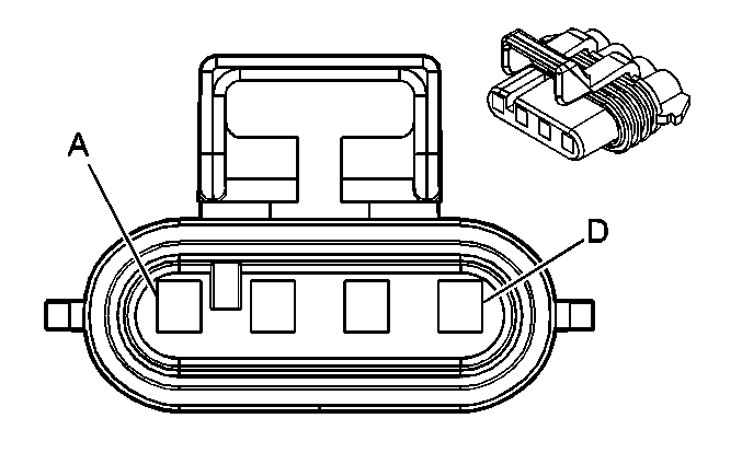
|
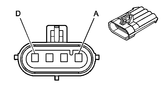
|
Connector Part Information
| Connector Part Information
|
Terminal Part Information
| Terminal Part Information
|
Pin | Wire Color | Circuit No. | Function | Pin | Wire Color | Circuit No. | Function |
|---|---|---|---|---|---|---|---|
A | 0.5 TN/WH | 1695 | Axle Switch Signal | A | 0.5 TN/WH | 1695 | Axle Switch Signal |
B | 0.5 GY/BK | 1570 | Axle Actuator - Control | B | 0.5 GY/BK | 1570 | Axle Actuator - Control |
C | 0.5 PK | 2139 | Ignition 1 Voltage | C | 0.5 PK | 2139 | Ignition 1 Voltage |
D | 0.8 BK | 550 | Ground | D | 0.5 BK | 550 | Ground |
X111 Engine Harness to Left Ignition Coil Harness (4.8L/5.3L/6.0L/6.2L)
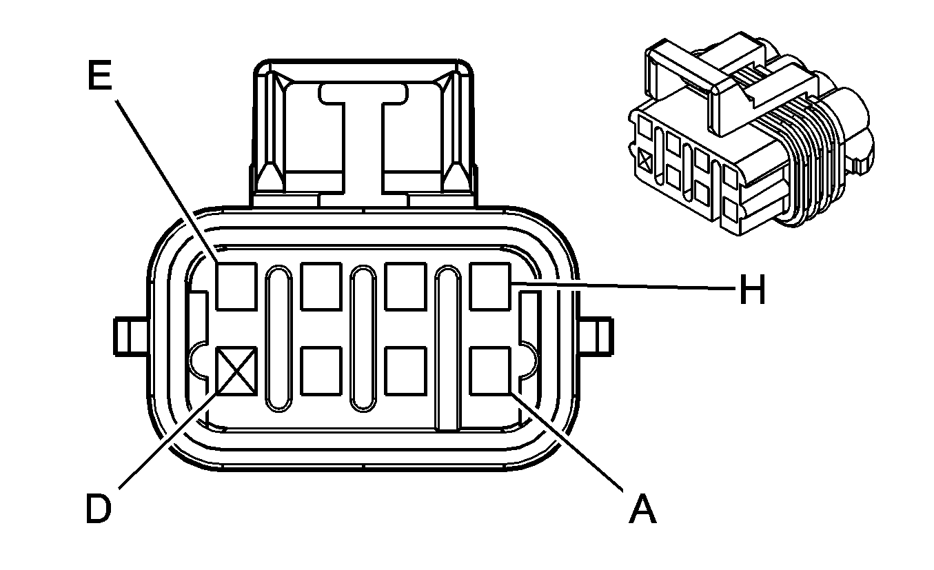
|
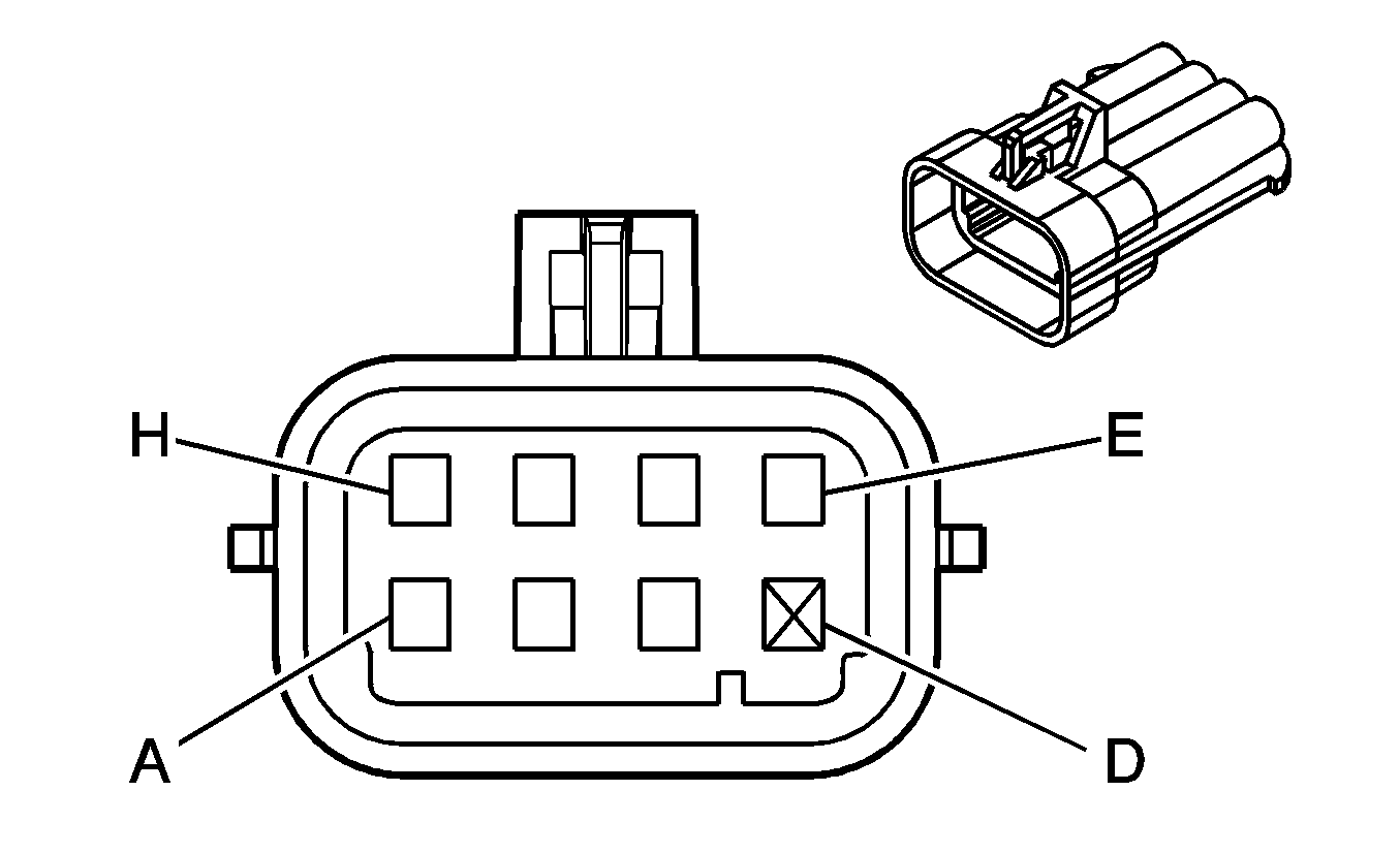
|
Connector Part Information
| Connector Part Information
|
Terminal Part Information
| Terminal Part Information
|
Pin | Wire Color | Circuit No. | Function | Pin | Wire Color | Circuit No. | Function |
|---|---|---|---|---|---|---|---|
A | 1 BK | 350 | Ground | A | 1 BK | 350 | Ground |
B | 0.5 OG | 2127 | IC 7 Control | B | 0.5 RD | 2127 | IC 7 Control |
C | 0.5 D-GN | 2125 | IC 5 Control | C | 0.5 D-GN | 2125 | IC 5 Control |
D | -- | -- | Not Available | D | -- | -- | Not Available |
E | 0.5 BN | 2129 | Low Reference | E | 0.5 BN | 2129 | Low Reference |
F | 0.5 L-BU | 2123 | IC 3 Control | F | 0.5 L-BU | 2123 | IC 3 Control |
G | 0.5 PU | 2121 | IC 1 Control | G | 0.5 PU | 2121 | IC 1 Control |
H | 1 PK | 1039 | Ignition 1 Voltage | H | 1 PK | 1039 | Ignition 1 Voltage |
X112 Engine Harness to Camshaft Position Sensor Jumper Harness (4.3L/4.8L/5.3L)
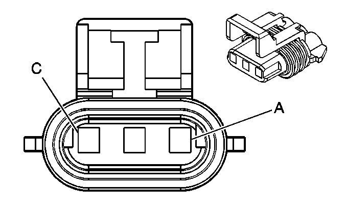
|
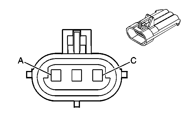
|
Connector Part Information
| Connector Part Information
|
Terminal Part Information
| Terminal Part Information
|
Pin | Wire Color | Circuit No. | Function | Pin | Wire Color | Circuit No. | Function |
|---|---|---|---|---|---|---|---|
A | 0.35 D-BU | 6259 | 5-Volt Reference | A | 0.35 D-BU | 6259 | 5-Volt Reference (4.8L/5.3L) |
0.35 RD | 6259 | 5-Volt Reference (4.3L) | |||||
B | 0.35 BN | 6266 | Low Reference | B | 0.35 BN | 6266 | Low Reference (4.8L/5.3L) |
0.35 PK | 6266 | Low Reference (4.3L) | |||||
C | 0.35 D-BU/WH | 6265 | CMP Sensor Signal | C | 0.35 D-BU/WH | 6265 | CMP Sensor Signal (4.8L/5.3L) |
0.35 TN/WH | 6265 | CMP Sensor Signal (4.3L) |
X112 Engine Harness to Camshaft Position Sensor Jumper Harness (6.0L/6.2L)
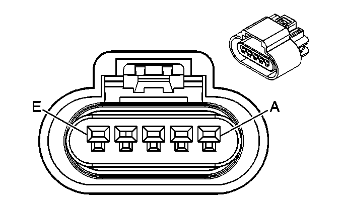
|
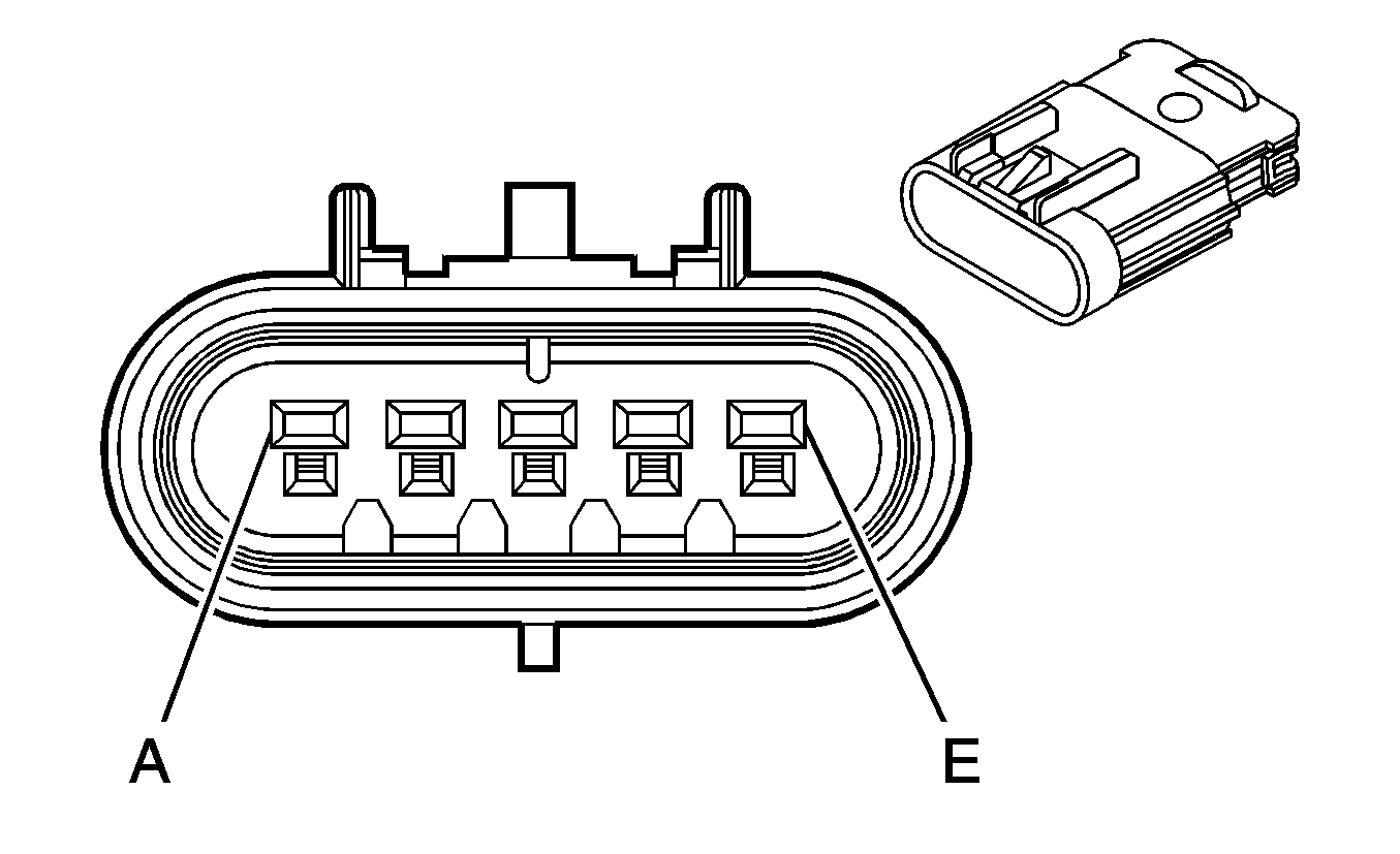
|
Connector Part Information
| Connector Part Information
|
Terminal Part Information
| Terminal Part Information
|
Pin | Wire Color | Circuit No. | Function | Pin | Wire Color | Circuit No. | Function |
|---|---|---|---|---|---|---|---|
A | 0.35 D-BU | 6259 | 5-Volt Reference | A | 0.35 D-BU | 6259 | 5-Volt Reference |
B | 0.35 BN | 6266 | Low Reference | B | 0.35 BN | 6266 | Low Reference |
C | 0.35 D-BU/WH | 6265 | CMP Sensor Signal | C | 0.35 D-BU/WH | 6265 | CMP Sensor Signal |
D | 0.35 PU | 5284 | Camshaft Phaser Intake Solenoid (1) | D | 0.35 TN | 5284 | Camshaft Phaser Intake Solenoid (1) |
E | 0.35 TN | 2199 | Low Reference | E | 0.35 PU | 2199 | Low Reference |
X113 Engine Harness to Right Ignition Coil Harness (4.8L/5.3L/6.0L/6.2L)

|

|
Connector Part Information
| Connector Part Information
|
Terminal Part Information
| Terminal Part Information
|
Pin | Wire Color | Circuit No. | Function | Pin | Wire Color | Circuit No. | Function |
|---|---|---|---|---|---|---|---|
A | 1 BK | 350 | Ground | A | 1 BK | 350 | Ground |
B | 0.5 OG/WH | 2122 | IC 2 Control | B | 0.5 RD | 2122 | IC 2 Control |
C | 0.5 D-GN/WH | 2124 | IC 4 Control | C | 0.5 D-GN | 2124 | IC 4 Control |
D | -- | -- | Not Available | D | -- | -- | Not Available |
E | 0.5 BN/WH | 2130 | Low Reference | E | 0.5 BN | 2130 | Low Reference |
F | 0.5 L-BU/WH | 2126 | IC 6 Control | F | 0.5 L-BU | 2126 | IC 6 Control |
G | 0.5 PU/WH | 2128 | IC 8 Control | G | 0.5 PU | 2128 | IC 8 Control |
H | 1 PK/WH | 1239 | Ignition 1 Voltage | H | 1 PK | 1239 | Ignition 1 Voltage |
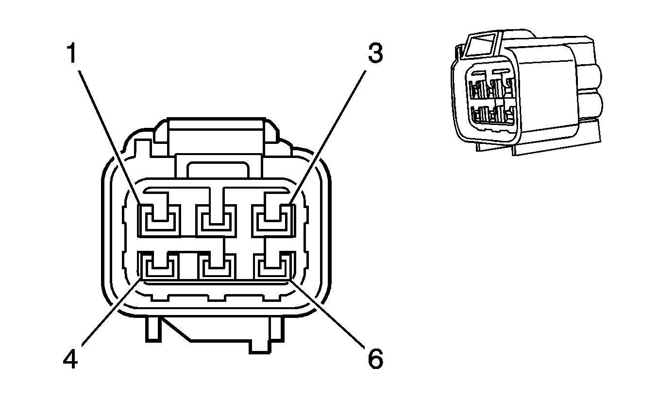
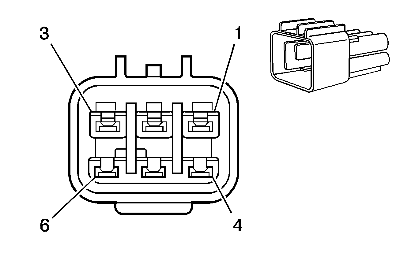
X113 Engine Jumper Harness to Engine Harness (Diesel)
|
|
Connector Part Information
| Connector Part Information
|
Terminal Part Information
| Terminal Part Information
|
Pin | Wire Color | Circuit No. | Function | Pin | Wire Color | Circuit No. | Function |
|---|---|---|---|---|---|---|---|
1 | 0.5 PK/YE | HB03 | Ground | 1 | 0.75 RD | HB03 | Ground |
2 | 0.5 TN/WH | IC66 | Pressure Sensor Signal | 2 | 0.5 TN/WH | IC66 | Pressure Sensor Signal |
3 | 0.5 BN | IC68 | Oil Level Switch Signal | 3 | 0.5 BN | IC68 | Oil Level Switch Signal |
4 | 0.5 GY | IC57 | 5-Volt Reference | 4 | 0.5 GY | IC57 | 5-Volt Reference |
5 | 0.5 BK | IC71 | Low Reference | 5 | 0.5 BK | IC71 | Low Reference |
6 | -- | -- | Not Used | 6 | -- | -- | Not Used |
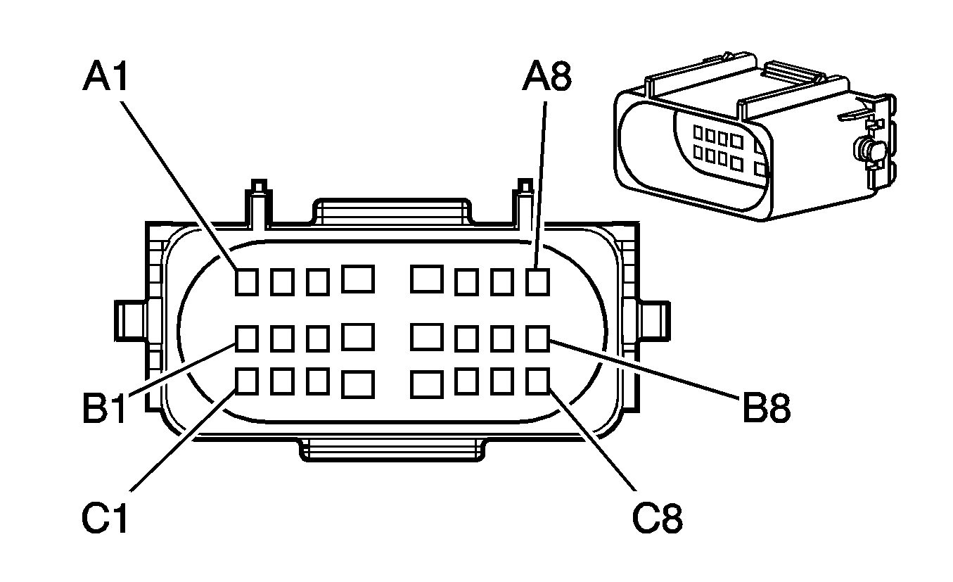
X115 Chassis Harness to Instrument Panel Harness (JL4)

|
|
Connector Part Information
| Connector Part Information
|
Terminal Part Information
| Terminal Part Information
|
Pin | Wire Color | Circuit No. | Function | Pin | Wire Color | Circuit No. | Function |
|---|---|---|---|---|---|---|---|
A1 | 0.5 D-GN | 2087 | Yaw Rate and Lateral Acceleration Sensor Supply Voltage | A1 | 0.5 D-GN | 2087 | Yaw Rate and Lateral Acceleration Sensor Supply Voltage |
A2 | 0.5 YE | 6046 | Steering Angle Sensor Phase A | A2 | 0.35 YE | 6046 | Steering Angle Sensor Phase A |
A3 | 0.5 D-BU | 6047 | Steering Angle Sensor Phase B | A3 | 0.35 D-BU | 6047 | Steering Angle Sensor Phase B |
A4 | 0.5 TN | 6048 | Steering Angle Sensor Phase C | A4 | 0.35 TN | 6048 | Steering Angle Sensor Phase C |
A5 | 0.5 TN/WH | 6433 | CAN Bus High Serial Data | A5 | 0.5 TN/WH | 6433 | CAN Bus High Serial Data |
A6 | 0.5 YE/BK | 2500 | High Speed GMLAN Serial Data Bus+ | A6 | 0.5 TN/BK | 2500 | High Speed GMLAN Serial Data Bus+ |
A7 | 0.5 YE | 2501 | High Speed GMLAN Serial Data Bus- | A7 | 0.5 TN | 2501 | High Speed GMLAN Serial Data Bus- |
A8 | 0.5 L-BU | 5986 | Serial Data Communication Enable | A8 | 0.35 L-BU | 5986 | Serial Data Communication Enable |
B1 | 0.5 PU | 2378 | RR Corner Object Sensor Signal (UD7) | B1 | 0.5 PU | 2378 | RR Corner Object Sensor Signal (UD7) |
B2 | 0.5 D-BU | 2374 | Object Sensor Supply Voltage (UD7) | B2 | 0.5 D-BU | 2374 | Object Sensor Supply Voltage (UD7) |
B3 | -- | -- | Not Used | B2 | -- | -- | Not Used |
B4 | 0.5 L-GN/BK | 6432 | CAN Bus Low Serial Data | B4 | 0.5 L-GN/BK | 6432 | CAN Bus Low Serial Data |
B5 | 3 D-BU | 47 | Trailer Auxiliary Supply Voltage | B5 | 3 D-BU | 47 | Trailer Auxiliary Supply Voltage |
B6 | 0.5 D-GN/WH | 817 | Vehicle Speed Signal | B6 | 0.35 D-GN/WH | 817 | Vehicle Speed Signal |
B7 | 0.5 L-GN | 6043 | Steering Angle Sensor Signal | B7 | 0.35 L-GN | 6043 | Steering Angle Sensor Signal |
B8 | 0.5 GY | 6044 | 5-Volt Reference | B8 | 0.35 GY | 6044 | 5-Volt Reference |
C1 | 0.5 OG/BK | 6045 | Low Reference | C1 | 0.35 OG/BK | 6045 | Low Reference |
C2 | -- | -- | Not Used | C2 | -- | -- | Not Used |
C3 | 0.5 PU/WH | 7333 | Power Brake Booster High Control | C3 | 0.35 PU/WH | 7333 | Power Brake Booster High Control |
C4 | 0.5 TN/BK | 7334 | Power Brake Booster Low Control | C4 | 0.35 TN | 7334 | Power Brake Booster Low Control |
C5 | 0.5 YE | 2375 | LR Corner Object Sensor (UD7) | C5 | 0.5 YE | 2375 | LR Corner Object Sensor Signal (UD7) |
0.35 PK | 7141 | Trailer Connection Signal (Export) | 0.35 PK | 7141 | Trailer Connection Signal (Export) | ||
C6 | 0.5 GY | 2379 | Low Reference (UD7) | C6 | 0.5 GY | 2379 | Low Reference (UD7) |
0.8 L-BU | 1620 | Trailer CHMSL Supply Voltage | 0.8 L-BU | 1620 | Trailer CHMSL Supply Voltage | ||
C7 | 0.5 OG | 2376 | LR Middle Object Sensor Signal (UD7) | C7 | 0.5 OG | 2376 | LR Middle Object Sensor Signal (UD7) |
C8 | 0.5 D-GN | 2377 | RR Middle Object Sensor Signal (UD7) | C8 | 0.5 D-GN | 2377 | RR Middle Object Sensor Signal (UD7) |
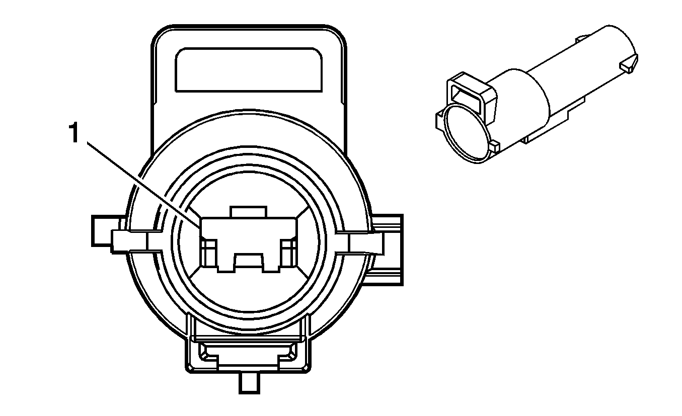
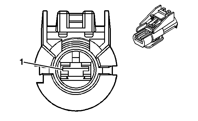
X116 Battery Positive Harness to Brake Clutch Harness (9L4)
|
|
Connector Part Information
| Connector Part Information
|
Terminal Part Information
| Terminal Part Information
|
Pin | Wire Color | Circuit No. | Function | Pin | Wire Color | Circuit No. | Function |
|---|---|---|---|---|---|---|---|
1 | 8 RD/BK | 102 | Battery Positive Voltage | 1 | 8 RD/BK | 102 | Battery Positive Voltage |
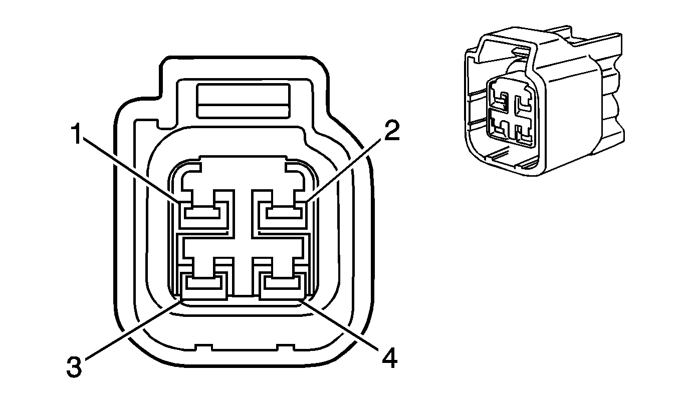
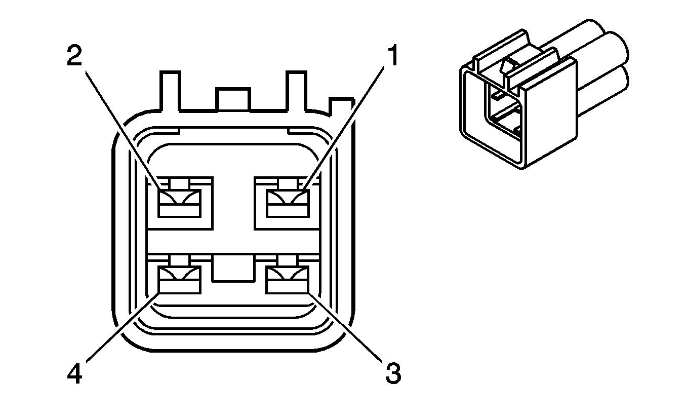
X117 Fuel Rail Pressure Sensor Jumper Harness to Engine Harness (Diesel)
|
|
Connector Part Information
| Connector Part Information
|
Terminal Part Information
| Terminal Part Information
|
Pin | Wire Color | Circuit No. | Function | Pin | Wire Color | Circuit No. | Function |
|---|---|---|---|---|---|---|---|
1 | 0.5 OG/BK | 2919 | Low Reference | 1 | 0.5 OG/BK | IC46 | Low Reference |
2 | 0.5 YE | 2918 | FRP Sensor Signal | 2 | 0.5 YE | IC40 | FRP Sensor Signal |
3 | 0.5 TN | 2917 | 5-Volt Reference | 3 | 0.5 TN | IC37 | 5-Volt Reference |
4 | -- | -- | Not Used | 4 | -- | -- | Not Used |
X121 Battery Negative Harness to Battery Positive Harness (9L4)

|

|
Connector Part Information
| Connector Part Information
|
Terminal Part Information
| Terminal Part Information
|
Pin | Wire Color | Circuit No. | Function | Pin | Wire Color | Circuit No. | Function |
|---|---|---|---|---|---|---|---|
1 | 0.8 BK | 450 | Ground | 1 | 0.8 BK | 450 | Ground |
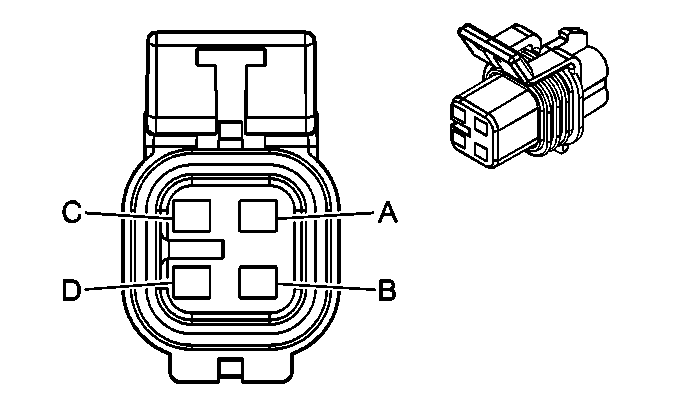
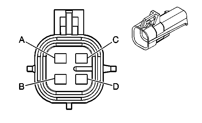
X122 Auxiliary Battery Harness to Engine Harness (TP2)
|
|
Connector Part Information
| Connector Part Information
|
Terminal Part Information
| Terminal Part Information
|
Pin | Wire Color | Circuit No. | Function | Pin | Wire Color | Circuit No. | Function |
|---|---|---|---|---|---|---|---|
A | 0.5 OG | 300 | Ignition 3 Voltage | A | 0.5 OG | 300 | Ignition 3 Voltage |
B | 0.5 BK | 550 | Ground | B | 0.5 BK | 550 | Ground |
C | 0.5 RD/WH | 4540 | Battery Positive Voltage | C | 0.5 RD/WH | 4540 | Battery Positive Voltage |
D | -- | -- | Not Used | D | -- | -- | Not Used |
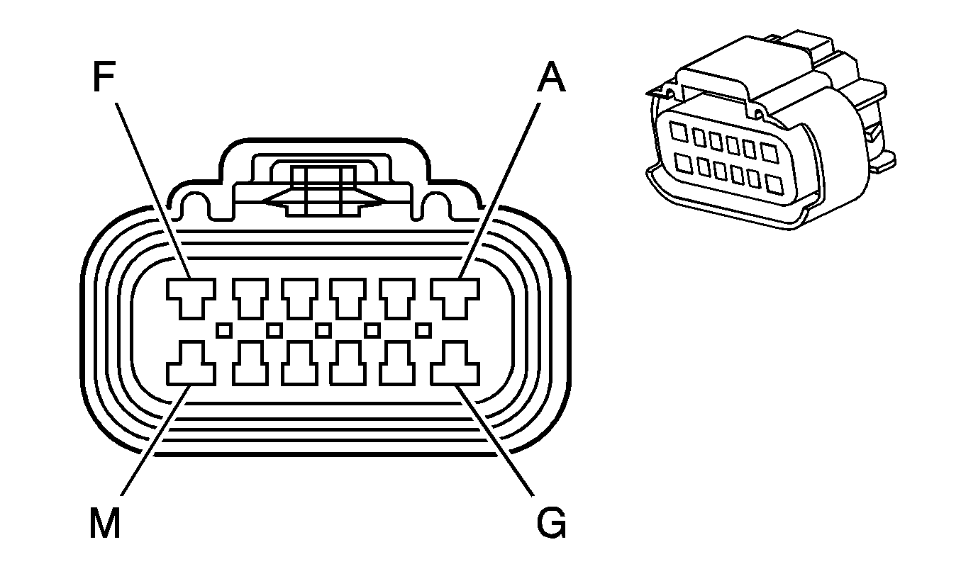
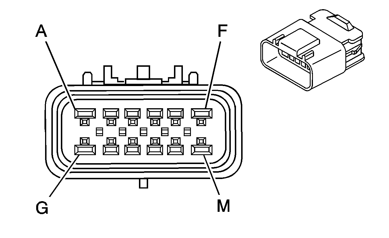
X123 Engine Chassis Harness to Instrument Panel Harness (PTO)
|
|
Connector Part Information
| Connector Part Information
|
Terminal Part Information
| Terminal Part Information
|
Pin | Wire Color | Circuit No. | Function | Pin | Wire Color | Circuit No. | Function |
|---|---|---|---|---|---|---|---|
A | 2 RD/WH | 4540 | Battery Positive Voltage | A | 0.8 RD/WH | 4540 | Battery Positive Voltage |
B | 0.35 L-BU | 5986 | Serial Data Communication Enable | B | 0.35 L-BU | 5986 | Serial Data Communication Enable |
C | 0.8 PK | 239 | Ignition 1 Voltage | C | 0.8 PK | 239 | Ignition 1 Voltage |
D | 0.35 GY/BK | 6086 | Power Take Off Switch Indicator Control | D | 0.35 GY/BK | 6086 | Power Take Off Switch Indicator Control |
E | 0.35 PU | 974 | Low Reference | E | 0.35 PU | 974 | Low Reference |
F | 0.5 RD/WH | 2640 | Battery Positive Voltage | F | 0.5 RD/WH | 2640 | Battery Positive Voltage |
G | -- | -- | Not Used | G | -- | -- | Not Used |
H | 0.35 TN | 973 | Mode Select C | H | 0.35 TN | 973 | Mode Select C |
J | 0.35 D-GN/WH | 972 | Mode Select B | J | 0.35 D-GN/WH | 972 | Mode Select B |
K | 0.35 BN | 971 | Mode Select A | K | 0.35 BN | 971 | Mode Select A |
L | 0.35 YE | 970 | 5-Volt Reference | L | 0.35 YE | 970 | 5-Volt Reference |
M | -- | -- | Not Used | M | -- | -- | Not Used |
X124 Engine Chassis Harness to PTO Jumper Harness (PTO)

|

|
Connector Part Information
| Connector Part Information
|
Terminal Part Information
| Terminal Part Information
|
Pin | Wire Color | Circuit No. | Function | Pin | Wire Color | Circuit No. | Function |
|---|---|---|---|---|---|---|---|
A | 0.8 BN/WH | 6085 | Power Take Off Remote Engine Start Switch Signal | A | 0.8 BN/WH | 6085 | Power Take Off Remote Engine Start Switch Signal |
B | 0.8 L-BU | 494 | Engine Shut Off Signal | B | 0.8 L-BU | 494 | Engine Shut Off Signal |
C | 0.8 GY | 978 | Power Take Off Remote Enable Signal | C | 0.8 GY | 978 | Power Take Off Remote Enable Signal |
D | 0.8 BK | 550 | Ground | D | 0.8 BK | 550 | Ground |
E | 0.35 WH | 975 | 5-Volt Reference | E | 0.35 WH | 975 | 5-Volt Reference |
F | 0.35 D-GN/WH | 6142 | PTO Engine Shutdown Signal | F | 0.35 D-GN/WH | 6142 | PTO Engine Shutdown Signal |
G | 0.8 YE | 2522 | PTO Engage Signal | G | 0.8 YE | 2522 | PTO Engage Signal |
H | 0.35 PU | 2562 | Power Take Off Relay Coil Control | H | 0.35 PU | 2562 | Power Take Off Relay Coil Control |
J | 0.8 BN | 6381 | PTO Relay Engage Signal | J | 0.8 BN | 6381 | PTO Relay Engage Signal |
K | 0.5 RD/WH | 2640 | Battery Positive Voltage | K | 0.8 RD/WH | 2640 | Battery Positive Voltage |
L | 0.35 D-BU/WH | 6089 | Power Take Off Remote Switch Set Signal (1) | L | 0.35 D-BU/WH | 6089 | Power Take Off Remote Switch Set Signal (1) |
M | 0.35 GY/BK | 976 | Low Reference | M | 0.35 GY/BK | 976 | Low Reference |
N | 0.35 L-BU | 977 | PPS Remote Mode | N | 0.35 L-BU | 977 | PPS Remote Mode |
P | 0.8 D-BU | 979 | Remote Start Arming Signal | P | 0.8 D-BU | 979 | Remote Start Arming Signal |
R | 0.8 PK | 239 | Ignition 1 Voltage | R | 0.8 PK | 239 | Ignition 1 Voltage |
S | 0.35 TN | 981 | Torque Limit Request Signal | S | 0.35 TN | 981 | Torque Limit Request Signal |
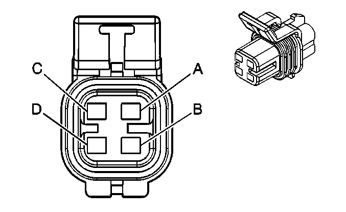
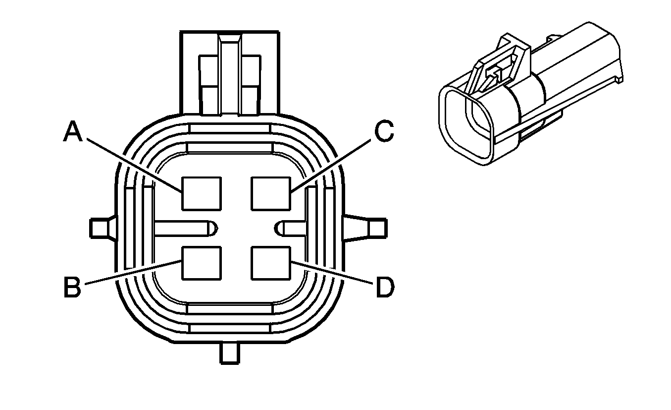
X125 Heated Oxygen Sensor (HO2S) Jumper Harness to Engine Harness (LY6)
|
|
Connector Part Information
| Connector Part Information
|
Terminal Part Information
| Terminal Part Information
|
Pin | Wire Color | Circuit No. | Function | Pin | Wire Color | Circuit No. | Function |
|---|---|---|---|---|---|---|---|
A | 0.5 TN | 1671 | HO2S Low Signal - Bank 2 Sensor 2 | A | 0.8 TN | 1671 | HO2S Low Signal - Bank 2 Sensor 2 |
B | 0.5 PU | 1670 | HO2S High Signal - Bank 2 Sensor 2 | B | 0.8 PU | 1670 | HO2S High Signal - Bank 2 Sensor 2 |
C | 0.5 OG/WH | 3223 | HO2S Heater Low Control - Bank 2 Sensor 2 | C | 0.8 BK | 550 | HO2S Heater Low Control - Bank 2 Sensor 2 |
D | 0.5 PK/BK | 1539 | Ignition 1 Voltage | D | 0.8 PK/BK | 1539 | Ignition 1 Voltage |
X126 Instrument Panel Harness to Chassis Harness (-JL4)

|

|
Connector Part Information
| Connector Part Information
|
Terminal Part Information
| Terminal Part Information
|
Pin | Wire Color | Circuit No. | Function | Pin | Wire Color | Circuit No. | Function |
|---|---|---|---|---|---|---|---|
A | 0.5 TN/BK | 2500 | High Speed GMLAN Serial Data Bus+ | A | 0.5 YE/BK | 2500 | High Speed GMLAN Serial Data Bus+ |
B | 0.5 TN | 2501 | High Speed GMLAN Serial Data Bus- | B | 0.5 YE | 2501 | High Speed GMLAN Serial Data Bus- |
C | 0.35 L-BU | 5986 | Serial Data Communication Enable | C | 0.5 L-BU | 5986 | Serial Data Communication Enable |
D | 0.35 D-GN/WH | 817 | Vehicle Speed Signal | D | 0.5 D-GN/WH | 817 | Vehicle Speed Signal |
E | -- | -- | Not Used | E | -- | -- | Not Used |
F | 0.5 PU | 2378 | RR Corner Object Sensor Signal (UD7) | F | 0.5 PU | 2378 | RR Corner Object Sensor Signal (UD7) |
G | 3 D-BU | 47 | Trailer Auxiliary Supply Voltage (JF3/JF7) | G | 3 D-BU | 47 | Trailer Auxiliary Supply Voltage (JF3/JF7) |
H | 0.5 D-BU | 2374 | Object Sensor Supply Voltage (UD7) | H | 0.5 D-BU | 2374 | Object Sensor Supply Voltage (UD7) |
J | 0.5 YE | 2375 | LR Corner Object Sensor Signal (UD7) | J | 0.5 YE | 2375 | LR Corner Object Sensor Signal (UD7) |
K | 0.5 GY | 2379 | Low Reference (UD7) | K | 0.5 GY | 2379 | Low Reference (UD7) |
L | 0.5 OG | 2376 | LR Middle Object Sensor Signal (UD7) | L | 0.5 OG | 2376 | LR Middle Object Sensor Signal (UD7) |
M | 0.5 D-GN | 2377 | RR Middle Object Sensor Signal (UD7) | M | 0.5 D-GN | 2377 | RR Middle Object Sensor Signal (UD7) |
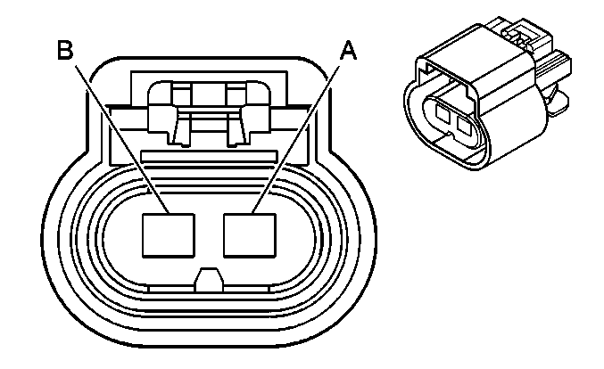
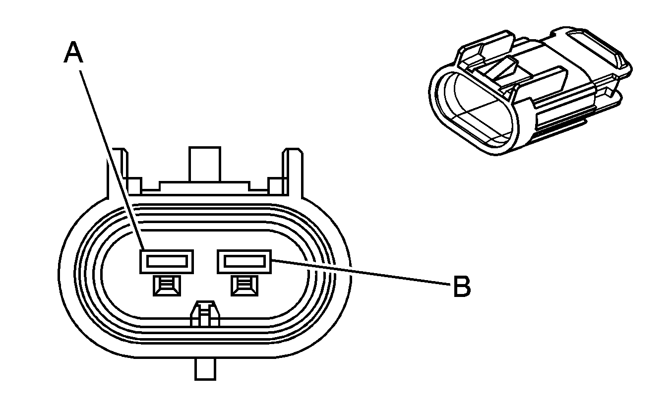
X127 Engine Chassis Harness to Generator Jumper Harness (Diesel)
|
|
Connector Part Information
| Connector Part Information
|
Terminal Part Information
| Terminal Part Information
|
Pin | Wire Color | Circuit No. | Function | Pin | Wire Color | Circuit No. | Function |
|---|---|---|---|---|---|---|---|
A | 0.8 BN | 25 | Charge Indicator Signal | A | 0.8 BN | 25 | Charge Indicator Signal |
B | 0.8 GY | 23 | Generator Field Duty Cycle Signal | B | 0.8 GY | 23 | Generator Field Duty Cycle Signal |
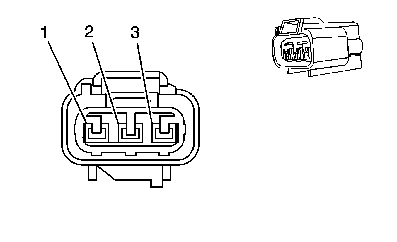
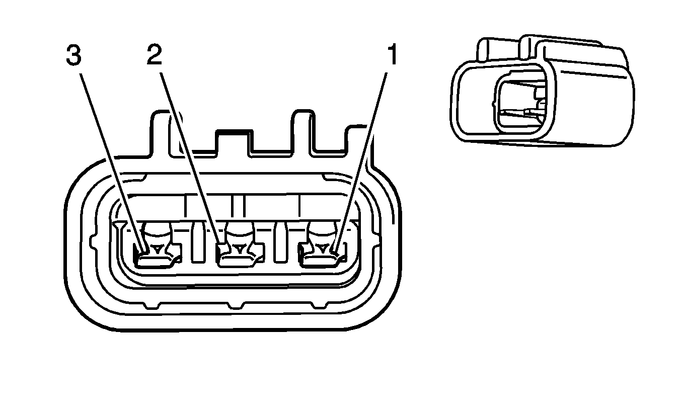
X128 Fuel Pressure Regulator Harness to Engine Harness (Diesel)
|
|
Connector Part Information
| Connector Part Information
|
Terminal Part Information
| Terminal Part Information
|
Pin | Wire Color | Circuit No. | Function | Pin | Wire Color | Circuit No. | Function |
|---|---|---|---|---|---|---|---|
1 | 0.5 PU/WH | 2530 | Fuel Pressure Regulator Solenoid Supply Voltage | 1 | 0.5 PU/WH | IC32 | Fuel Pressure Regulator Solenoid Supply Voltage |
2 | 0.5 YE | 2834 | Fuel Pressure Regulator Solenoid Control | 2 | 0.5 YE | IC31 | Fuel Pressure Regulator Solenoid Control |
3 | 0.5 BK | IZ07 | Ground | 3 | 0.5 BK | IZ07 | Ground |
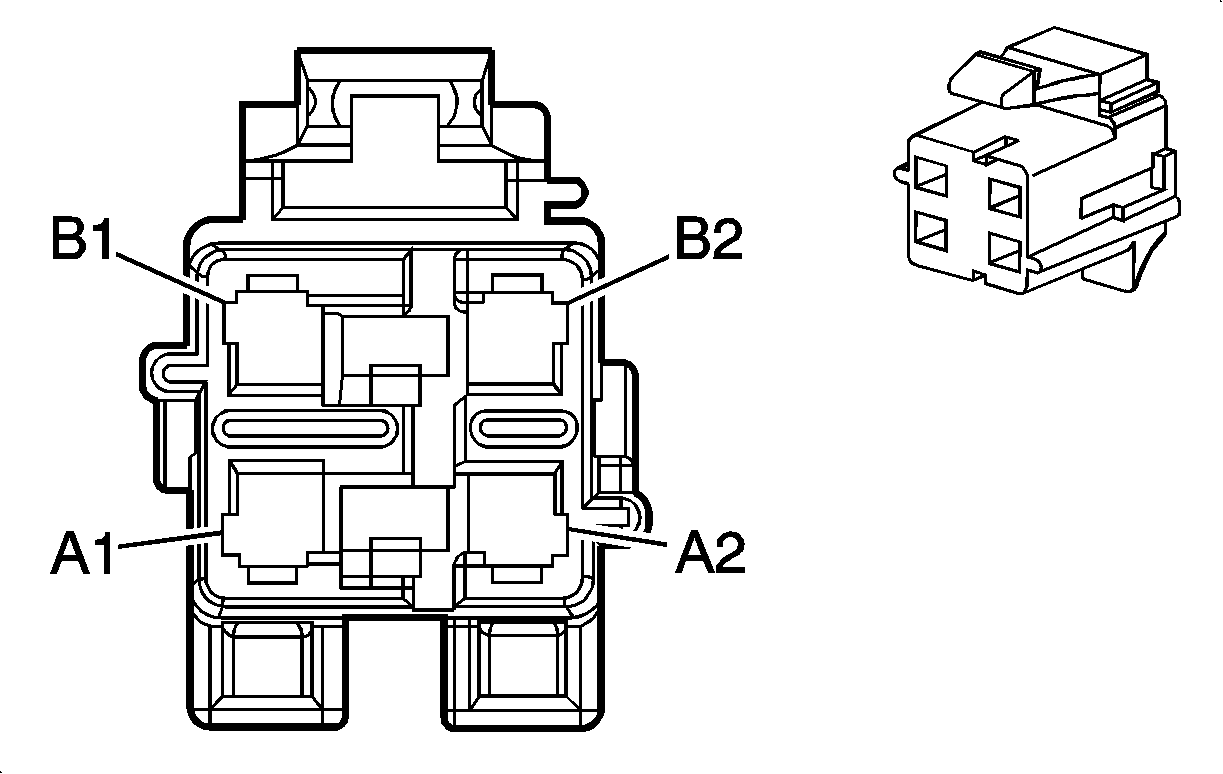
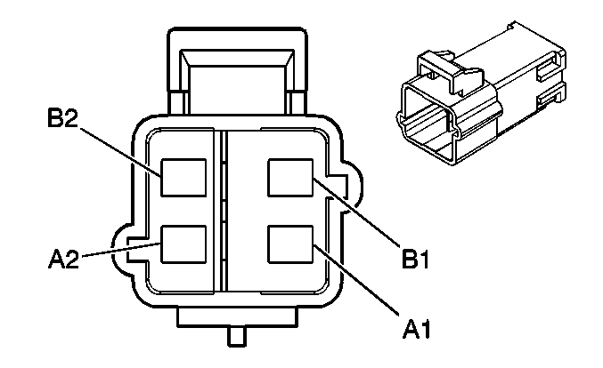
X200 Instrument Panel Harness to Body Harness
|
|
Connector Part Information
| Connector Part Information
|
Terminal Part Information
| Terminal Part Information
|
Pin | Wire Color | Circuit No. | Function | Pin | Wire Color | Circuit No. | Function |
|---|---|---|---|---|---|---|---|
A1 | 0.5 YE | 3025 | I/P Module - Stage 1 - High Control | A1 | 0.5 YE | 3025 | I/P Module - Stage 1 - High Control |
A2 | 0.5 OG | 3024 | I/P Module - Stage 1 - Low Control | A2 | 0.5 OG | 3024 | I/P Module - Stage 1 - Low Control |
B1 | 0.5 GY | 3027 | I/P Module - Stage 2 - High Control (10 Series) | B1 | 0.5 GY | 3027 | I/P Module - Stage 2 - High Control (10 Series) |
B2 | 0.5 PU | 3026 | I/P Module - Stage 2 - Low Control (10 Series) | B2 | 0.5 PU | 3026 | I/P Module - Stage 2 - Low Control (10 Series) |
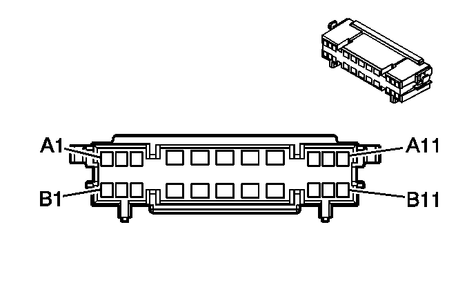
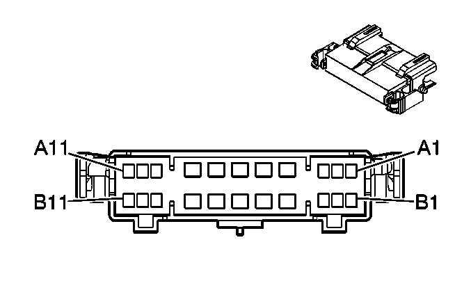
X201 Steering Column Harness to Instrument Panel Harness
|
|
Connector Part Information
| Connector Part Information
|
Terminal Part Information
| Terminal Part Information
|
Pin | Wire Color | Circuit No. | Function | Pin | Wire Color | Circuit No. | Function |
|---|---|---|---|---|---|---|---|
A1 | 0.35 RD/WH | 540 | Battery Positive Voltage | A1 | 0.35 RD/WH | 540 | Battery Positive Voltage |
A2 | 0.35 BN | 6136 | Supply Voltage (K34/KA9/UK3) | A2 | 0.35 BN | 6136 | Supply Voltage |
A3 | 0.35 YE | 6046 | Steering Angle Sensor Phase A (JL4) | A3 | 0.35 YE | 6046 | Steering Angle Sensor Phase A (JL4) |
A4 | -- | -- | Not Used | A4 | -- | -- | Not Used |
A5 | 0.5 BK/WH | 1851 | Ground | A5 | 0.5 BK/WH | 1851 | Ground |
A6 | 0.35 GY | 6044 | 5-Volt Reference (JL4) | A6 | 0.35 GY | 6044 | 5-Volt Reference (JL4) |
A7 | 0.35 L-GN | 6043 | Steering Angle Sensor Signal (JL4) | A7 | 0.35 L-GN | 6043 | Steering Angle Sensor Signal (JL4) |
A8 | 0.35 PK | 94 | Windshield Washer Switch Signal | A8 | 0.35 PK | 94 | Windshield Washer Switch Signal (XA7) |
A9-A10 | -- | -- | Not Used | A9-A10 | -- | -- | Not Used |
A11 | 0.35 OG/BK | 6045 | Low Reference (JL4) | A11 | 0.35 OG/BK | 6045 | Low Reference (JL4) |
B1 | 0.35 TN | 6048 | Steering Angle Sensor Phase C (JL4) | B1 | 0.35 TN | 6048 | Steering Angle Sensor Phase C (JL4) |
B2 | 0.35 D-BU | 6047 | Steering Angle Sensor Phase B (JL4) | B2 | 0.35 D-BU | 6047 | Steering Angle Sensor Phase B (JL4) |
B3 | 0.35 D-GN | 5060 | Low Speed GMLAN Serial Data | B3 | 0.35 D-GN | 5060 | Low Speed GMLAN Serial Data |
B4 | -- | -- | Not Used | B4 | -- | -- | Not Used |
B5 | 0.35 PK | 3 | Ignition Voltage | B5 | -- | -- | Not Used |
0.35 PK | 3 | Ignition Voltage | |||||
B6 | 0.8 BK | 1050 | Ground | B6 | 0.5 BK | 1050 | Ground |
B7 | 0.35 TN | 28 | Horn Relay Control | B7 | 0.35 TN | 28 | Horn Relay Control |
0.35 TN | 28 | Horn Relay Control | |||||
B8 | 0.8 PK | 1639 | Ignition 1 Voltage (KA9) | B8 | 0.35 PK | 1639 | Ignition 1 Voltage (KA9) |
B9 | -- | -- | Not Used | B9 | -- | -- | Not Used |
B10 | 0.35 GN/WH | 7158 | Cruise Control Indicator Dimming Signal (K34/KA9) | B10 | 0.35 L-GN/WH | 7158 | Cruise Control Indicator Dimming Signal |
B11 | -- | -- | Not Used | B11 | -- | -- | Not Used |
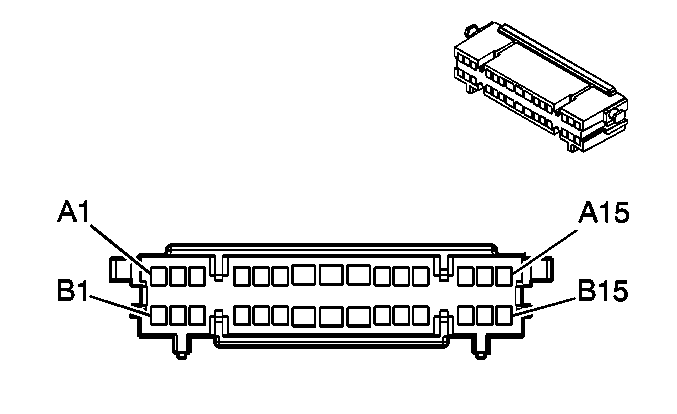
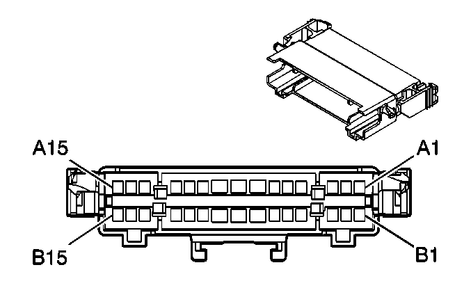
X202 Instrument Panel Harness to Body Harness
|
|
Connector Part Information
| Connector Part Information
|
Terminal Part Information
| Terminal Part Information
|
Pin | Wire Color | Circuit No. | Function | Pin | Wire Color | Circuit No. | Function |
|---|---|---|---|---|---|---|---|
A1 | 0.5 YE | 116 | Left Rear Speaker Output (-) (-Y91) | A1 | 0.8 YE | 116 | Left Rear Speaker Output (-) (-Y91) |
A2 | 0.5 BN | 199 | Left Rear Speaker Output (+) (-Y91) | A2 | 0.8 BN | 199 | Left Rear Speaker Output (+) (-Y91) |
A3 | 0.5 L-BU | 115 | Right Rear Speaker Output (-) (-Y91) | A3 | 0.8 L-BU | 115 | Right Rear Speaker Output (-) (-Y91) |
A4 | 0.5 D-BU | 46 | Right Rear Speaker Output (+) (-Y91) | A4 | 0.8 D-BU | 46 | Right Rear Speaker Output (+) (-Y91) |
A5 | 0.5 L-GN/BK | 6432 | CAN Bus Low Serial Data (JL4) | A5 | 0.5 L-GN/BK | 6432 | CAN Bus Low Serial Data (JL4) |
A6 | 0.5 TN/WH | 6433 | CAN Bus High Serial Data (JL4) | A6 | 0.5 TN/WH | 6433 | CAN Bus High Serial Data (JL4) |
A7 | 0.35 L-BU | 244 | Passenger Door Lock Switch Lock Signal (AU3 -YE9) | A7 | 0.35 L-BU | 244 | Passenger Door Lock Switch Lock Signal (-YE9) |
A8 | 0.35 L-BU | 1134 | Park Brake Switch Signal | A8 | 0.35 L-BU | 1134 | Park Brake Switch Signal |
A9 | 0.5 OG | 2267 | Mirror Heating Element Supply Voltage (DL8/DPN -AN3/DL3) | A9 | 0.5 OG | 2267 | Mirror Heating Element Supply Voltage (DL8/DPN -AN3/DL3) |
0.5 OG | 2267 | Mirror Heating Element Supply Voltage (DL8/DPN -AN3/DL3) | |||||
A10 | 0.35 OG | 5922 | Non-Driver Door Open Switch Signal (-AN3/DL3) | A10 | 0.35 OG | 5922 | Non-Driver Door Open Switch Signal (-AN3/DL3) |
A11 | 0.35 D-GN | 5060 | Low Speed GMLAN Serial Data | A11 | 0.35 D-GN | 5060 | Low Speed GMLAN Serial Data |
A12 | 0.5 D-GN | 2087 | Yaw Rate and Lateral Acceleration Sensor Supply Voltage (JL4) | A12 | 0.5 D-GN | 2087 | Yaw Rate and Lateral Acceleration Sensor Supply Voltage (JL4) |
A13 | 0.35 D-BU | 245 | Passenger Door Lock Switch Unlock Signal (AU3 -YE9) | A13 | 0.35 D-BU | 245 | Passenger Door Lock Switch Unlock Signal (-YE9) |
A14 | 0.35 BN | 5852 | Rear Park Assist LED Disable Signal (YE9/Y91) | A14 | 0.35 BN | 5852 | Rear Park Assist LED Disable Signal (UD7) |
A15 | 0.5 TN/BK | 371 | I/P Module Disable Switch - Signal (C99) | A15 | 0.5 TN/BK | 371 | I/P Module Disable Switch - Signal (C99) |
B1 | 0.5 PK | 353 | I/P Module Suppression Indicator Control (C99) | B1 | 0.5 PK | 353 | I/P Module Suppression Indicator Control (C99) |
B2 | 0.5 YE | 354 | Left Front Discriminating Sensor Signal | B2 | 0.5 YE | 354 | Left Front Discriminating Sensor Signal |
B3 | 0.5 TN/OG | 5045 | Left Front Discriminating Sensor Signal | B3 | 0.5 TN/OG | 5045 | Left Front Discriminating Sensor Signal |
B4 | 0.5 GY | 5600 | Low Reference (10 Series) | B4 | 0.5 GY | 5600 | Low Reference (10 Series) |
B5 | 0.5 D-GN | 1409 | Right Front Discriminating Sensor Signal (10 Series) | B5 | 0.5 D-GN | 1409 | Right Front Discriminating Sensor Signal (10 Series) |
B6 | 0.35 GY | 2555 | Rear Park Assist Disable Signal (YE9/Y91) | B6 | 0.35 GY | 2555 | Rear Park Assist Disable Signal (UD7) |
B7 | 0.35 TN/WH | 746 | Right Front Door Ajar Switch Signal (-AN3/DL3) | B7 | 0.35 TN/WH | 746 | Right Front Door Ajar Switch Signal (-AN3/DL3) |
B8 | 3 PU | 293 | Rear Defog Element Supply Voltage (C49) | B8 | 3 PU | 293 | Rear Defog Element Supply Voltage (C49) |
B9 | 0.35 YE | 43 | Accessory Voltage (YE9 -AN3/DL3) | B9 | 0.35 YE | 43 | Accessory Voltage (YE9 -AN3/DL3) |
B10 | 0.5 PU | 2378 | RR Corner Object Sensor Signal (UD7) | B10 | 0.5 PU | 2378 | RR Corner Object Sensor Signal (UD7) |
B11 | 0.5 D-BU | 2374 | Object Sensor Supply Voltage (UD7) | B11 | 0.5 D-BU | 2374 | Object Sensor Supply Voltage (UD7) |
B12 | 0.5 YE | 2375 | LR Corner Object Sensor Signal (UD7) | B12 | 0.5 YE | 2375 | LR Corner Object Sensor Signal (UD7) |
B13 | 0.5 GY | 2379 | Low Reference (UD7) | B13 | 0.5 GY | 2379 | Low Reference (UD7) |
B14 | 0.5 OG | 2376 | LR Middle Object Sensor Signal (UD7) | B14 | 0.5 OG | 2376 | LR Middle Object Sensor Signal (UD7) |
B15 | 0.5 D-GN | 2377 | RR Middle Object Sensor Signal (UD7) | B15 | 0.5 D-GN | 2377 | RR Middle Object Sensor Signal (UD7) |
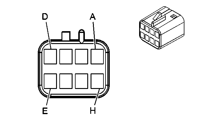
X203 Instrument Panel Harness (Y91) or I/P Extension Harness (-Y91) to Headliner Harness (UE1/U3U/UVB)
|
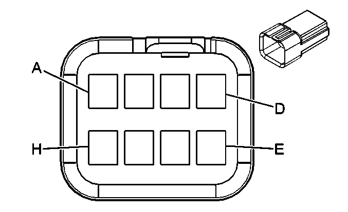
|
Connector Part Information
| Connector Part Information
|
Terminal Part Information
| Terminal Part Information
|
Pin | Wire Color | Circuit No. | Function | Pin | Wire Color | Circuit No. | Function |
|---|---|---|---|---|---|---|---|
A | 0.35 YE/BK | 2516 | Keypad Green LED Signal (UE1) | A | 0.35 YE/BK | 2516 | Keypad Green LED Signal (UE1) |
B | 0.35 BN/WH | 2517 | Keypad Red LED Signal (UE1) | B | 0.35 BN/WH | 2517 | Keypad Red LED Signal (UE1) |
C | 0.35 L-GN/BK | 2515 | Keypad Supply Voltage (UE1) | C | 0.35 L-GN/BK | 2515 | Keypad Supply Voltage (UE1) |
D | 0.35 D-GN/WH | 2514 | Keypad Signal (UE1) | D | 0.35 D-GN/WH | 2514 | Keypad Signal (UE1) |
E | -- | -- | Not Used | E | -- | -- | Not Used |
F | 0.35 GY | 655 | Cellular Telephone Voice Signal (UE1/U3U/UVB) | F | 0.35 GY | 655 | Cellular Telephone Voice Signal (UE1/U3U/UVB) |
G | 0.5 BARE | 514 | Drain Wire (UE1/U3U/UVB) | G | 0.5 BARE | 514 | Drain Wire (UE1/U3U/UVB) |
H | -- | -- | Not Used | H | -- | -- | Not Used |
X204 Headliner Harness to Instrument Panel Harness (Y91) or I/P Extension Harness (-Y91) (+U42)
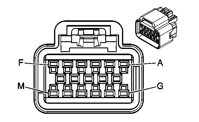
|
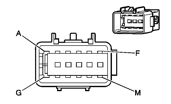
|
Connector Part Information
| Connector Part Information
|
Terminal Part Information
| Terminal Part Information
|
Pin | Wire Color | Circuit No. | Function | Pin | Wire Color | Circuit No. | Function |
|---|---|---|---|---|---|---|---|
A | 0.35 PK | 5829 | Infra Red Module Supply Voltage | A | 0.35 PK | 5829 | Infra Red Module Supply Voltage |
B | 0.35 OG/BK | 5329 | Left Infra Red Audio Signal | B | 0.35 OG/BK | 5329 | Left Infra Red Audio Signal |
C | 0.35 PU/WH | 5330 | Right Infra Red Audio Signal | C | 0.35 PU/WH | 5330 | Right Infra Red Audio Signal |
D | 0.35 BN/WH | 5331 | Infra Red Audio Low Reference | D | 0.35 BN/WH | 5331 | Infra Red Audio Low Reference |
E | 0.35 BARE | 5332 | Infra Red Audio Drain Wire | E | 0.35 BARE | 5332 | Infra Red Audio Drain Wire (Y91) |
0.5 BARE | 5332 | Infra Red Audio Drain Wire (-Y91) | |||||
F | 0.35 L-BU | 5826 | Left DVD Audio Signal (+) | F | 0.35 L-BU | 5826 | Left DVD Audio Signal (+) |
G | 0.35 WH | 5828 | Right DVD Audio Signal (+) | G | 0.35 WH | 5828 | Right DVD Audio Signal (+) |
H | 0.35 PU | 6979 | DVD Audio Common | H | 0.35 PU | 6979 | DVD Audio Common |
J | 0.35 BARE | 6980 | DVD Audio Shield | J | 0.35 BARE | 6980 | DVD Audio Shield (Y91) |
0.5 BARE | 6980 | DVD Audio Shield (-Y91) | |||||
K | 0.35 OG/BK | 5831 | Remote Infra Red Signal (+) | K | 0.35 OG/BK | 5831 | Remote Infra Red Signal (+) |
L | 0.35 TN/WH | 5830 | Remote Infra Red Signal (-) | L | 0.35 TN/WH | 5830 | Remote Infra Red Signal (-) |
M | 0.35 BK | 2550 | Ground | M | 0.35 BK | 2550 | Ground |
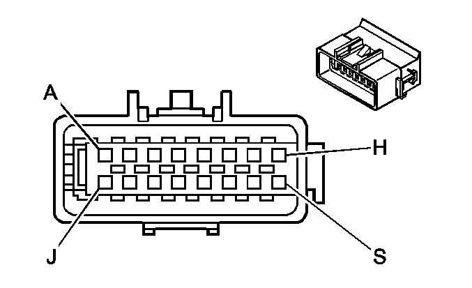
X205 Brake Clutch Harness to Instrument Panel Harness
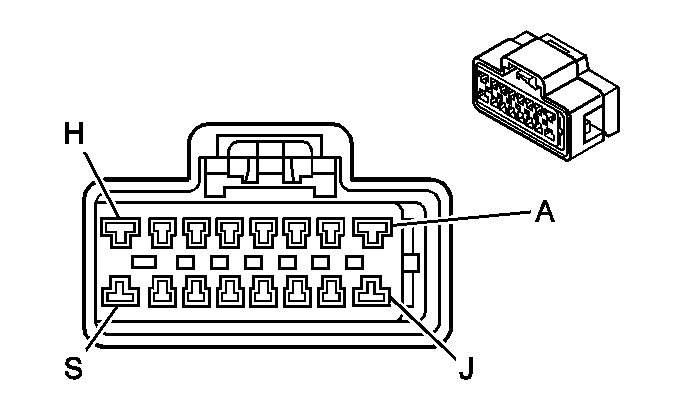
|
|
Connector Part Information
| Connector Part Information
|
Terminal Part Information
| Terminal Part Information
|
Pin | Wire Color | Circuit No. | Function | Pin | Wire Color | Circuit No. | Function |
|---|---|---|---|---|---|---|---|
A | 0.35 L-BU/WH | 6311 | TCC Brake Signal | A | 0.35 L-BU/WH | 6311 | TCC Brake Signal |
0.35 L-BU/WH | 6311 | TCC Brake Signal (JL1) | |||||
B | 0.35 L-BU | 1162 | APP Sensor 2 Signal | B | 0.35 L-BU | 1162 | APP Sensor 2 Signal |
C | 0.35 TN | 1274 | 5-Volt Reference | C | 0.35 TN | 1274 | 5-Volt Reference |
D | 0.35 D-BU | 1161 | APP Sensor 1 Signal | D | 0.35 D-BU | 1161 | APP Sensor 1 Signal |
E | 0.35 PU | 1272 | Low Reference | E | 0.35 PU | 1272 | Low Reference |
F | -- | -- | Not Used | F | -- | -- | Not Used |
G | 0.35 YE | 6817 | LED Backlight Dimming Control (JL1) | G | 0.35 YE | 6817 | LED Backlight Dimming Control (JL1) |
H | 0.35 OG/WH | 812 | 12-Volt Reference | H | 0.35 OG/WH | 812 | 12-Volt Reference |
0.35 OG/WH | 812 | 12-Volt Reference | |||||
J | 0.35 PK | 239 | Ignition 1 Voltage | J | 0.35 PK | 239 | Ignition 1 Voltage |
0.35 PK | 239 | Ignition 1 Voltage (JL1) | |||||
K | 0.35 PU | 7062 | Brake Switch Signal | K | 0.35 PU | 7062 | Brake Switch Signal |
L | 0.35 WH/BK | 1164 | 5-Volt Reference | L | 0.35 WH/BK | 1164 | 5-Volt Reference |
M | 0.35 BN | 1271 | Low Reference | M | 0.35 BN | 1271 | Low Reference |
N-P | -- | -- | Not Used | N-P | -- | -- | Not Used |
S | 0.35 WH | 5990 | Emergency Lamp Switch Signal (5X7/5Y0) | S | 0.35 WH | 5990 | Emergency Lamp Switch Signal (5X7/5Y0) |
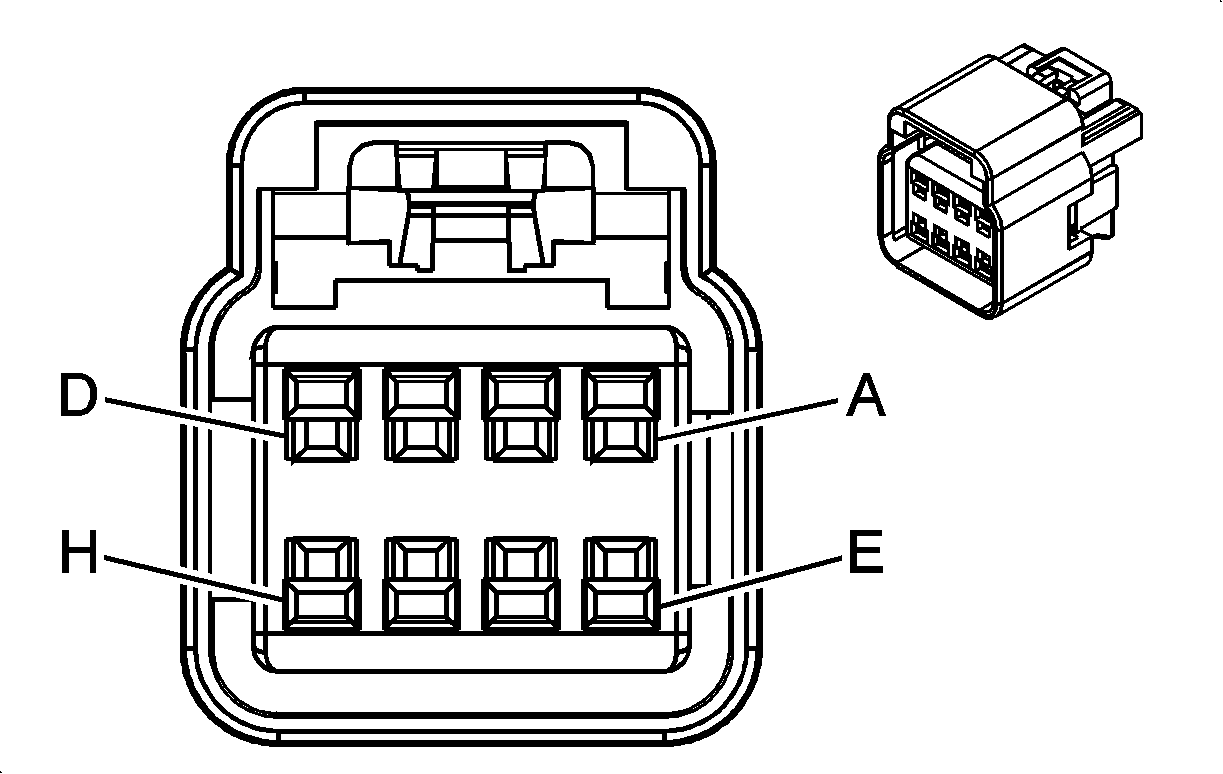
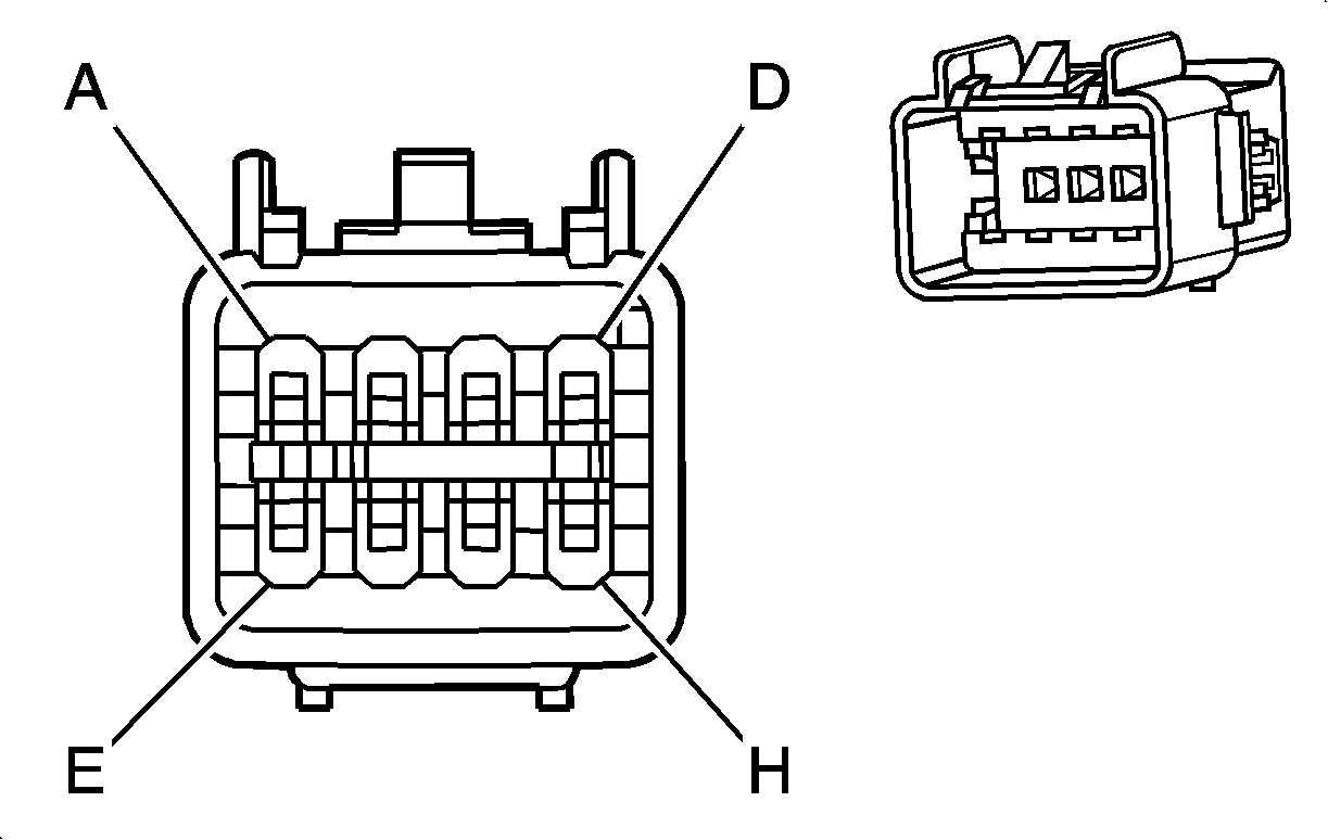
X206 Right A-Pillar Harness to Instrument Panel Harness (Y91) or I/P Extension Harness (-Y91) (U42)
|
|
Connector Part Information
| Connector Part Information
|
Terminal Part Information
| Terminal Part Information
|
Pin | Wire Color | Circuit No. | Function | Pin | Wire Color | Circuit No. | Function |
|---|---|---|---|---|---|---|---|
A | 0.35 PK/BK | 5844 | Video Bright Control | A | 0.35 PK/BK | 5844 | Video Bright Control |
B | 0.35 WH/BK | 5335 | DVD Video Signal (-) | B | 0.35 WH/BK | 5335 | DVD Video Signal (-) |
C | 0.35 BARE | 6976 | Drain Wire | C | 0.35 BARE | 6976 | Drain Wire (Y91) |
0.35 BARE | 6976 | Drain Wire (-Y91) | |||||
D | 0.35 D-GN | 6975 | DVD Video Signal (+) | D | 0.35 D-GN | 6975 | DVD Video Signal (+) |
E | 0.35 L-GN/BK | 5845 | Video Module Signal | E | 0.35 L-GN/BK | 5845 | Video Module Signal |
F | 0.5 RD/WH | 3240 | Battery Positive Voltage | F | 0.5 RD/WH | 3240 | Battery Positive Voltage |
G | 0.5 BK | 2550 | Ground | G | 0.5 BK | 2550 | Ground |
H | 0.35 WH | 7066 | Entertainment Remote Enable Signal | H | 0.35 WH | 7066 | Entertainment Remote Enable Signal |
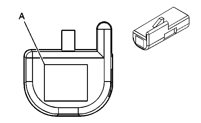
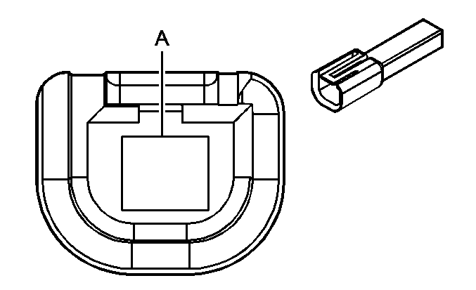
X207 I/P Harness to I/P Harness (6J4)
|
|
Connector Part Information
| Connector Part Information
|
Terminal Part Information
| Terminal Part Information
|
Pin | Wire Color | Circuit No. | Function | Pin | Wire Color | Circuit No. | Function |
|---|---|---|---|---|---|---|---|
A | 0.35 TN | 28 | Horn Relay Control | A | 0.35 TN | 28 | Horn Relay Control |
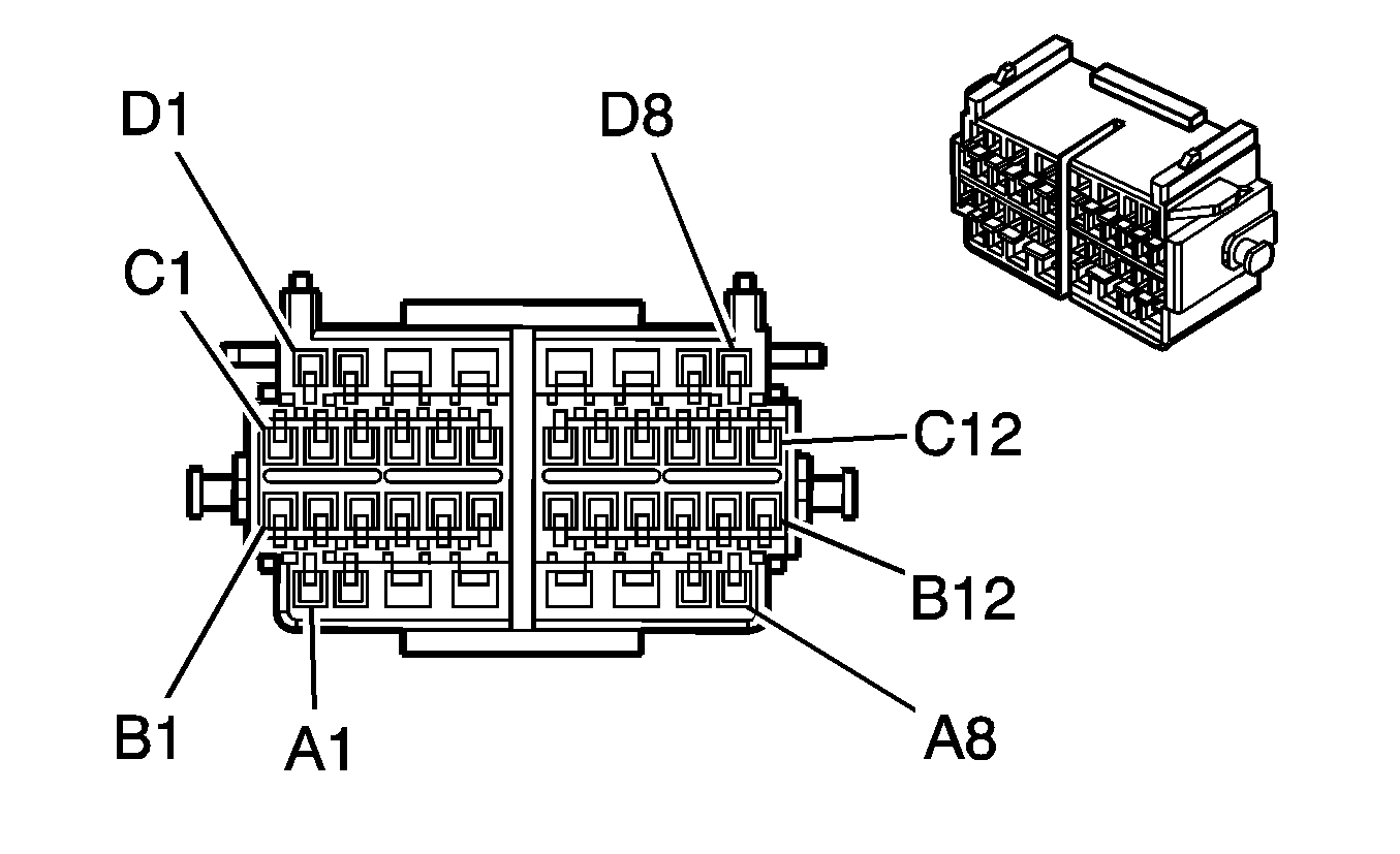
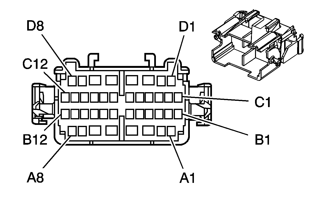
X211 Instrument Panel Harness (Y91) or I/P Extension Harness (-Y91) to Console Harness (Y91/UQA/D07)
|
|
Connector Part Information
| Connector Part Information
|
Terminal Part Information
| Terminal Part Information
|
Pin | Wire Color | Circuit No. | Function | Pin | Wire Color | Circuit No. | Function |
|---|---|---|---|---|---|---|---|
A1 | 0.35 OG/BK | 5329 | Left Infra Red Audio Signal (U42) | A1 | 0.35 OG/BK | 5329 | Left Infra Red Audio Signal (U42) |
A2 | 0.35 OG | 6978 | Amplifier Control (UQA -Y91) | A2 | 0.35 OG | 6978 | Amplifier Control (UQA -Y91) |
0.8 YE/BK | 1860 | Front Center Speaker Output (+) (Y91) | 0.8 YE/BK | 1860 | Front Center Speaker Output (+) (Y91) | ||
A3 | 0.35 WH | 7066 | Entertainment Remote Enable Signal (UQA -Y91) | A3 | 0.35 WH | 7066 | Entertainment Remote Enable Signal (UQA -Y91) |
0.35 WH | 7066 | Entertainment Remote Enable Signal (UQA +U42) | |||||
0.8 L-BU | 1960 | Front Center Speaker Output (-) (Y91) | 0.8 L-BU | 1960 | Front Center Speaker Output (-) (Y91) | ||
A4 | 0.8 RD/WH | 1040 | Battery Positive Voltage (Y91/UQA) | A4 | 0.8 RD/WH | 1040 | Battery Positive Voltage (D07 +UQA) |
0.8 RD/WH | 1040 | Battery Positive Voltage (D07 +UQA) | |||||
A5 | 1 BK | 1050 | Ground (D07 +Y91) | A5 | 0.8 BK | 1050 | Ground (D07) |
0.8 BK | 1050 | Ground (D07 -Y91) | 0.8 BK | 1050 | Ground (D07) | ||
A6 | 0.35 D-GN | 5060 | Low Speed GMLAN Serial Data | A6 | 0.35 D-GN | 5060 | Low Speed GMLAN Serial Data |
A7 | 0.35 PK | 5829 | Infra Red Module Supply Voltage (U42) | A7 | 0.35 PK | 5829 | Infra Red Module Supply Voltage (U42) |
A8 | -- | -- | Not Used | A8 | -- | -- | Not Used |
B1 | 0.35 PU/WH | 5330 | Right Infra Red Audio Signal (U42) | B1 | 0.35 PU/WH | 5330 | Right Infra Red Audio Signal (U42) |
B2 | 0.35 BN/WH | 5331 | Low Reference (U42) | B2 | 0.35 BN/WH | 5331 | Low Reference (U42) |
B3 | 0.35 BARE | 5332 | Infra Red Audio Drain Wire (U42) | B3 | 0.35 BARE | 5332 | Infra Red Audio Drain Wire (U42) |
B4 | 0.35 BN/WH | 599 | Left Rear Low Level Audio Signal (+) | B4 | 0.35 BN/WH | 599 | Left Rear Low Level Audio Signal (+) (UQA) |
0.8 BN | 199 | Left Rear Speaker Output (+) (UQ3) | |||||
B5 | 0.35 BN | 1999 | Left Rear Low Level Audio Signal (-) | B5 | 0.35 BN | 1999 | Left Rear Low Level Audio Signal (-) (UQA) |
0.8 YE | 116 | Left Rear Speaker Output (-) (UQ3) | |||||
B6 | 0.35 D-BU | 546 | Right Rear Low Level Audio Signal | B6 | 0.35 D-BU | 546 | Right Rear Low Level Audio Signal (+) (UQA) |
B7 | 0.35 TN | 1946 | Right Rear Low Level Audio Signal (-) | B7 | 0.35 TN | 1946 | Right Rear Low Level Audio Signal (-) (UQA) |
B8 | 0.5 BARE | 2099 | Drain Wire (UQA) | B8 | 0.35 BARE | 2099 | Drain Wire (UQA) |
B9 | 0.8 TN | 201 | Left Front Speaker Output (+) (UQA) | B9 | 0.8 TN | 201 | Left Front Speaker Output (+) (UQA) |
B10 | 0.8 GY | 118 | Left Front Speaker Output (-) (UQA) | B10 | 0.8 GY | 118 | Left Front Speaker Output (-) (UQA) |
B11 | 0.8 L-GN | 200 | Right Front Speaker Output (+) (UQA) | B11 | 0.8 L-GN | 200 | Right Front Speaker Output (+) (UQA) |
B12 | 0.8 D-GN | 117 | Right Front Speaker Output (-) (UQA) | B12 | 0.8 D-GN | 117 | Right Front Speaker Output (-) (UQA) |
C1 | 0.8 BN | 199 | Left Rear Speaker Output (+) (UQA) | C1 | 0.8 BN | 199 | Left Rear Speaker Output (+) (UQA) |
C2 | 0.8 YE | 116 | Left Rear Speaker Output (-) (UQA) | C2 | 0.8 YE | 116 | Left Rear Speaker Output (-) (UQA) |
C3 | 0.8 D-BU | 46 | Right Rear Speaker Output (+) (UQA) | C3 | 0.8 D-BU | 46 | Right Rear Speaker Output (+) (UQA) |
C4 | 0.8 L-BU | 115 | Right Rear Speaker Output (-) (UQA) | C4 | 0.8 L-BU | 115 | Right Rear Speaker Output (-) (UQA) |
C5 | 0.35 TN | 511 | Left Front Low Level Audio Signal (+) (UQA) | C5 | 0.35 TN | 511 | Left Front Low Level Audio Signal (+) (UQA) |
C6 | 0.35 D-GN | 1947 | Left Front Low Level Audio Signal (-) (UQA) | C6 | 0.35 D-GN | 1947 | Left Front Low Level Audio Signal (-) (UQA) |
C7 | 0.35 L-GN/WH | 512 | Right Front Low Level Audio Signal (+) (UQA) | C7 | 0.35 L-GN/WH | 512 | Right Front Low Level Audio Signal (+) (UQA) |
C8 | 0.35 OG/BK | 1546 | Front Low Level Audio Signal (-) (UQA) | C8 | 0.35 OG/BK | 1546 | Front Low Level Audio Signal (-) (UQA) |
C9 | 0.5 BARE | 2011 | Drain Wire (UQA -Y91) | C9 | 0.35 BARE | 2011 | Drain Wire (UQA) |
0.35 BARE | 2011 | Drain Wire (UQA +Y91) | |||||
C10 | 0.35 GY | 5836 | Amplifier Audio Prompt Signal (-) (UQA +Y91 +U3U/UVB) | C10 | 0.35 GY | 5836 | Amplifier Audio Prompt Signal (-) (UQA +Y91 +U3U/UVB) |
C11 | 0.35 PU | 5837 | Amplifier Audio Prompt Signal (+) (UQA +Y91 +U3U/UVB) | C11 | 0.35 PU | 5837 | Amplifier Audio Prompt Signal (+) (UQA +Y91 +U3U/UVB) |
C12 | 0.35 BARE | 5838 | Amplifier Audio Prompt Drain Wire (Y91 +UQA) | C12 | 0.35 BARE | 5838 | Amplifier Audio Prompt Drain Wire (Y91 +UQA) |
D1 | 0.35 PU | 2056 | Auxiliary Video High Signal (U42) | D1 | 0.35 PU | 2056 | Auxiliary Video High Signal (U42) |
D2 | 0.5 BARE | 5346 | Drain Wire (U42 -Y91) | D2 | 0.35 BARE | 5346 | Drain Wire (U42) |
0.35 BARE | 5346 | Drain Wire (U42 +Y91) | |||||
D3 | 0.5 RD/WH | 340 | Battery Positive Voltage (UK6) | D3 | 0.5 RD/WH | 340 | Battery Positive Voltage (UK6) |
D4 | 2 RD/WH | 3740 | Battery Positive Voltage (Y91/UQA -Y91) | D4 | 2 RD/WH | 3740 | Battery Positive Voltage (UQA) |
D5 | 3 BK | 2550 | Ground (UQA/UK6) | D5 | 2 BK | 2550 | Ground (UQA) |
0.5 BK | 2550 | Ground (-UQA) | |||||
D6 | 0.5 BARE | 5345 | Drain Wire (U42 -Y91) | D6 | 0.35 BARE | 5345 | Drain Wire (U42) |
0.35 BARE | 5345 | Drain Wire (U42 +Y91) | |||||
D7 | 0.35 WH | 2058 | Auxiliary Audio Right Signal (U42) | D7 | 0.35 WH | 2058 | Auxiliary Audio Right Signal (U42) |
D8 | 0.35 YE | 2059 | Auxiliary Audio Left Signal (U42) | D8 | 0.35 YE | 2059 | Auxiliary Audio Left Signal (U42) |
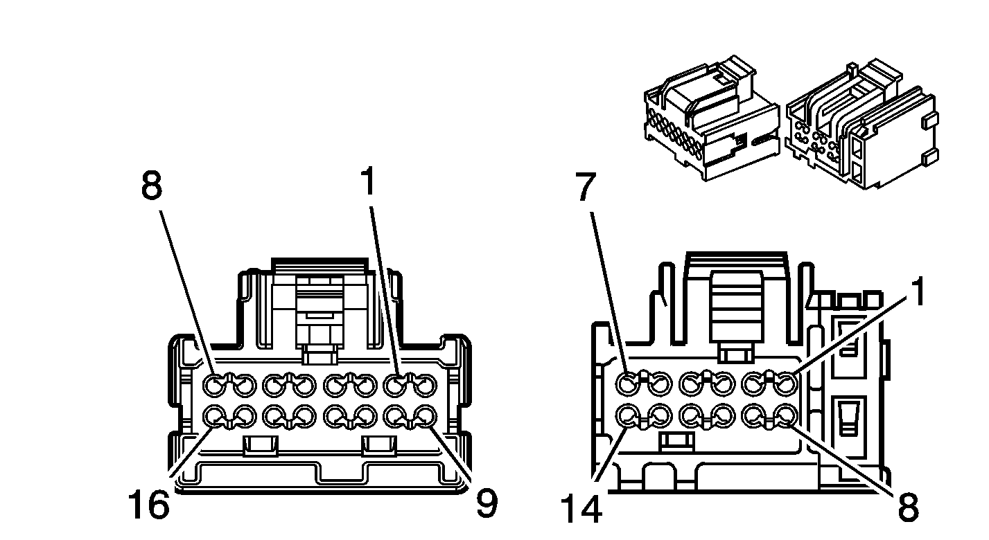
X212 Instrument Panel Harness to Instrument Panel Extension Harness (-Y91)
|
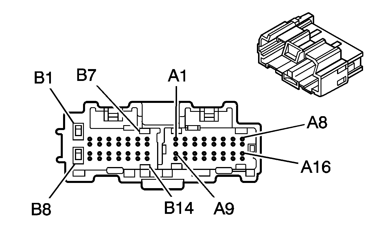
|
Connector Part Information
| Connector Part Information
|
Terminal Part Information
Connector Part Information
Terminal Part Information
| Terminal Part Information
|
Pin | Wire Color | Circuit No. | Function | Pin | Wire Color | Circuit No. | Function |
|---|---|---|---|---|---|---|---|
A1-A4 | -- | -- | Not Used | A1-A4 | -- | -- | Not Used |
A5 | 0.5 BN | 199 | Left Rear Speaker Output (+) | A5 | 0.5 BN | 199 | Left Rear Speaker Output (+) |
A6 | 0.5 D-BU | 46 | Right Rear Speaker Output (+) | A6 | 0.5 D-BU | 46 | Right Rear Speaker Output (+) |
A7-A12 | -- | -- | Not Used | A7-A12 | -- | -- | Not Used |
A13 | 0.5 YE | 116 | Left Rear Speaker Output (-) | A13 | 0.5 YE | 116 | Left Rear Speaker Output (-) |
A14 | 0.5 L-BU | 115 | Right Rear Speaker Output (-) | A14 | 0.5 L-BU | 115 | Right Rear Speaker Output (-) |
A15-A16 | -- | -- | Not Used | A15-A16 | -- | -- | Not Used |
B1 | 1 RD/WH | 340 | Battery Positive Voltage | B1 | 1 RD/WH | 340 | Battery Positive Voltage |
B2 | 0.5 TN | 201 | Left Front Speaker Output (+) | B2 | 0.5 TN | 201 | Left Front Speaker Output (+) |
B3 | 0.5 L-GN | 200 | Right Front Speaker Output (+) | B3 | 0.5 L-GN | 200 | Right Front Speaker Output (+) |
B4-B6 | -- | -- | Not Used | B4-B6 | -- | -- | Not Used |
B7 | 0.35 YE | 6817 | LED Backlight Dimming Control | B7 | 0.35 YE | 6817 | LED Backlight Dimming Control |
B8 | 1 BK | 2550 | Ground | B8 | 1 BK | 2550 | Ground |
B9 | 0.5 GY | 118 | Left Front Speaker Output (-) | B9 | 0.5 GY | 118 | Left Front Speaker Output (-) |
B10 | 0.5 D-GN | 117 | Right Front Speaker Output (-) | B10 | 0.5 D-GN | 117 | Right Front Speaker Output (-) |
B11-B12 | -- | -- | Not Used | B11-B12 | -- | -- | Not Used |
B13 | 0.35 D-GN | 5060 | Low Speed GMLAN Serial Data | B13 | 0.35 D-GN | 5060 | Low Speed GMLAN Serial Data |
B14 | -- | -- | Not Used | B14 | -- | -- | Not Used |
X214 Brake Clutch Harness to Fuse Block Jumper Harness (9L4)
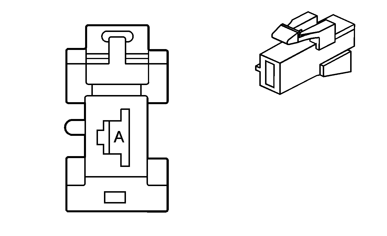
|
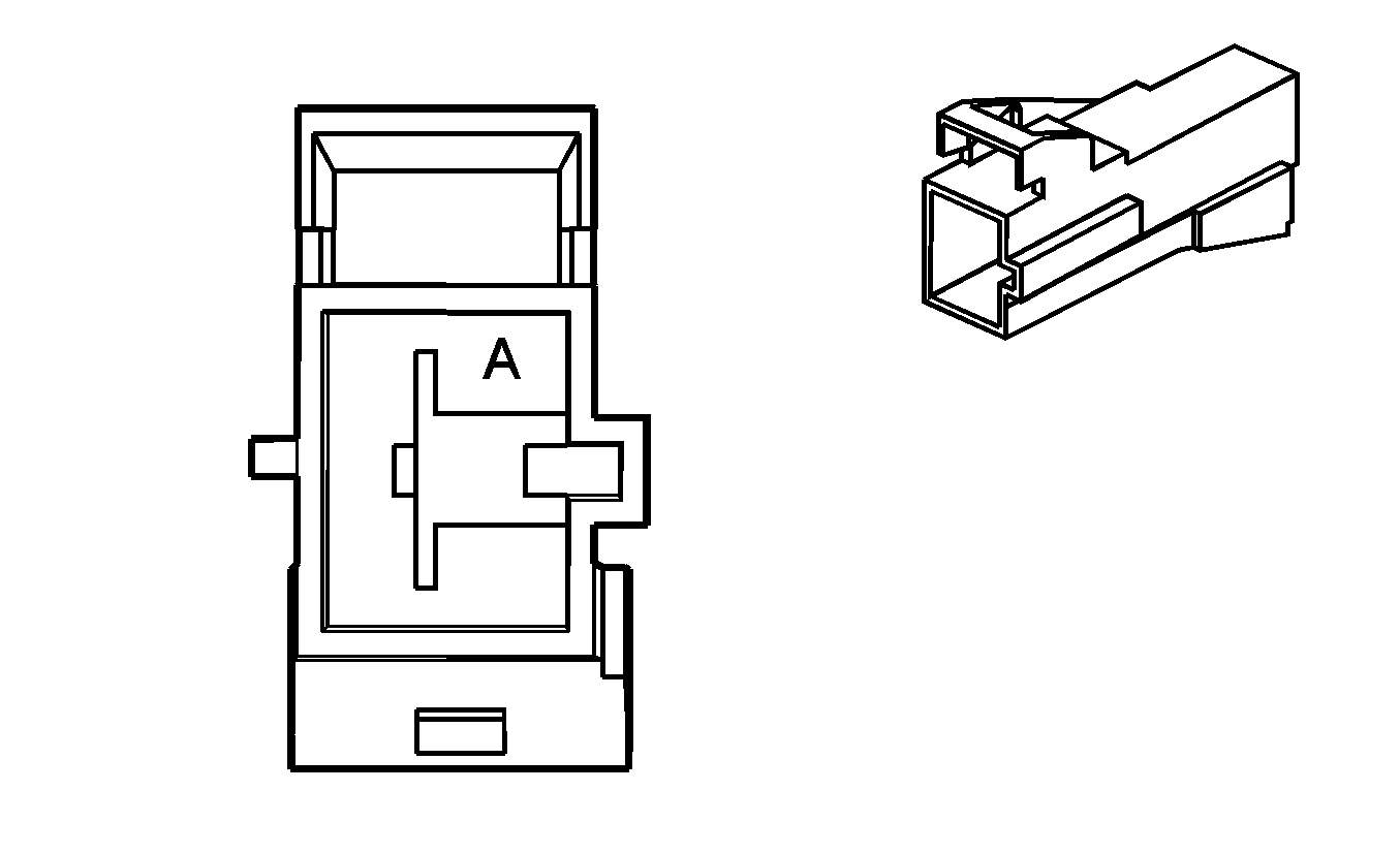
|
Connector Part Information
| Connector Part Information
|
Terminal Part Information
| Terminal Part Information
|
Pin | Wire Color | Circuit No. | Function | Pin | Wire Color | Circuit No. | Function |
|---|---|---|---|---|---|---|---|
A | 8 RD/BK | 102 | Battery Positive Voltage | A | 8 RD/BK | 102 | Battery Positive Voltage |
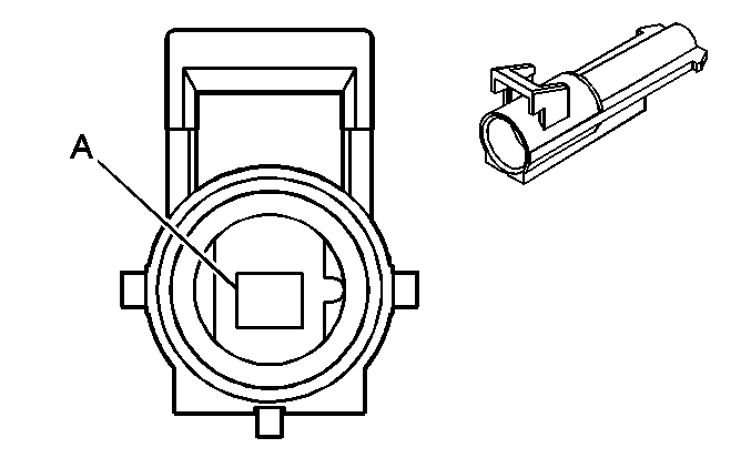
X219 Brake Clutch Harness to Fuse Block Jumper Harness (9L4)
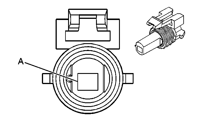
|
|
Connector Part Information
| Connector Part Information
|
Terminal Part Information
| Terminal Part Information
|
Pin | Wire Color | Circuit No. | Function | Pin | Wire Color | Circuit No. | Function |
|---|---|---|---|---|---|---|---|
A | 0.5 YE | 43 | Accessory Voltage | A | 0.5 YE | 43 | Accessory Voltage |
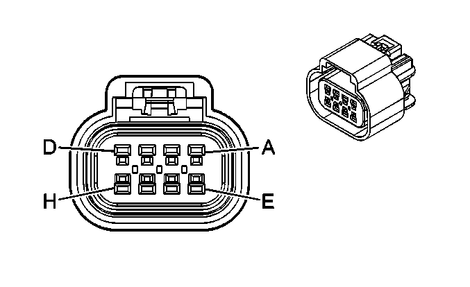
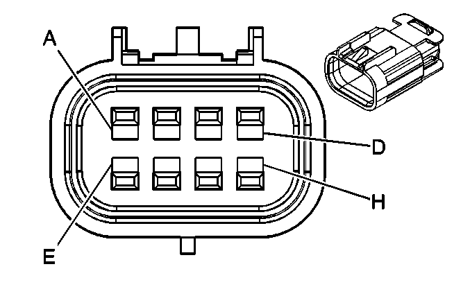
X220 Brake Clutch Harness to Chassis Harness (JL1)
|
|
Connector Part Information
| Connector Part Information
|
Terminal Part Information
| Terminal Part Information
|
Pin | Wire Color | Circuit No. | Function | Pin | Wire Color | Circuit No. | Function |
|---|---|---|---|---|---|---|---|
A | 0.35 TN | 7631 | Low Reference | A | 0.5 TN | 7631 | Low Reference |
B | 0.35 L-GN/BK | 7633 | Integrated Trailer Brake Controller User Gain Signal | B | 0.5 L-GN/BK | 7633 | Integrated Trailer Brake Controller User Gain Signal |
C | 0.35 YE | 7635 | Integrated Trailer Brake Controller Manual Apply Signal | C | 0.5 YE | 7635 | Integrated Trailer Brake Controller Manual Apply Signal |
D | 0.35 D-BU | 7632 | 5-Volt Reference | D | 0.5 D-BU | 7632 | 5-Volt Reference |
E | 0.35 BN | 7634 | Integrated Trailer Brake Controller Redundant Manual Apply Signal | E | 0.5 BN | 7634 | Integrated Trailer Brake Controller Redundant Manual Apply Signal |
F | -- | -- | Not Used | F | -- | -- | Not Used |
G | 0.35 L-BU/WH | 6311 | TCC Brake Signal | G | 0.5 L-BU/WH | 6311 | TCC Brake Signal |
H | 0.35 PK | 239 | Ignition 1 Voltage | H | 0.5 PK | 239 | Ignition 1 Voltage |
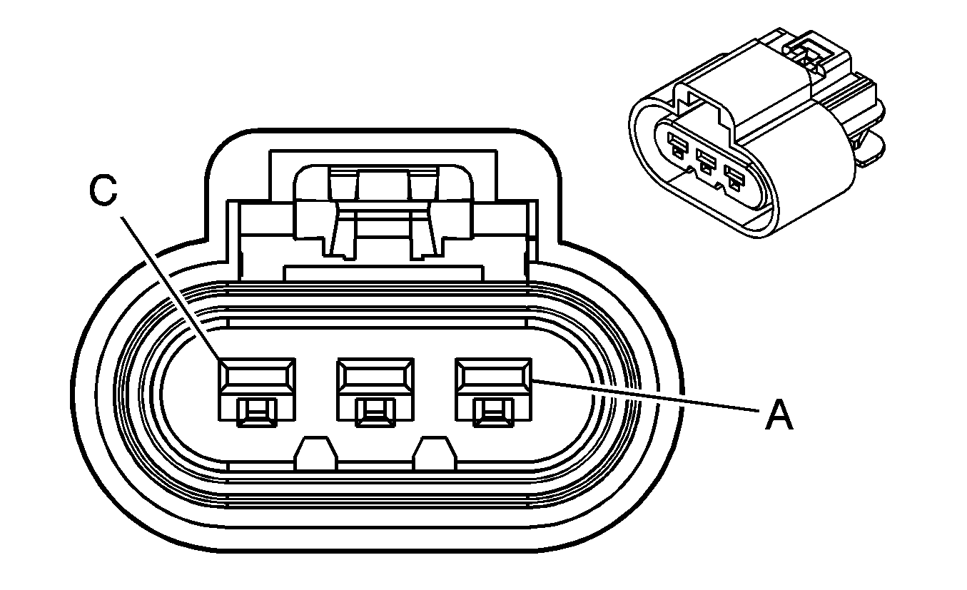
X224 Brake Clutch Harness to Beacon Harness (5Y0/5X7)
|
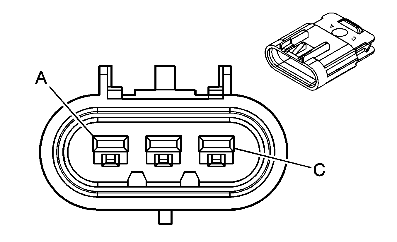
|
Connector Part Information
| Connector Part Information
|
Terminal Part Information
| Terminal Part Information
|
Pin | Wire Color | Circuit No. | Function | Pin | Wire Color | Circuit No. | Function |
|---|---|---|---|---|---|---|---|
A | 3 RD/WH | 2340 | Battery Positive Voltage (5Y0) | A | 3 RD/WH | 2340 | Battery Positive Voltage (5Y0) |
B | 0.5 WH | 5990 | Emergency Lamp Switch Signal | B | 0.5 WH | 5990 | Emergency Lamp Switch Signal |
C | 0.5 BK | 1050 | Ground | C | 0.5 BK | 1050 | Ground |
X225 Brake Clutch Harness to Battery Positive Harness (9L4)

|

|
Connector Part Information
| Connector Part Information
|
Terminal Part Information
| Terminal Part Information
|
Pin | Wire Color | Circuit No. | Function | Pin | Wire Color | Circuit No. | Function |
|---|---|---|---|---|---|---|---|
A | 8 BK | 450 | Ground | A | 8 BK | 450 | Ground |
X226 Fuse Block Jumper Harness to Brake Clutch Harness (9L4)

|

|
Connector Part Information
| Connector Part Information
|
Terminal Part Information
| Terminal Part Information
|
Pin | Wire Color | Circuit No. | Function | Pin | Wire Color | Circuit No. | Function |
|---|---|---|---|---|---|---|---|
1 | 8 BK | 450 | Ground | 1 | 8 BK | 450 | Ground |
X227 LED Indicator Harness to SPO Theft Harness (SPO Alarm)
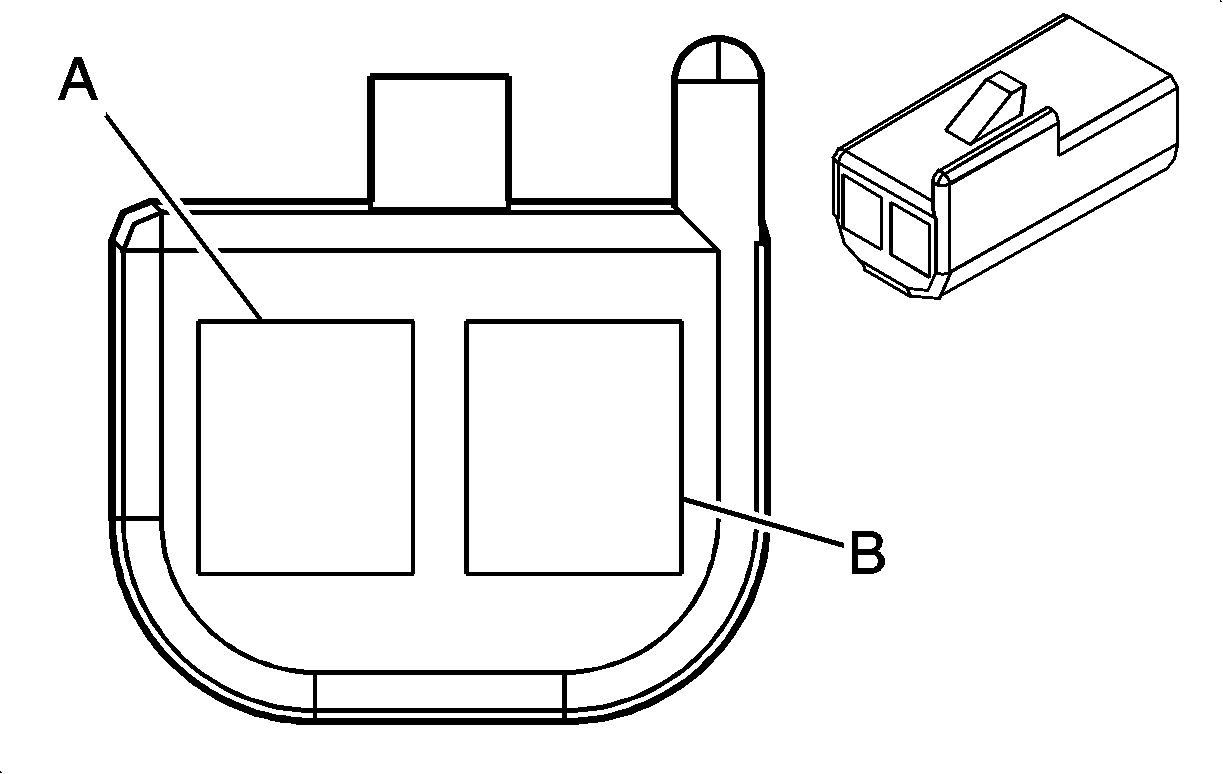
|
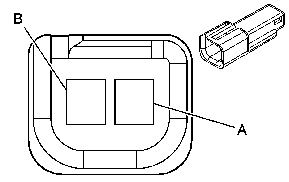
|
Connector Part Information
| Connector Part Information
|
Terminal Part Information
| Terminal Part Information
|
Pin | Wire Color | Circuit No. | Function | Pin | Wire Color | Circuit No. | Function |
|---|---|---|---|---|---|---|---|
A | 0.5 RD/WH | 4540 | Battery Positive Voltage | A | 0.5 RD/WH | 4540 | Battery Positive Voltage |
B | 0.5 GY | 728 | Security Indicator Control | B | 0.5 GY | 728 | Security Indicator Control |
X228 Beacon Harness to Chassis Harness (5Y0)

|
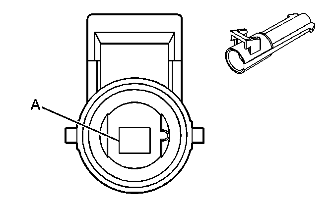
|
Connector Part Information
| Connector Part Information
|
Terminal Part Information
| Terminal Part Information
|
Pin | Wire Color | Circuit No. | Function | Pin | Wire Color | Circuit No. | Function |
|---|---|---|---|---|---|---|---|
A | 3 D-GN | 5989 | Emergency Lamp Relay Contact Control | A | 3 D-GN | 5989 | Emergency Lamp Relay Contact Control |
X275 Inflatable Restraint Steering Wheel Module Coil to Body Harness

|

|
Connector Part Information
| Connector Part Information
|
Terminal Part Information
| Terminal Part Information
|
Pin | Wire Color | Circuit No. | Function | Pin | Wire Color | Circuit No. | Function |
|---|---|---|---|---|---|---|---|
A1 | 0.5 TN | 3021 | Steering Wheel Module - Stage 1 - High Control | A1 | 0.5 TN | 3021 | Steering Wheel Module - Stage 1 - High Control |
A2 | 0.5 BN | 3020 | Steering Wheel Module - Stage 1 - Low Control | A2 | 0.5 BN | 3020 | Steering Wheel Module - Stage 1 - Low Control |
B1 | 0.5 WH | 3023 | Steering Wheel Module - Stage 2 - High Control (10 Series) | B1 | 0.5 WH | 3023 | Steering Wheel Module - Stage 2 - High Control (10 Series) |
B2 | 0.5 PK | 3022 | Steering Wheel Module - Stage 2 - Low Control (10 Series) | B2 | 0.5 PK | 3022 | Steering Wheel Module - Stage 2 - Low Control (10 Series) |
X276 Steering Column Harness to Inflatable Restraint Steering Wheel Module Coil (KA9)
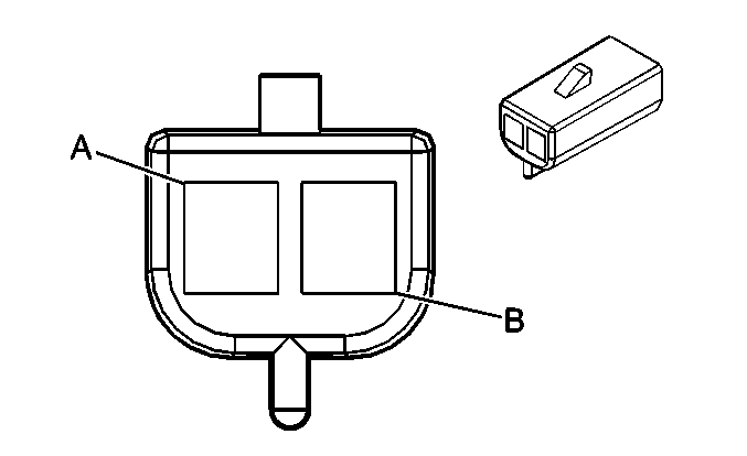
|
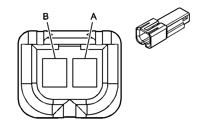
|
Connector Part Information
| Connector Part Information
|
Terminal Part Information
| Terminal Part Information
|
Pin | Wire Color | Circuit No. | Function | Pin | Wire Color | Circuit No. | Function |
|---|---|---|---|---|---|---|---|
A | 0.8 PK | 1639 | Ignition 1 Voltage | A | 0.8 BN | 1639 | Ignition 1 Voltage |
B | 0.8 BK | 1050 | Ground | B | 0.8 BK | 1050 | Ground |
X277 Inflatable Restraint Steering Wheel Module Coil to Heated Steering Wheel Harness (KA9)

|

|
Connector Part Information
| Connector Part Information
|
Terminal Part Information
| Terminal Part Information
|
Pin | Wire Color | Circuit No. | Function | Pin | Wire Color | Circuit No. | Function |
|---|---|---|---|---|---|---|---|
A | 0.8 BN | 1639 | Ignition 1 Voltage | A | 0.8 RD | 1639 | Ignition 1 Voltage |
B | 0.8 BK | 1050 | Ground | B | 0.8 BK | 1050 | Ground |
X300 Chassis Harness to Engine Harness (Gas)

|

|
Connector Part Information
| Connector Part Information
|
Terminal Part Information
| Terminal Part Information
|
Pin | Wire Color | Circuit No. | Function | Pin | Wire Color | Circuit No. | Function |
|---|---|---|---|---|---|---|---|
A | 0.5 PU | 1589 | Fuel Level Sensor Signal - Primary | A | 0.35 PU | 1589 | Fuel Level Sensor Signal - Primary |
B | 0.5 D-GN/WH | 465 | Fuel Pump Relay Control - Primary (-4.3L/LMG/LY6/LC9) | B | 0.35 D-GN/WH | 465 | Fuel Pump Relay Control - Primary (-4.3L/LMG/LY6/LC9) |
0.5 TN | 1465 | Fuel Pump Relay Control - Secondary (LY6) | 0.35 TN | 1465 | Fuel Pump Relay Control - Secondary (LY6) | ||
C | 0.5 GY | 2709 | 5-Volt Reference | C | 0.35 GY | 2709 | 5-Volt Reference |
D | 0.5 D-GN | 890 | Fuel Tank Pressure Sensor Signal | D | 0.35 D-GN | 890 | Fuel Tank Pressure Sensor Signal |
E | 0.5 YE/BK | 1827 | Vehicle Speed Signal | E | 0.35 YE/BK | 1827 | Vehicle Speed Signal |
F | 0.5 WH | 1310 | EVAP Canister Vent Solenoid Control | F | 0.35 WH | 1310 | EVAP Canister Vent Solenoid Control |
G | 0.5 L-BU | 1937 | Fuel Level Sensor Signal - Secondary (LY6) | G | 0.5 L-BU | 1937 | Fuel Level Sensor Signal - Secondary (LY6) |
H | 0.5 TN/BK | 6049 | Low Reference | H | 0.35 TN/BK | 6049 | Low Reference |
X300 Chassis Harness to Engine Chassis Harness (Diesel)
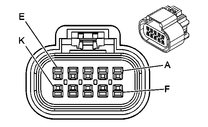
|
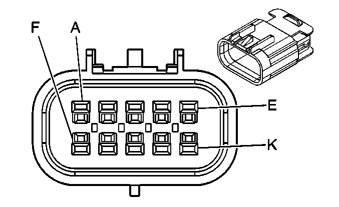
|
Connector Part Information
| Connector Part Information
|
Terminal Part Information
| Terminal Part Information
|
Pin | Wire Color | Circuit No. | Function | Pin | Wire Color | Circuit No. | Function |
|---|---|---|---|---|---|---|---|
A | 0.5 PU | 1589 | Fuel Level Sensor Signal -Primary | A | 0.5 PU | 1589 | Fuel Level Sensor Signal -Primary |
B | -- | -- | Not Used | B | -- | -- | Not Used |
C | 0.5 GY | 6054 | 5-Volt Reference | C | 0.5 GY | 6054 | 5-Volt Reference |
D | 0.5 YE/BK | 6055 | Low Reference | D | 0.5 YE/BK | 6055 | Low Reference |
E | 0.5 YE/BK | 1827 | Vehicle Speed Signal | E | 0.5 YE/BK | 1827 | Vehicle Speed Signal |
F | 0.5 D-BU | 6053 | DPF Sensor Signal | F | 0.5 D-BU | 6053 | DPF Sensor Signal |
G | 0.5 L-BU/WH | 1937 | Fuel Level Sensor Signal - Secondary | G | 0.5 L-BU | 1937 | Fuel Level Sensor Signal - Secondary (+31 Series -NQZ) |
H | 0.5 TN/BK | 6049 | Low Reference | H | 0.5 TN/BK | 6049 | Low Reference |
J | 0.5 GY/BK | 6783 | Low Reference | J | 0.5 BN/WH | 6783 | Low Reference |
K | 0.5 L-BU | 5377 | Exhaust Gas Temperature Sensor | K | 0.5 L-BU | 5377 | Exhaust Gas Temperature Sensor |
X303 Body Harness to Driver Seat Harness (AN3)

|

|
Connector Part Information
| Connector Part Information
|
Terminal Part Information
| Terminal Part Information
|
Pin | Wire Color | Circuit No. | Function | Pin | Wire Color | Circuit No. | Function |
|---|---|---|---|---|---|---|---|
A1 | 1 L-BU | 2433 | Heated Seat Back Element Control | A1 | 1 L-BU | 2433 | Heated Seat Back Element Control |
A2 | 1 PK | 2480 | Passenger Heated Seat Cushion Element Control | A2 | 1 PK | 2480 | Passenger Heated Seat Cushion Element Control |
A3 | 0.5 PK | 5289 | Adjustable Pedal Sensor Signal | A3 | 0.5 PK | 5289 | Adjustable Pedal Sensor Signal (JF4) |
A4 | 0.35 D-GN | 5060 | Low Speed GMLAN Serial Data | A4 | 0.35 D-GN | 5060 | Low Speed GMLAN Serial Data |
A5 | 0.35 TN/WH | 238 | Seat Belt Switch - Left | A5 | 0.35 TN/WH | 238 | Seat Belt Switch - Left |
A6 | 0.35 L-GN | 5055 | Seat Position Sensor - Left - Signal | A6 | 0.35 L-GN | 5055 | Seat Position Sensor - Left - Signal |
A7 | 3 RD/WH | 5040 | Battery Positive Voltage | A7 | 3 RD/WH | 5040 | Battery Positive Voltage |
A8 | 0.35 PK | 5057 | Low Reference | A8 | 0.35 PK | 5057 | Low Reference |
0.35 PK | 5057 | Low Reference | |||||
A9 | -- | -- | Not Used | A9 | -- | -- | Not Used |
A10 | 0.35 GY | 2434 | Passenger Heated Seat Cushion Temperature Sensor Signal | A10 | 0.35 GY | 2434 | Passenger Heated Seat Cushion Temperature Sensor Signal |
A11 | 0.35 PK | 2435 | Low Reference | A11 | 0.35 PK | 2435 | Low Reference |
A12 | 0.35 TN | 2436 | Passenger Heated Seat Back Temperature Sensor Signal | A12 | 0.35 TN | 2436 | Passenger Heated Seat Back Temperature Sensor Signal |
A13 | 0.35 TN | 2482 | Low Reference | A13 | 0.35 TN | 2482 | Low Reference |
A14 | 0.5 TN | 6207 | 5-Volt Reference | A14 | 0.35 TN | 6207 | 5-Volt Reference (JF4) |
A15 | 0.5 GY | 6206 | Low Reference | A15 | 0.35 GY | 6206 | Low Reference (JF4) |
B1 | 0.35 PU | 5286 | Adjustable Pedals Relay Forward Control | B1 | 0.35 PU | 5286 | Adjustable Pedals Relay Forward Control (JF4) |
B2 | 0.35 OG/BK | 5285 | Adjustable Pedals Relay Rearward Control | B2 | 0.35 YE | 5285 | Adjustable Pedals Relay Rearward Control (JF4) |
B3 | 1 PU | 5130 | Adjustable Pedals Relay Forward Control | B3 | 1 PU | 5130 | Adjustable Pedals Relay Forward Control (JF4) |
B4 | 1 YE | 5129 | Adjustable Pedals Relay Rearward Control | B4 | 1 OG/BK | 5129 | Adjustable Pedals Relay Rearward Control (JF4) |
B5 | 0.35 PU/WH | 6205 | Driver Position Switch High Reference | B5 | 0.35 PU/WH | 6205 | Driver Position Switch High Reference (JF4) |
B6 | 0.5 RD/WH | 1140 | Battery Positive Voltage | B6 | 0.5 RD/WH | 1140 | Battery Positive Voltage |
B7 | 1 D-BU | 2479 | Passenger Heated Seat Element Supply Voltage | B7 | 1 D-BU | 2479 | Passenger Heated Seat Element Supply Voltage |
B8 | 3 BK | 1150 | Ground | B8 | 3 BK | 1150 | Ground |
B9-B15 | -- | -- | Not Used | B9-B15 | -- | -- | Not Used |
X303 Body Harness to Driver Seat Harness (-AN3)
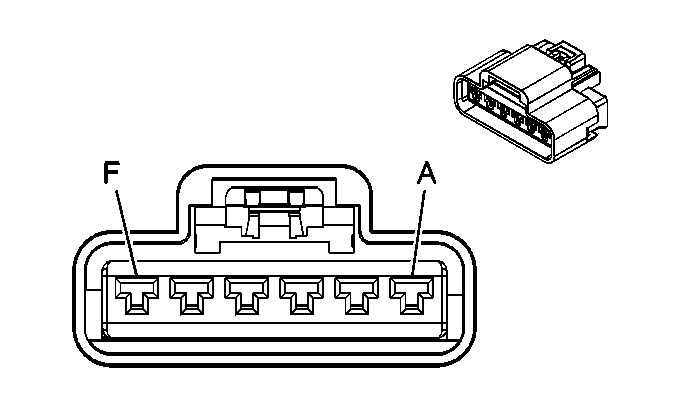
|
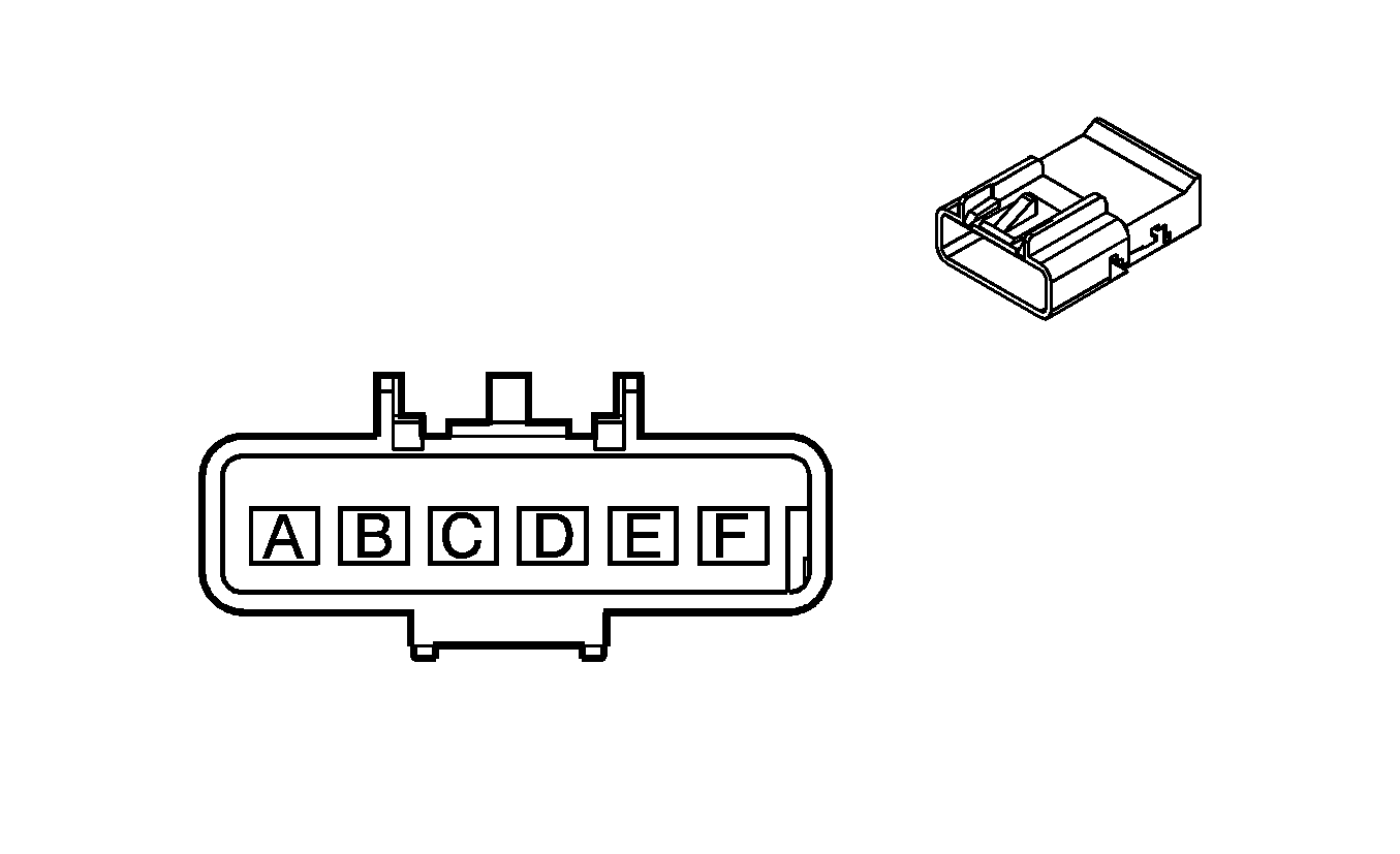
|
Connector Part Information
| Connector Part Information
|
Terminal Part Information
| Terminal Part Information
|
Pin | Wire Color | Circuit No. | Function | Pin | Wire Color | Circuit No. | Function |
|---|---|---|---|---|---|---|---|
A | 3 RD/WH | 5040 | Battery Positive Voltage | A | 3 RD/WH | 5040 | Battery Positive Voltage (AG1) |
B | 0.35 TN/WH | 238 | Seat Belt Switch - Left | B | 0.35 TN/WH | 238 | Seat Belt Switch - Left |
C | 0.35 L-GN | 5055 | Seat Position Sensor - Left - Signal (10 Series) | C | 0.35 L-GN | 5055 | Seat Position Sensor - Left - Signal (10 Series) |
D | 0.35 PK | 5057 | Low Reference | D | 0.35 PK | 5057 | Low Reference |
0.35 PK | 5057 | Low Reference | |||||
E | -- | -- | Not Used | E | -- | -- | Not Used |
F | 3 BK | 1150 | Ground (AG1) | F | 3 PK | 1150 | Ground (AG1) |
X304 Headliner Harness to Overhead Console Harness
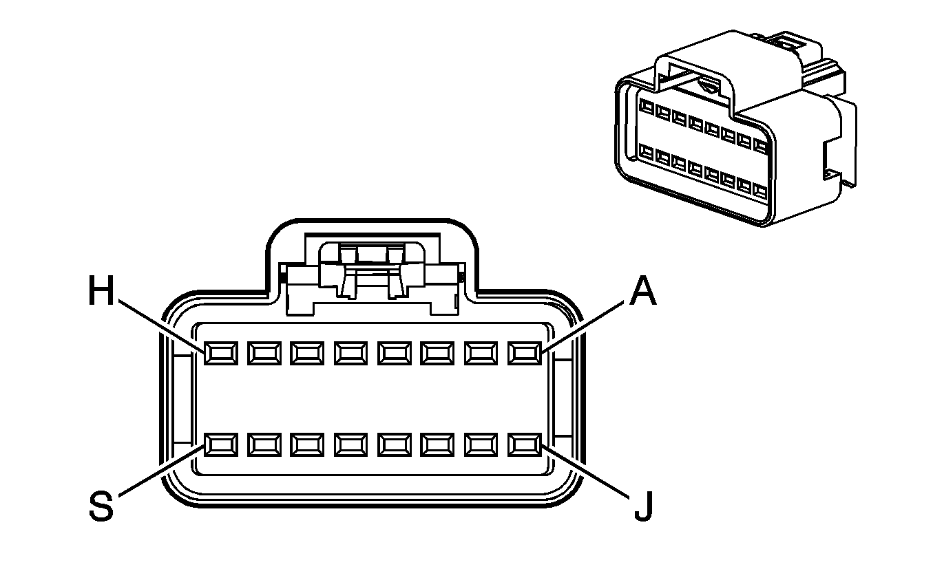
|
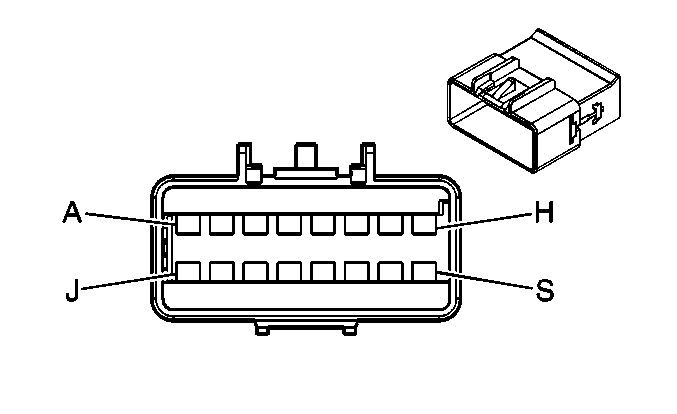
|
Connector Part Information
| Connector Part Information
|
Terminal Part Information
| Terminal Part Information
|
Pin | Wire Color | Circuit No. | Function | Pin | Wire Color | Circuit No. | Function |
|---|---|---|---|---|---|---|---|
A | 0.5 BK | 1050 | Ground | A | 0.5 BK | 1050 | Ground |
B | 0.5 RD/WH | 240 | Battery Positive Voltage | B | 0.5 RD/WH | 240 | Battery Positive Voltage (UG1) |
0.5 RD/WH | 240 | Battery Positive Voltage (5X7/5Y0/TRW) | |||||
C | 0.35 BN/WH | 230 | Instrument Panel Lamps Dimming Control (TRW/UG1/A48) | C | 0.35 BN/WH | 230 | Instrument Panel Lamps Dimming Control (TRW/UG1/A48) |
D | 0.35 PK | 1139 | Ignition 1 Voltage | D | 0.35 PK | 1139 | Ignition 1 Voltage |
E | -- | -- | Not Used | E | -- | -- | Not Used |
F | 0.35 GY | 655 | Cellular Telephone Voice Signal | F | 0.35 GY | 655 | Cellular Telephone Voice Signal (UE1/U3U/UVB) |
G | 0.35 BARE | 514 | Low Reference (UE1/U3U/UVB) | G | 0.35 D-GN | 654 | Low Reference (UE1/U3U/UVB) |
H | 0.35 OG | 6815 | Inadvertent Power Control | H | 0.35 OG | 6815 | Inadvertent Power Control |
J | 0.5 GY | 157 | Courtesy Lamp Control | J | 0.5 GY | 157 | Courtesy Lamp Control |
K | 0.35 WH | 6192 | Power Sliding Window Switch Close Signal (A48) | K | 0.35 WH | 6192 | Power Sliding Window Switch Close Signal (A48) |
L | 0.35 YE | 43 | Accessory Voltage (A48) | L | 0.35 YE | 43 | Accessory Voltage (A48) |
M | 0.35 TN | 6191 | Power Sliding Window Switch Open Signal (A48) | M | 0.35 TN | 6191 | Power Sliding Window Switch Open Signal (A48) |
N | 0.35 D-BU | 2307 | Passenger Air Bag On Indicator Control (AL0/C99) | N | 0.35 D-BU | 2307 | Passenger Air Bag On Indicator Control (AL0/C99) |
P | 0.35 D-GN/BK | 2308 | Passenger Air Bag Off Indicator Control (AL0/C99) | P | 0.35 D-GN/BK | 2308 | Passenger Air Bag Off Indicator Control (AL0/C99) |
R | 0.35 PU | 5234 | Passenger Seat Belt Indicator | R | 0.35 PU | 5234 | Passenger Seat Belt Indicator |
S | -- | -- | Not Used | S | -- | -- | Not Used |
X305 Body Harness to Passenger Seat Harness (AN3)

|

|
Connector Part Information
| Connector Part Information
|
Terminal Part Information
| Terminal Part Information
|
Pin | Wire Color | Circuit No. | Function | Pin | Wire Color | Circuit No. | Function |
|---|---|---|---|---|---|---|---|
A1 | -- | -- | Not Used | A1 | -- | -- | Not Used |
A2 | 1 PK | 2480 | Passenger Heated Seat Cushion Element Control | A2 | 1 PK | 2480 | Passenger Heated Seat Cushion Element Control |
A3 | 1 L-BU | 2433 | Heated Seat Back Element Control | A3 | 1 L-BU | 2433 | Heated Seat Back Element Control |
A4 | -- | -- | Not Used | A4 | -- | -- | Not Used |
A5 | 0.35 OG | 1362 | Seat Belt Switch - Right - Signal | A5 | 0.35 OG | 1362 | Seat Belt Switch - Right - Signal |
A6 | -- | -- | Not Used | A6 | -- | -- | Not Used |
A7 | 0.35 GY | 2434 | Passenger Heated Seat Cushion Temperature Sensor Signal | A7 | 0.35 GY | 2434 | Passenger Heated Seat Cushion Temperature Sensor Signal |
A8 | 1 D-BU | 2479 | Passenger Heated Seat Element Supply Voltage | A8 | 1 D-BU | 2479 | Passenger Heated Seat Element Supply Voltage |
A9 | 3 BK | 1250 | Ground | A9 | 3 BK | 1250 | Ground |
A10 | 0.35 D-GN | 5060 | Low Speed GMLAN Serial Data | A10 | 0.35 D-GN | 5060 | Low Speed GMLAN Serial Data |
A11-A15 | -- | -- | Not Used | A11-A15 | -- | -- | Not Used |
B1 | -- | -- | Not Used | B1 | -- | -- | Not Used |
B2 | 0.5 RD/WH | 4440 | Battery Positive Voltage | B2 | 0.5 RD/WH | 4440 | Battery Positive Voltage |
B3 | 0.5 BK/WH | 2751 | Ground | B3 | 0.5 BK/WH | 2751 | Ground |
B4 | 0.35 PK | 2435 | Low Reference | B4 | 0.35 PK | 2435 | Low Reference |
B5 | 0.35 PK | 5057 | Low Reference | B5 | 0.35 PK | 5057 | Low Reference |
B6 | 0.35 TN | 2482 | Low Reference | B6 | 0.35 TN/BK | 2482 | Low Reference |
B7 | 0.35 TN | 2436 | Passenger Heated Seat Back Temperature Sensor Signal | B7 | 0.35 TN | 2436 | Passenger Heated Seat Back Temperature Sensor Signal |
B8 | -- | -- | Not Used | B8 | -- | -- | Not Used |
B9 | 3 RD/WH | 1440 | Battery Positive Voltage | B9 | 3 RD/WH | 1440 | Battery Positive Voltage |
B10-B15 | -- | -- | Not Used | B10-B15 | -- | -- | Not Used |
X305 Body Harness to Passenger Seat Harness (-AN3)
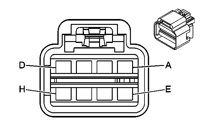
|
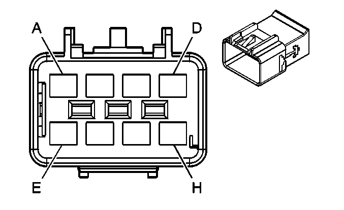
|
Connector Part Information
| Connector Part Information
|
Terminal Part Information
| Terminal Part Information
|
Pin | Wire Color | Circuit No. | Function | Pin | Wire Color | Circuit No. | Function |
|---|---|---|---|---|---|---|---|
A | 3 RD/WH | 1440 | Battery Positive Voltage (AG2) | A | 3 RD/WH | 1440 | Battery Positive Voltage (AG2) |
B | 3 BK | 1250 | Ground (AG2) | B | 3 BK | 1250 | Ground (AG2) |
C | -- | -- | Not Used | C | -- | -- | Not Used |
D | 0.35 PK | 5057 | Low Reference (10 Series) | D | 0.35 PK | 5057 | Low Reference (10 Series) |
E | 0.35 OG | 1362 | Seat Belt Switch - Right - Signal (10 Series) | E | 0.35 OG | 1362 | Seat Belt Switch - Right - Signal (10 Series) |
F | 0.35 D-GN | 5060 | Low Speed GMLAN Serial Data (AL0) | F | 0.35 D-GN | 5060 | Low Speed GMLAN Serial Data (AL0) |
G | 0.5 RD/WH | 4440 | Battery Positive Voltage (AL0) | G | 0.5 RD/WH | 4440 | Battery Positive Voltage (AL0) |
H | 0.5 BK/WH | 2751 | Ground (AL0) | H | 0.5 BK/WH | 2751 | Ground (AL0) |
X306 Headliner Harness to Right A-Pillar Harness (U42)

|

|
Connector Part Information
| Connector Part Information
|
Terminal Part Information
| Terminal Part Information
|
Pin | Wire Color | Circuit No. | Function | Pin | Wire Color | Circuit No. | Function |
|---|---|---|---|---|---|---|---|
A | 0.35 PK/BK | 5844 | Video Bright Control | A | 0.35 PK/BK | 5844 | Video Bright Control |
B | 0.35 WH/BK | 5335 | DVD Video Signal (-) | B | 0.35 WH/BK | 5335 | DVD Video Signal (-) |
C | 0.35 BARE | 6976 | Drain Wire | C | 0.35 BARE | 6976 | Drain Wire |
D | 0.35 D-GN | 6975 | DVD Video Signal (+) | D | 0.35 D-GN | 6975 | DVD Video Signal (+) |
E | 0.35 L-GN/BK | 5845 | Video Module Signal | E | 0.35 L-GN/BK | 5845 | Video Module Signal |
F | 0.5 RD/WH | 3240 | Battery Positive Voltage | F | 0.5 RD/WH | 3240 | Battery Positive Voltage |
G | 0.5 BK | 2550 | Ground | G | 0.5 BK | 2550 | Ground |
H | 0.35 WH | 7066 | Entertainment Remote Enable Signal | H | 0.35 WH | 7066 | Entertainment Remote Enable Signal |
X309 Body Harness to Console Harness (Y91)

|

|
Connector Part Information
| Connector Part Information
|
Terminal Part Information
| Terminal Part Information
|
Pin | Wire Color | Circuit No. | Function | Pin | Wire Color | Circuit No. | Function |
|---|---|---|---|---|---|---|---|
A-D | -- | -- | Not Used | A-D | -- | -- | Not Used |
E | 0.8 BN | 199 | Left Rear Speaker Output (+) | E | 0.8 BN | 199 | Left Rear Speaker Output (+) |
F | 0.8 YE | 116 | Left Rear Speaker Output (-) | F | 0.8 YE | 116 | Left Rear Speaker Output (-) |
G | 0.8 D-BU | 46 | Right Rear Speaker Output (+) | G | 0.8 D-BU | 46 | Right Rear Speaker Output (+) |
H | 0.8 L-BU | 115 | Right Rear Speaker Output (-) | H | 0.8 L-BU | 115 | Right Rear Speaker Output (-) |
X313 Sunroof Harness (CF5) or Overhead Console Harness (TRW/5X7/5Y0) to Right A-Pillar Harness (CF5/TRW/5X7/5Y0)
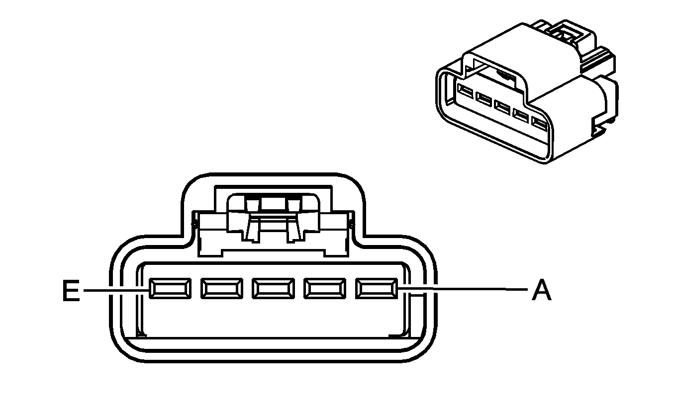
|
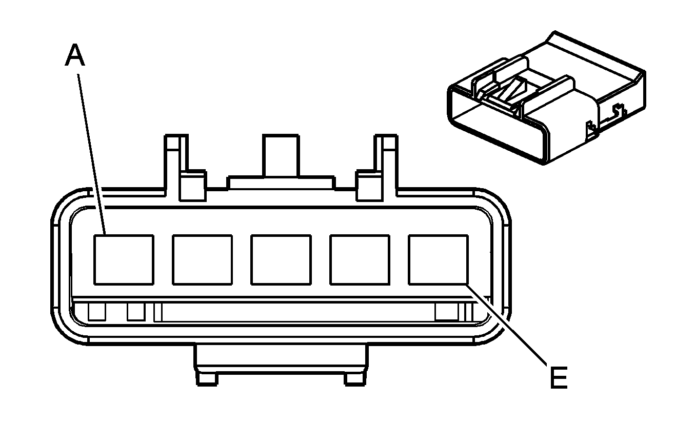
|
Connector Part Information
| Connector Part Information
|
Terminal Part Information
| Terminal Part Information
|
Pin | Wire Color | Circuit No. | Function | Pin | Wire Color | Circuit No. | Function |
|---|---|---|---|---|---|---|---|
A | 2 RD/WH | 3140 | Battery Positive Voltage (CF5/TRW) | A | 2 RD/WH | 3140 | Battery Positive Voltage (CF5/TRW) |
B | 0.5 WH | 5990 | Emergency Lamp Switch Signal (5Y0/5X7) | B | 0.5 WH | 5990 | Emergency Lamp Switch Signal (5Y0/5X7) |
0.35 YE | 43 | Accessory Voltage (CF5) | 0.35 YE | 43 | Accessory Voltage (CF5) | ||
C | 0.35 BN/WH | 230 | Instrument Panel Lamps Dimming Control (CF5) | C | 0.5 BN/WH | 230 | Instrument Panel Lamps Dimming Control (CF5) |
D | -- | -- | Not Used | D | -- | -- | Not Used |
E | 2 BK | 1050 | Ground | E | 2 BK | 1050 | Ground |
X318 Headliner Harness to CHMSL Harness
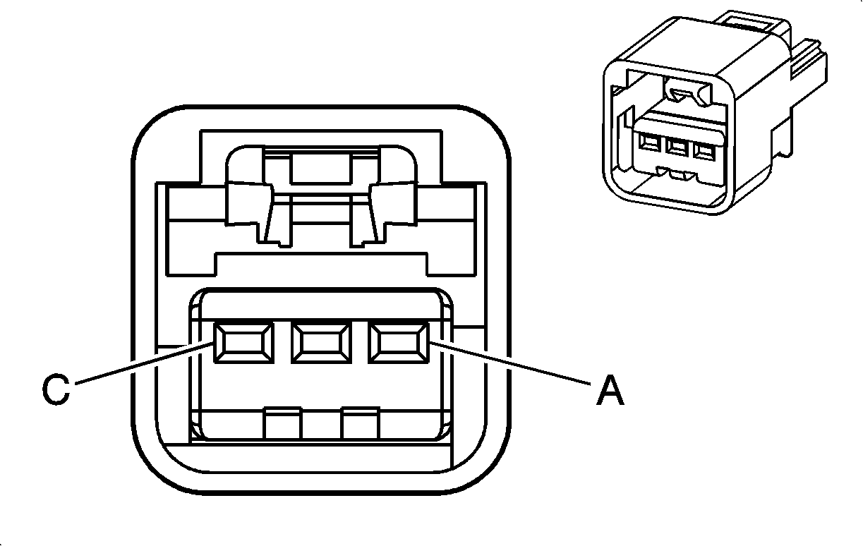
|
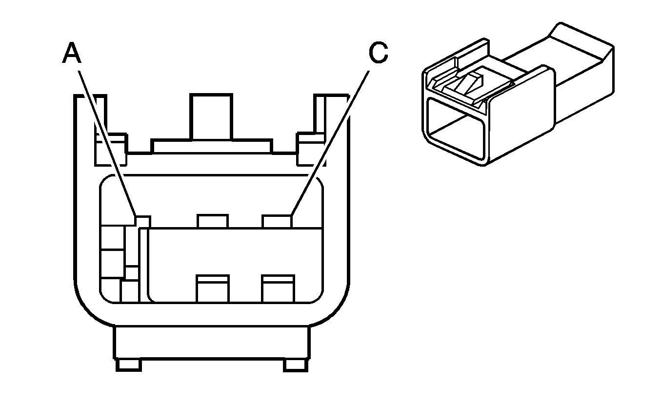
|
Connector Part Information
| Connector Part Information
|
Terminal Part Information
| Terminal Part Information
|
Pin | Wire Color | Circuit No. | Function | Pin | Wire Color | Circuit No. | Function |
|---|---|---|---|---|---|---|---|
A | 0.5 WH/BK | 158 | Courtesy Lamp Supply Voltage | A | 0.5 WH/BK | 158 | Courtesy Lamp Supply Voltage |
B | 0.5 OG | 1054 | Stop Lamp Supply Voltage Signal | B | 0.5 L-BU | 1054 | Stop Lamp Supply Voltage Signal |
C | 0.5 BK | 1050 | Ground | C | 0.5 BK | 1050 | Ground |
X319 Body Harness to Console Harness (AZ3/D07 +UQ3)
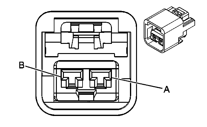
|
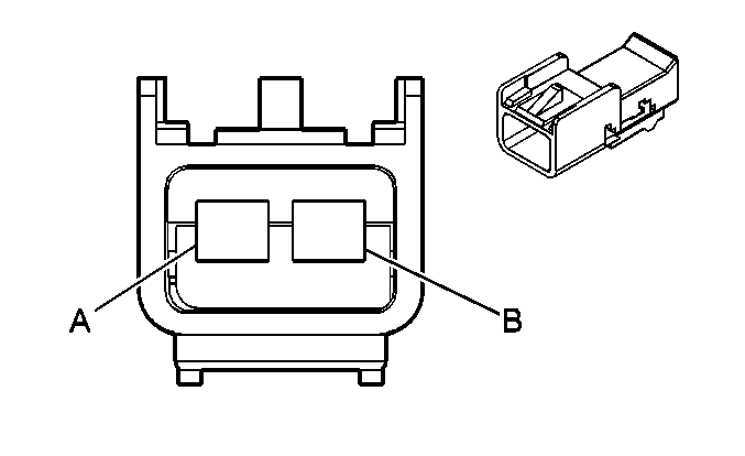
|
Connector Part Information
| Connector Part Information
|
Terminal Part Information
| Terminal Part Information
|
Pin | Wire Color | Circuit No. | Function | Pin | Wire Color | Circuit No. | Function |
|---|---|---|---|---|---|---|---|
A | 0.8 RD/WH | 6040 | Battery Positive Voltage | A | 0.8 RD/WH | 6040 | Battery Positive Voltage (AZ3) |
0.8 RD/WH | 1040 | Battery Positive Voltage (D07 +UQ3) | |||||
0.8 RD/WH | 1040 | Battery Positive Voltage (D07 +UQ3) | |||||
B | 0.8 BK | 1250 | Ground | B | 0.8 BK | 1250 | Ground (AZ3) |
0.8 BK | 1050 | Ground (D07 +UQ3) | |||||
0.8 BK | 1050 | Ground (D07 +UQ3) |
X320 Body Harness to Sliding Rear Window Jumper Harness (A48)
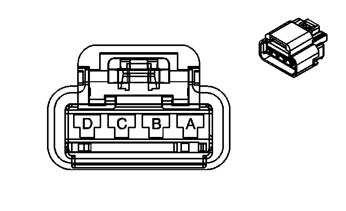
|
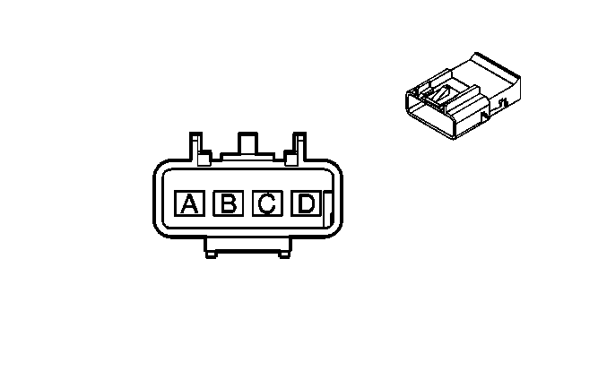
|
Connector Part Information
| Connector Part Information
|
Terminal Part Information
| Terminal Part Information
|
Pin | Wire Color | Circuit No. | Function | Pin | Wire Color | Circuit No. | Function |
|---|---|---|---|---|---|---|---|
A | 3 RD/WH | 3440 | Battery Positive Voltage | A | 2 RD/WH | 3140 | Battery Positive Voltage |
B | 2 BK | 2650 | Ground | B | 2 BK | 2650 | Ground |
C | 0.35 WH | 6192 | Power Sliding Window Switch Close Signal | C | 0.35 WH | 6192 | Power Sliding Window Switch Close Signal |
D | 0.35 TN | 6191 | Power Sliding Window Switch Open Signal | D | 0.35 TN | 6191 | Power Sliding Window Switch Open Signal |
X321 Body Harness to Headliner Harness (A48)

|

|
Connector Part Information
| Connector Part Information
|
Terminal Part Information
| Terminal Part Information
|
Pin | Wire Color | Circuit No. | Function | Pin | Wire Color | Circuit No. | Function |
|---|---|---|---|---|---|---|---|
A | -- | -- | Not Used | A | -- | -- | Not Used |
B | 0.35 TN | 6191 | Power Sliding Window Switch Open Signal | B | 0.35 TN | 6191 | Power Sliding Window Switch Open Signal |
C | 0.35 WH | 6192 | Power Sliding Window Switch Close Signal | C | 0.35 WH | 6192 | Power Sliding Window Switch Close Signal |
X322 Body Harness to UPA Jumper Harness (UD7)
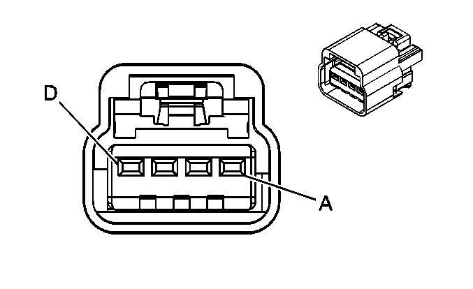
|
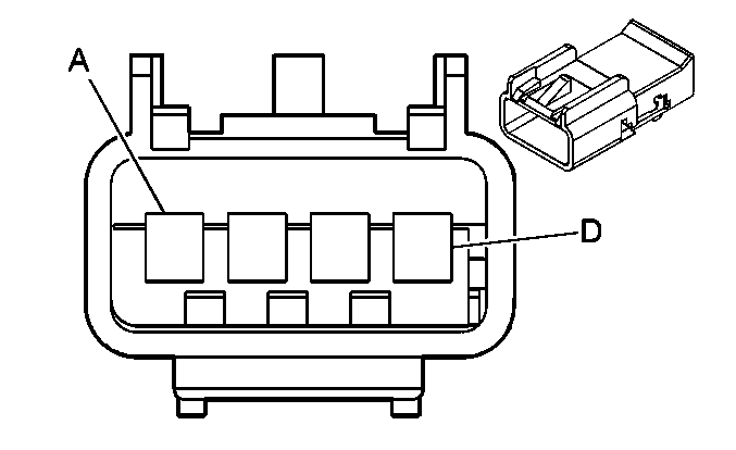
|
Connector Part Information
| Connector Part Information
|
Terminal Part Information
| Terminal Part Information
|
Pin | Wire Color | Circuit No. | Function | Pin | Wire Color | Circuit No. | Function |
|---|---|---|---|---|---|---|---|
A | 0.35 WH | 2370 | Telltale Assembly Supply Voltage | A | 0.35 WH | 2370 | Telltale Assembly Supply Voltage |
B | 0.35 OG | 2371 | Left Amber Indicator Control | B | 0.35 OG | 2371 | Left Amber Indicator Control |
C | 0.35 D-BU | 2372 | Center Amber Indicator Control | C | 0.35 D-BU | 2372 | Center Amber Indicator Control |
D | 0.35 GY | 2373 | Red Indicator Control | D | 0.35 GY | 2373 | Red Indicator Control |
X324 Driver Seat Harness to Driver Seat Jumper Harness (AN3)
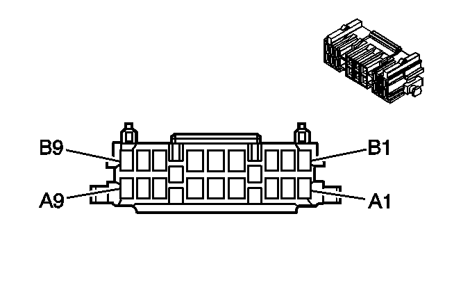
|
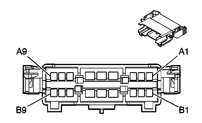
|
Connector Part Information
| Connector Part Information
|
Terminal Part Information
| Terminal Part Information
|
Pin | Wire Color | Circuit No. | Function | Pin | Wire Color | Circuit No. | Function |
|---|---|---|---|---|---|---|---|
A1-A2 | -- | -- | Not Used | A1-A2 | -- | -- | Not Used |
A3 | 0.35 TN/BK | 1062 | Driver Seat Lumbar Vertical Position Sensor Signal | A3 | 0.35 TN/BK | 1062 | Driver Seat Lumbar Vertical Position Sensor Signal |
A4 | 1 PK | 610 | Driver Seat Lumbar Motor Rearward Control | A4 | 2 PK | 610 | Driver Seat Lumbar Motor Rearward Control |
A5 | 1 TN | 768 | Driver Seat Lumbar Motor Up Control | A5 | 2 TN | 768 | Driver Seat Lumbar Motor Up Control |
A6 | 1 L-BU | 277 | Driver Seat Recline Motor Rearward Control | A6 | 2 L-BU | 277 | Driver Seat Recline Motor Rearward Control |
A7 | 0.35 WH/BK | 570 | Driver Seat Recline Motor Position Sensor Signal | A7 | 0.35 WH/BK | 570 | Driver Seat Recline Motor Position Sensor Signal |
A8-A9 | -- | -- | Not Used | A8-A9 | -- | -- | Not Used |
B1-B2 | -- | -- | Not Used | B1-B2 | -- | -- | Not Used |
B3 | 0.35 YE | 1063 | Driver Seat Lumbar Horizontal Position Sensor | B3 | 0.35 YE | 1063 | Driver Seat Lumbar Horizontal Position Sensor |
B4 | 1 D-BU | 611 | Driver Seat Lumbar Motor Forward Control | B4 | 2 D-BU | 611 | Driver Seat Lumbar Motor Forward Control |
B5 | 1 PU | 767 | Driver Seat Lumbar Motor Down Control | B5 | 2 PU | 767 | Driver Seat Lumbar Motor Down Control |
B6 | 1 L-GN | 276 | Driver Seat Recline Motor Forward Control | B6 | 2 L-GN | 276 | Driver Seat Recline Motor Forward Control |
B7 | 0.35 GY | 6206 | 5-Volt Reference | B7 | 0.35 GY | 6206 | 5-Volt Reference |
B8 | 0.35 TN | 6207 | Low Reference | B8 | 0.35 TN | 6207 | Low Reference |
B9 | -- | -- | Not Used | B9 | -- | -- | Not Used |
X325 Passenger Seat Harness to Passenger Seat Jumper Harness (AN3)

|

|
Connector Part Information
| Connector Part Information
|
Terminal Part Information
| Terminal Part Information
|
Pin | Wire Color | Circuit No. | Function | Pin | Wire Color | Circuit No. | Function |
|---|---|---|---|---|---|---|---|
A | 3 OG | 792 | Passenger Seat Lumbar Motor Down Control | A | 2 OG | 792 | Passenger Seat Lumbar Motor Down Control |
B | 3 PK | 793 | Passenger Seat Lumbar Motor Up Control | B | 2 PK | 793 | Passenger Seat Lumbar Motor Up Control |
C | 3 D-BU | 211 | Passenger Seat Lumbar Motor Forward Control | C | 2 D-BU | 211 | Passenger Seat Lumbar Motor Forward Control |
D | 3 WH | 210 | Passenger Seat Lumbar Motor Rearward Control | D | 2 WH | 210 | Passenger Seat Lumbar Motor Rearward Control |
E | 3 D-GN | 76 | Passenger Seat Recline Motor Forward | E | 2 D-GN | 76 | Passenger Seat Recline Motor Forward |
F | 3 D-BU | 77 | Passenger Seat Recline Motor Rearward | F | 2 D-BU | 77 | Passenger Seat Recline Motor Rearward |
X408 Chassis Harness to Rear Bumper Harness (UD7)

|

|
Connector Part Information
| Connector Part Information
|
Terminal Part Information
| Terminal Part Information
|
Pin | Wire Color | Circuit No. | Function | Pin | Wire Color | Circuit No. | Function |
|---|---|---|---|---|---|---|---|
A | 0.35 D-BU | 2374 | Object Sensor Supply Voltage | A | 0.5 L-BU | 2374 | Object Sensor Supply Voltage |
B | 0.5 YE | 2375 | LR Corner Object Sensor Signal | B | 0.5 YE | 2375 | LR Corner Object Sensor Signal |
C | 0.5 GY | 2379 | Low Reference | C | 0.5 GY | 2379 | Low Reference |
D | 0.5 OG | 2376 | LR Middle Object Sensor Signal | D | 0.5 OG | 2376 | LR Middle Object Sensor Signal |
E | 0.5 D-GN | 2377 | RR Middle Object Sensor Signal | E | 0.5 D-GN | 2377 | RR Middle Object Sensor Signal |
F | 0.5 PU | 2378 | RR Corner Object Sensor Signal | F | 0.5 PU | 2378 | RR Corner Object Sensor Signal |
G-H | -- | -- | Not Used | G-H | -- | -- | Not Used |
X414 Chassis Harness to Camper Harness (UY2/8S3)
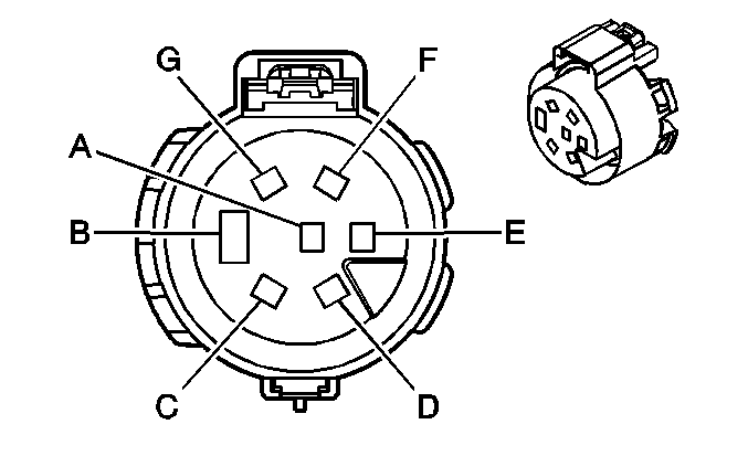
|
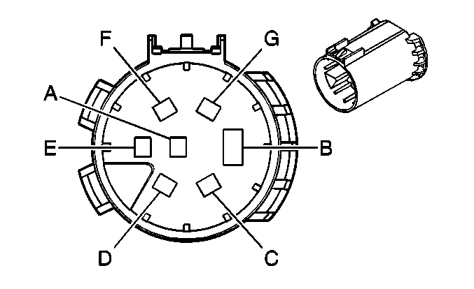
|
Connector Part Information
| Connector Part Information
|
Terminal Part Information
| Terminal Part Information
|
Pin | Wire Color | Circuit No. | Function | Pin | Wire Color | Circuit No. | Function |
|---|---|---|---|---|---|---|---|
A | 1.0 L-GN | 1624 | Trailer Backup Lamps Supply Voltage | A | 1.0 L-GN | 1624 | Trailer Backup Lamps Supply Voltage |
B | 5.0 WH | 22 | Ground | B | 5.0 WH | 22 | Ground |
C | 3.0 D-BU | 47 | Trailer Auxiliary Supply Voltage | C | 3.0 D-BU | 47 | Trailer Auxiliary Supply Voltage |
D | 0.8 D-GN | 1619 | Trailer Right Rear Turn/Stop Lamp Supply Voltage | D | 0.8 D-GN | 1619 | Trailer Right Rear Turn/Stop Lamp Supply Voltage |
E | 3.0 RD/BK | 742 | Battery Positive Voltage | E | 3.0 RD/BK | 742 | Battery Positive Voltage |
F | 1.0 BN | 2109 | Trailer Park Lamps Supply Voltage | F | 1.0 BN | 2109 | Trailer Park Lamps Supply Voltage |
G | 0.8 YE | 1618 | Trailer Left Rear Turn/Stop Lamp Supply Voltage | G | 0.8 YE | 1618 | Trailer Left Rear Turn/Stop Lamp Supply Voltage |
X415 Rear Bumper Harness to Left Hip Lamp Harness (RO5)
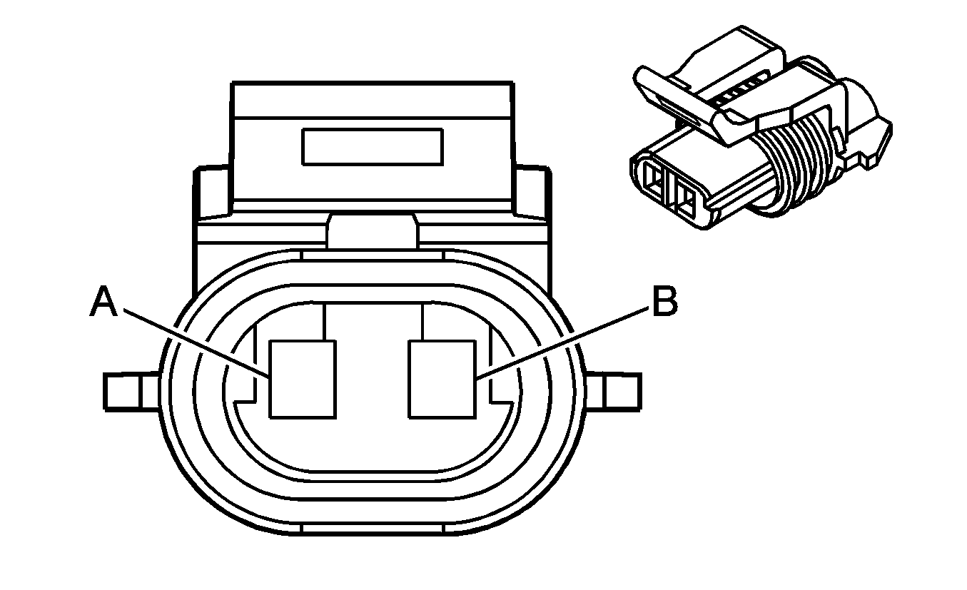
|
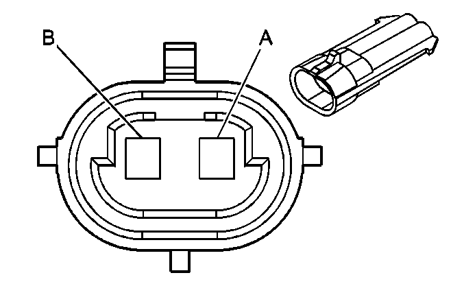
|
Connector Part Information
| Connector Part Information
|
Terminal Part Information
| Terminal Part Information
|
Pin | Wire Color | Circuit No. | Function | Pin | Wire Color | Circuit No. | Function |
|---|---|---|---|---|---|---|---|
A | 0.5 BN | 2509 | Left Rear Park Lamps Supply Voltage | A | 0.5 BN | 2509 | Left Rear Park Lamps Supply Voltage |
B | 0.5 BK | 1750 | Ground | B | 0.5 BK | 1750 | Ground |
X416 Rear Bumper Harness to Right Hip Lamp Harness (RO5)
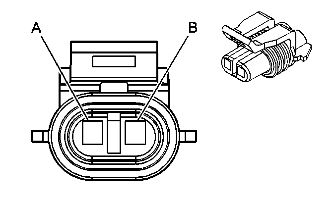
|
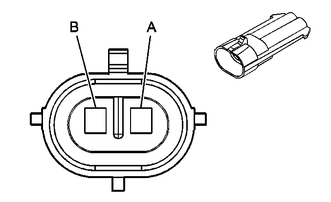
|
Connector Part Information
| Connector Part Information
|
Terminal Part Information
| Terminal Part Information
|
Pin | Wire Color | Circuit No. | Function | Pin | Wire Color | Circuit No. | Function |
|---|---|---|---|---|---|---|---|
A | 0.5 BN | 2609 | Right Rear Park Lamps Supply Voltage | A | 0.5 BN | 2609 | Right Rear Park Lamps Supply Voltage |
B | 0.5 BK | 1750 | Ground | B | 0.5 BK | 1750 | Ground |
X500 Left Front Door Harness to Body Harness (YE9 -AN3/DL3)
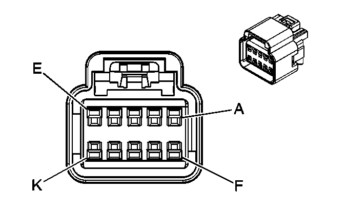
|
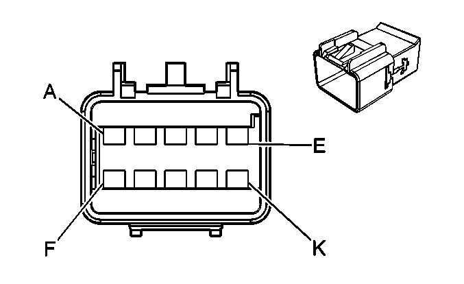
|
Connector Part Information
| Connector Part Information
|
Terminal Part Information
| Terminal Part Information
|
Pin | Wire Color | Circuit No. | Function | Pin | Wire Color | Circuit No. | Function |
|---|---|---|---|---|---|---|---|
A | 0.5 PU/WH | 889 | Passenger Mirror Motor Down Control (DL8/DPN) | A | 0.5 PU/WH | 889 | Passenger Mirror Motor Down Control (DL8/DPN) |
B | 0.5 TN/WH | 330 | Passenger Mirror Motor Supply Voltage (DL8/DPN) | B | 0.5 TN/WH | 330 | Passenger Mirror Motor Supply Voltage (DL8/DPN) |
C | 0.5 OG/WH | 881 | Passenger Mirror Motor Right Control (DL8/DPN) | C | 0.5 OG/WH | 881 | Passenger Mirror Motor Right Control (DL8/DPN) |
D | 0.5 WH | 2132 | Side Impact Sensing Module - Signal (ASF) | D | 0.5 WH | 2132 | Side Impact Sensing Module - Signal (ASF) |
E | 0.5 PU/WH | 6628 | Low Reference (ASF) | E | 0.5 PU/WH | 6628 | Low Reference (ASF) |
F | 0.35 PU | 171 | Power Window Master Switch Right Rear Down Signal (A31) | F | 0.35 PU | 171 | Power Window Master Switch Right Rear Down Signal (Crew Cab +31/Extended Cab +ABV) |
G | 0.35 L-GN | 170 | Power Window Master Switch Right Rear Up Signal (A31) | G | 0.35 L-GN | 170 | Power Window Master Switch Right Rear Up Signal (Crew Cab +31/Extended Cab +ABV) |
H | 0.35 YE | 43 | Accessory Voltage (A31) | H | 0.35 YE | 43 | Accessory Voltage |
J | 0.35 TN | 167 | Power Window Master Switch Right Front Down Signal (A31) | J | 0.35 TN | 167 | Power Window Master Switch Right Front Down Signal (A31) |
K | 0.5 OG | 2267 | Mirror Heating Element Supply Voltage (DL8/DPN) | K | 0.5 OG | 2267 | Mirror Heating Element Supply Voltage (DL8/DPN) |
X501 Left Front Door Harness to Body Harness (YE9 -AN3/DL3)

|

|
Connector Part Information
| Connector Part Information
|
Terminal Part Information
| Terminal Part Information
|
Pin | Wire Color | Circuit No. | Function | Pin | Wire Color | Circuit No. | Function |
|---|---|---|---|---|---|---|---|
A | 0.35 L-BU | 166 | Power Window Master Switch Right Front Up Signal (A31) | A | 0.35 L-BU | 166 | Power Window Master Switch Right Front Up Signal (A31) |
B | 0.35 PU | 169 | Power Window Master Switch Left Rear Down Signal (Crew Cab +A31/Extended Cab +ABV) | B | 0.35 PU | 169 | Power Window Master Switch Left Rear Down Signal (Crew Cab +A31/Extended Cab +ABV) |
C | 0.35 D-GN | 168 | Power Window Master Switch Left Rear Up Signal (Crew Cab +A31/Extended Cab +ABV) | C | 0.35 D-GN | 168 | Power Window Master Switch Left Rear Up Signal (Crew Cab +A31/Extended Cab +ABV) |
D | 0.35 D-BU | 1307 | Power Window Master Switch Lockout Signal (Crew Cab +A31/Extended Cab +ABV) | D | 0.35 D-BU | 1307 | Power Window Master Switch Lockout Signal (Crew Cab +A31/Extended Cab +ABV) |
E | 0.35 L-BU/WH | 280 | Power Window Master Switch Lockout Right Rear Signal (Crew Cab +A31/Extended Cab +ABV) | E | 0.35 L-BU/WH | 280 | Power Window Master Switch Lockout Right Rear Signal (Crew Cab +A31/Extended Cab +ABV) |
F | 0.8 GY | 295 | Door Lock Actuator Lock Control (AU3) | F | 0.8 GY | 295 | Door Lock Actuator Lock Control (AU3) |
G | 0.8 TN | 694 | Driver Door Lock Actuator Unlock Control (AU3) | G | 0.8 TN | 694 | Driver Door Lock Actuator Unlock Control (AU3) |
H | 0.35 OG/BK | 781 | Driver Door Lock Switch Unlock Signal (AU3) | H | 0.35 OG/BK | 781 | Driver Door Lock Switch Unlock Signal (AU3) |
J | 0.35 PK/BK | 780 | Driver Door Lock Switch Lock Signal (AU3) | J | 0.35 PK/BK | 780 | Driver Door Lock Switch Lock Signal |
K | 0.35 L-GN | 262 | Driver Door Key Switch Signal (AU3) | K | 0.35 L-GN | 262 | Driver Door Key Switch Signal |
X502 Left Front Door Harness to Body Harness (ASF+AN3/-YE9)
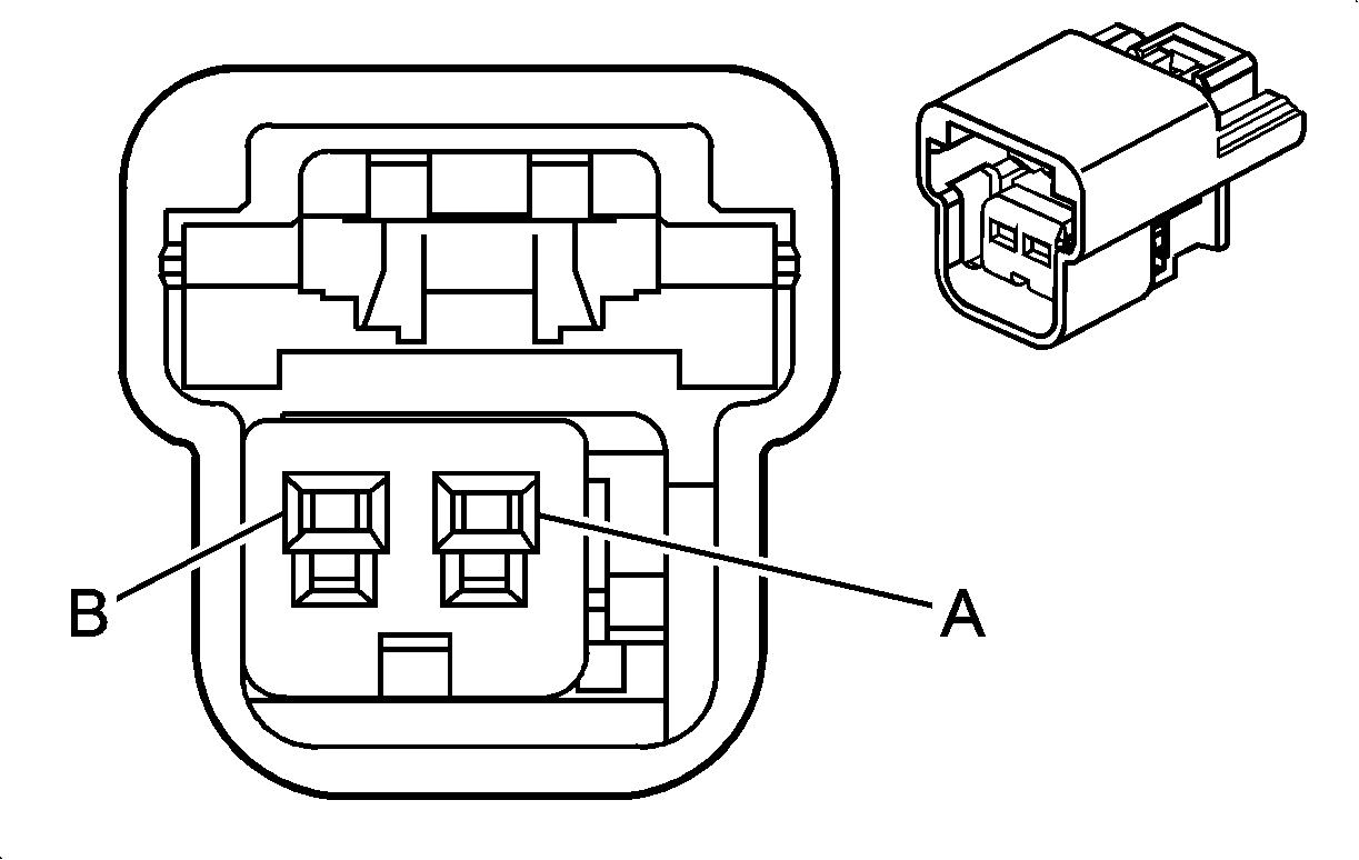
|
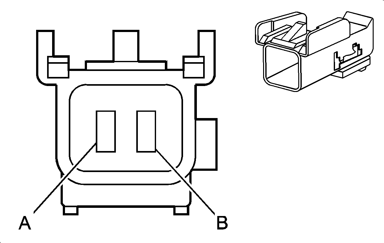
|
Connector Part Information
| Connector Part Information
|
Terminal Part Information
| Terminal Part Information
|
Pin | Wire Color | Circuit No. | Function | Pin | Wire Color | Circuit No. | Function |
|---|---|---|---|---|---|---|---|
A | 0.5 PU/WH | 6628 | Low Reference | A | 0.5 PU/WH | 6628 | Low Reference |
B | 0.5 WH | 2132 | Left Front Side Impact Sensing Module Signal | B | 0.5 WH | 2132 | Left Front Side Impact Sensing Module Signal |
X600 Right Front Door Harness to Body Harness (YE9 -AN3/DL3)

|

|
Connector Part Information
| Connector Part Information
|
Terminal Part Information
| Terminal Part Information
|
Pin | Wire Color | Circuit No. | Function | Pin | Wire Color | Circuit No. | Function |
|---|---|---|---|---|---|---|---|
A | 0.5 OG | 2267 | Mirror Heating Element Supply Voltage (DL8/DPN) | A | 0.5 OG | 2267 | Mirror Heating Element Supply Voltage (DL8/DPN) |
B | -- | -- | Not Used | B | -- | -- | Not Used |
C | 0.35 YE | 43 | Accessory Voltage (A31) | C | 0.35 YE | 43 | Accessory Voltage |
D | 0.5 PU/WH | 889 | Passenger Mirror Motor Down Control (DL8/DPN) | D | 0.5 PU/WH | 889 | Passenger Mirror Motor Down Control (DL8/DPN) |
E | 0.5 TN/WH | 330 | Passenger Mirror Motor Supply Voltage (DL8/DPN) | E | 0.5 TN/WH | 330 | Passenger Mirror Motor Supply Voltage (DL8/DPN) |
F | 0.5 OG/WH | 881 | Passenger Mirror Motor Right Control (DL8/DPN) | F | 0.5 OG/WH | 881 | Passenger Mirror Motor Right Control (DL8/DPN) |
G | 0.35 TN | 167 | Power Window Master Switch Right Front Down Signal (A31) | G | 0.35 TN | 167 | Power Window Master Switch Right Front Down Signal (A31) |
H | 0.35 L-BU | 166 | Power Window Master Switch Right Front Up Signal (A31) | H | 0.35 L-BU | 166 | Power Window Master Switch Right Front Up Signal (A31) |
J | 0.35 L-BU | 244 | Passenger Door Lock Switch Lock Signal (AU3) | J | 0.35 L-BU | 244 | Passenger Door Lock Switch Lock Signal (AU3) |
K | 0.35 D-BU | 245 | Passenger Door Lock Switch Unlock Signal (AU3) | K | 0.35 D-BU | 245 | Passenger Door Lock Switch Unlock Signal (AU3) |
X601 Right Front Door Harness to Body Harness (ASF)

|

|
Connector Part Information
| Connector Part Information
|
Terminal Part Information
| Terminal Part Information
|
Pin | Wire Color | Circuit No. | Function | Pin | Wire Color | Circuit No. | Function |
|---|---|---|---|---|---|---|---|
A | 0.5 WH/WH | 6629 | Low Reference | A | 0.5 WH/BK | 6629 | Low Reference |
B | 0.5 D-GN | 2134 | Right Front Side Impact Sensing Module Signal | B | 0.5 D-GN | 2134 | Right Front Side Impact Sensing Module Signal |
X700 Body Harness to Left Rear Door Harness (Crew Cab)
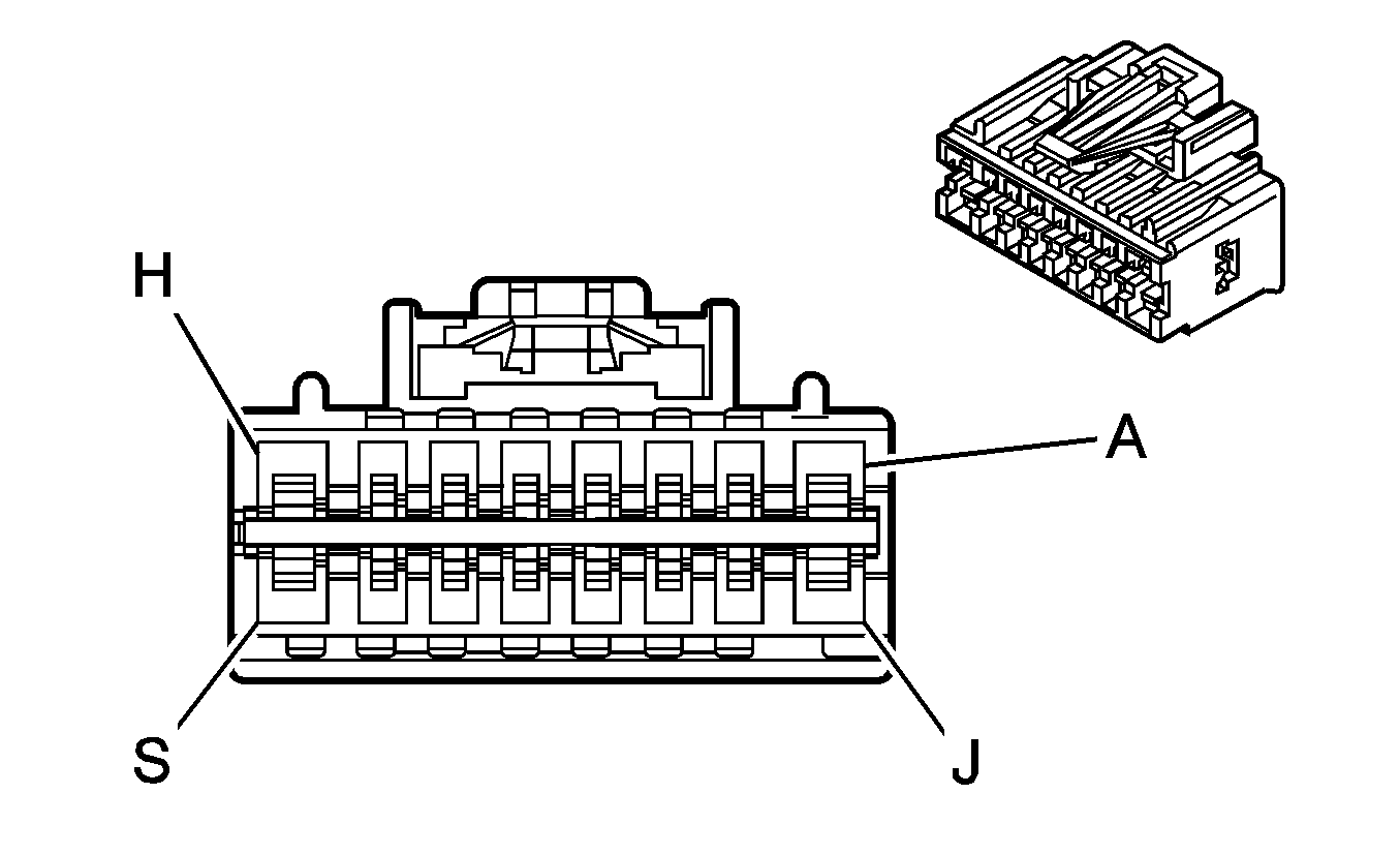
|
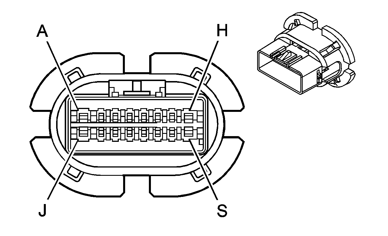
|
Connector Part Information
| Connector Part Information
|
Terminal Part Information
| Terminal Part Information
|
Pin | Wire Color | Circuit No. | Function | Pin | Wire Color | Circuit No. | Function |
|---|---|---|---|---|---|---|---|
A | 2 BK | 1150 | Ground | A | 3 BK | 1150 | Ground |
B | 0.35 PU | 169 | Power Window Master Switch Left Rear Down Signal | B | 0.35 PU | 169 | Power Window Master Switch Left Rear Down Signal |
C | 0.35 D-BU | 1307 | Power Window Master Switch Lockout Signal | C | 0.35 D-BU | 1307 | Power Window Master Switch Lockout Signal |
D | 0.35 D-GN | 168 | Power Window Master Switch Left Rear Up Signal | D | 0.35 D-GN | 168 | Power Window Master Switch Left Rear Up Signal |
E | 0.5 BN/WH | 230 | Instrument Panel Lamps Dimming Control | E | 0.5 BN/WH | 230 | Instrument Panel Lamps Dimming Control |
F | 0.35 L-BU/BK | 747 | Left Rear Door Ajar Switch Signal | F | 0.35 L-BU/BK | 747 | Left Rear Door Ajar Switch Signal |
G | 0.5 L-GN/BK | 6623 | Low Reference (ASF) | G | 0.5 L-GN/BK | 6623 | Low Reference (ASF) |
H | 2 RD/WH | 1240 | Battery Positive Voltage | H | 3 RD/WH | 1240 | Battery Positive Voltage |
J | -- | -- | Not Used | J | -- | -- | Not Used |
K | 0.8 YE | 116 | Left Rear Speaker Output (-) | K | 0.8 YE | 116 | Left Rear Speaker Output (-) |
L | 0.8 BN | 199 | Left Rear Speaker Output (+) | L | 0.8 BN | 199 | Left Rear Speaker Output (+) |
M | 0.5 BK | 1150 | Ground | M | 0.35 BK | 1150 | Ground |
N | 0.8 TN | 294 | Door Lock Actuator Unlock Control | N | 0.8 TN | 294 | Door Lock Actuator Unlock Control |
P | 0.8 GY | 295 | Door Lock Actuator Lock Control | P | 0.8 GY | 295 | Door Lock Actuator Lock Control |
R | 0.5 L-BU | 6622 | Left Rear Side Impact Sensing Module Signal (ASF) | R | 0.5 L-BU | 6622 | Left Rear Side Impact Sensing Module Signal (ASF) |
S | 0.35 OG | 5922 | Non-Driver Door Open Switch Signal | S | 0.35 OG | 5922 | Non-Driver Door Open Switch Signal |
0.35 OG | 5922 | Non-Driver Door Open Switch Signal (AN3) |
X700 Left Rear Door Harness to Body Harness (Extended Cab)
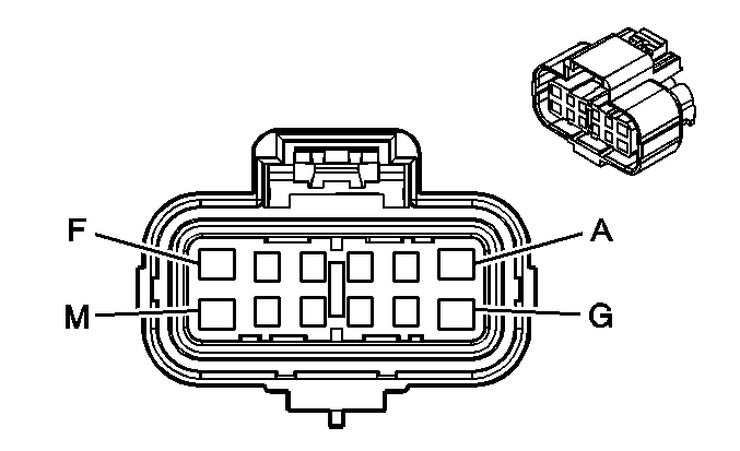
|
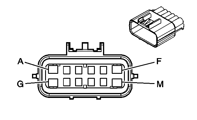
|
Connector Part Information
| Connector Part Information
|
Terminal Part Information
| Terminal Part Information
|
Pin | Wire Color | Circuit No. | Function | Pin | Wire Color | Circuit No. | Function |
|---|---|---|---|---|---|---|---|
A | 3 BK | 1150 | Ground | A | 2 BK | 1150 | Ground |
B | 0.35 PU | 169 | Power Window Master Switch Left Rear Down Signal | B | 0.35 PU | 169 | Power Window Master Switch Left Rear Down Signal |
C | 0.35 D-BU | 1307 | Power Window Master Switch Lockout Signal | C | 0.35 D-BU | 1307 | Power Window Master Switch Lockout Signal |
D | 0.35 D-GN | 168 | Power Window Master Switch Left Rear Up Signal | D | 0.35 D-GN | 168 | Power Window Master Switch Left Rear Up Signal |
E | 0.5 BN/WH | 230 | Instrument Panel Lamps Dimming Control | E | 0.5 BN/WH | 230 | Instrument Panel Lamps Dimming Control |
F | 3 RD/WH | 1240 | Battery Positive Voltage | F | 2 RD/WH | 1240 | Battery Positive Voltage |
G | 0.5 L-GN/BK | 6623 | Low Reference (ASF) | G | 0.5 L-GN/BK | 6623 | Low Reference (ASF) |
H | 0.5 L-BU | 6622 | Left Rear Side Impact Sensing Module Signal (ASF) | H | 0.5 L-BU | 6622 | Left Rear Side Impact Sensing Module Signal (ASF) |
J | -- | -- | Not Used | J | -- | -- | Not Used |
K | 0.8 BN | 199 | Left Rear Speaker Output (+) | K | 0.8 BN | 199 | Left Rear Speaker Output (+) |
L | 0.8 YE | 116 | Left Rear Speaker Output (-) | L | 0.8 YE | 116 | Left Rear Speaker Output (-) |
M | -- | -- | Not Used | M | -- | -- | Not Used |
X800 Body Harness to Right Rear Door Harness (Crew Cab)

|

|
Connector Part Information
| Connector Part Information
|
Terminal Part Information
| Terminal Part Information
|
Pin | Wire Color | Circuit No. | Function | Pin | Wire Color | Circuit No. | Function |
|---|---|---|---|---|---|---|---|
A | 2 BK | 1250 | Ground | A | 3 BK | 1250 | Ground |
B | 0.35 PU | 171 | Power Window Master Switch Right Rear Down Signal | B | 0.35 PU | 171 | Power Window Master Switch Right Rear Down Signal |
C | 0.35 L-BU/WH | 280 | Power Window Master Switch Lockout Right Rear Signal | C | 0.35 L-BU/WH | 280 | Power Window Master Switch Lockout Right Rear Signal |
D | 0.35 L-GN | 170 | Power Window Master Switch Right Rear Up Signal | D | 0.35 L-GN | 170 | Power Window Master Switch Right Rear Up Signal |
E | 0.5 BN/WH | 230 | Instrument Panel Lamps Dimming Control | E | 0.5 BN/WH | 230 | Instrument Panel Lamps Dimming Control |
F | 0.35 L-GN/BK | 748 | Right Rear Door Ajar Switch Signal | F | 0.35 L-GN/BK | 748 | Right Rear Door Ajar Switch Signal |
G | 0.5 PK/BK | 6627 | Low Reference (ASF) | G | 0.5 PK/BK | 6627 | Low Reference (ASF) |
H | 2 RD/WH | 1340 | Battery Positive Voltage | H | 3 RD/WH | 1340 | Battery Positive Voltage |
J | -- | -- | Not Used | J | -- | -- | Not Used |
K | 0.8 L-BU | 115 | Right Rear Speaker Output (-) | K | 0.8 L-BU | 115 | Right Rear Speaker Output (-) |
L | 0.8 D-BU | 46 | Right Rear Speaker Output (+) | L | 0.8 D-BU | 46 | Right Rear Speaker Output (+) |
M | 0.5 BK | 1250 | Ground | M | 0.35 BK | 1250 | Ground |
N | 0.8 TN | 294 | Door Lock Actuator Unlock Control | N | 0.8 TN | 294 | Door Lock Actuator Unlock Control |
P | 0.8 GY | 295 | Door Lock Actuator Lock Control | P | 0.8 GY | 295 | Door Lock Actuator Lock Control |
R | 0.5 L-BU/WH | 6626 | Right Rear Side Impact Sensing Module Signal (ASF) | R | 0.5 L-BU/WH | 6626 | Right Rear Side Impact Sensing Module Signal (ASF) |
S | 0.35 OG | 5922 | Non-Driver Door Open Switch Signal | S | 0.35 OG | 5922 | Non-Driver Door Open Switch Signal |
0.35 OG | 5922 | Non-Driver Door Open Switch Signal (Crew Cab +AN3) |
X800 Right Rear Door Harness to Body Harness (Extended Cab)

|

|
Connector Part Information
| Connector Part Information
|
Terminal Part Information
| Terminal Part Information
|
Pin | Wire Color | Circuit No. | Function | Pin | Wire Color | Circuit No. | Function |
|---|---|---|---|---|---|---|---|
A | 3 BK | 1250 | Ground | A | 2 BK | 1250 | Ground |
B | 0.35 PU | 171 | Power Window Master Switch Right Rear Down Signal | B | 0.35 PU | 171 | Power Window Master Switch Right Rear Down Signal |
C | 0.35 L-BU/WH | 280 | Power Window Master Switch Lockout Right Rear Signal | C | 0.35 L-BU/WH | 280 | Power Window Master Switch Lockout Right Rear Signal |
D | 0.35 L-GN | 170 | Power Window Master Switch Right Rear Up Signal | D | 0.35 L-GN | 170 | Power Window Master Switch Right Rear Up Signal |
E | 0.5 BN/WH | 230 | Instrument Panel Lamps Dimming Control | E | 0.5 BN/WH | 230 | Instrument Panel Lamps Dimming Control |
F | 3 RD/WH | 1340 | Battery Positive Voltage | F | 2 RD/WH | 1340 | Battery Positive Voltage |
G | 0.5 PK/BK | 6627 | Low Reference (ASF) | G | 0.5 PK/BK | 6627 | Low Reference (ASF) |
H | 0.5 L-BU/WH | 6626 | Right Rear Side Impact Sensing Module Signal (ASF) | H | 0.5 L-BU/WH | 6626 | Right Rear Side Impact Sensing Module Signal (ASF) |
J | -- | -- | Not Used | J | -- | -- | Not Used |
K | 0.8 D-BU | 46 | Right Rear Speaker Output (+) | K | 0.8 D-BU | 46 | Right Rear Speaker Output (+) |
L | 0.8 L-BU | 115 | Right Rear Speaker Output (-) | L | 0.8 L-BU | 115 | Right Rear Speaker Output (-) |
M | -- | -- | Not Used | M | -- | -- | Not Used |
