Tools Required
J 43909
Manual Shift Shaft Seal Installer
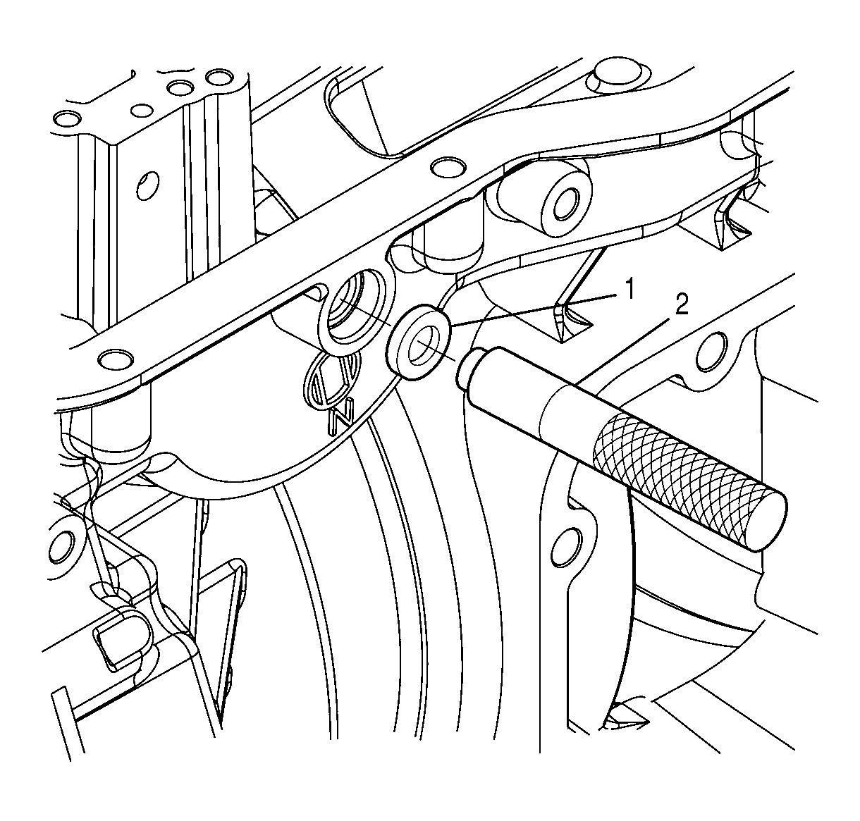
- Install a new manual shift shaft seal (1) onto
J 43909
(2).
- Using
J 43909
(2) , drive the manual shift shaft seal (1) into the transmission case.
- Make sure the manual shift shaft seal is seated on the bottom of the bore.
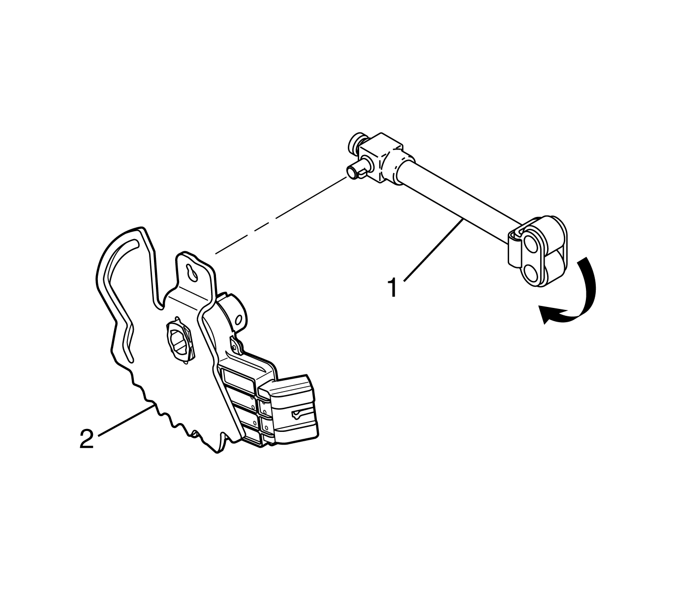
- Install the nib of the park pawl assembly (1)
through the keyhole in the detent lever/internal mode switch (IMS) assembly (2).
- Rotate the park pawl assembly 180 degrees.
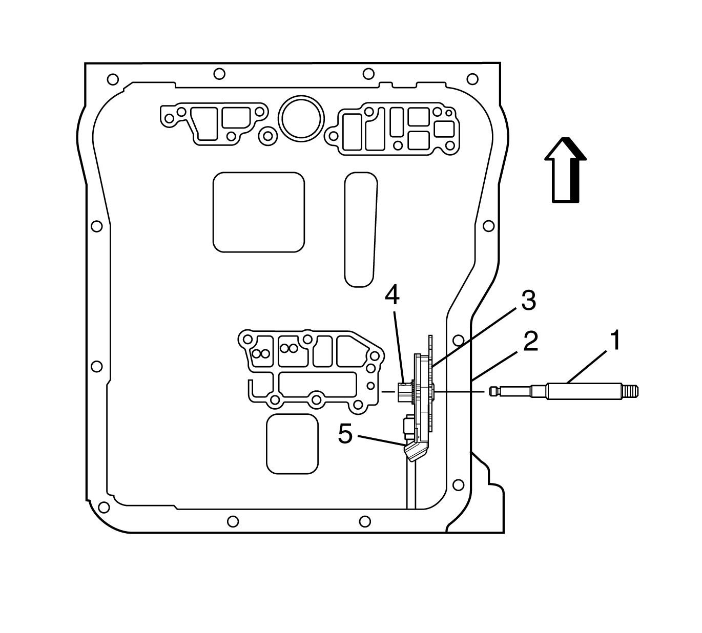
- Place the roller end of the park pawl assembly (5)
into the transmission case.
- Align the detent lever/IMS assembly (3) so that:
| • | The detent notches of the detent lever are facing up. |
| • | The IMS connector is facing towards the rear of the transmission. |
| • | The guide hole for the manual valve pin is facing forward. |
| • | The manual shift shaft hole in the detent lever is aligned with the manual shift shaft seal (2). |
- Slide the manual shift shaft (1) through the following components:
| • | Manual shift shaft seal (2) |
| • | Detent lever/IMS assembly (3) |
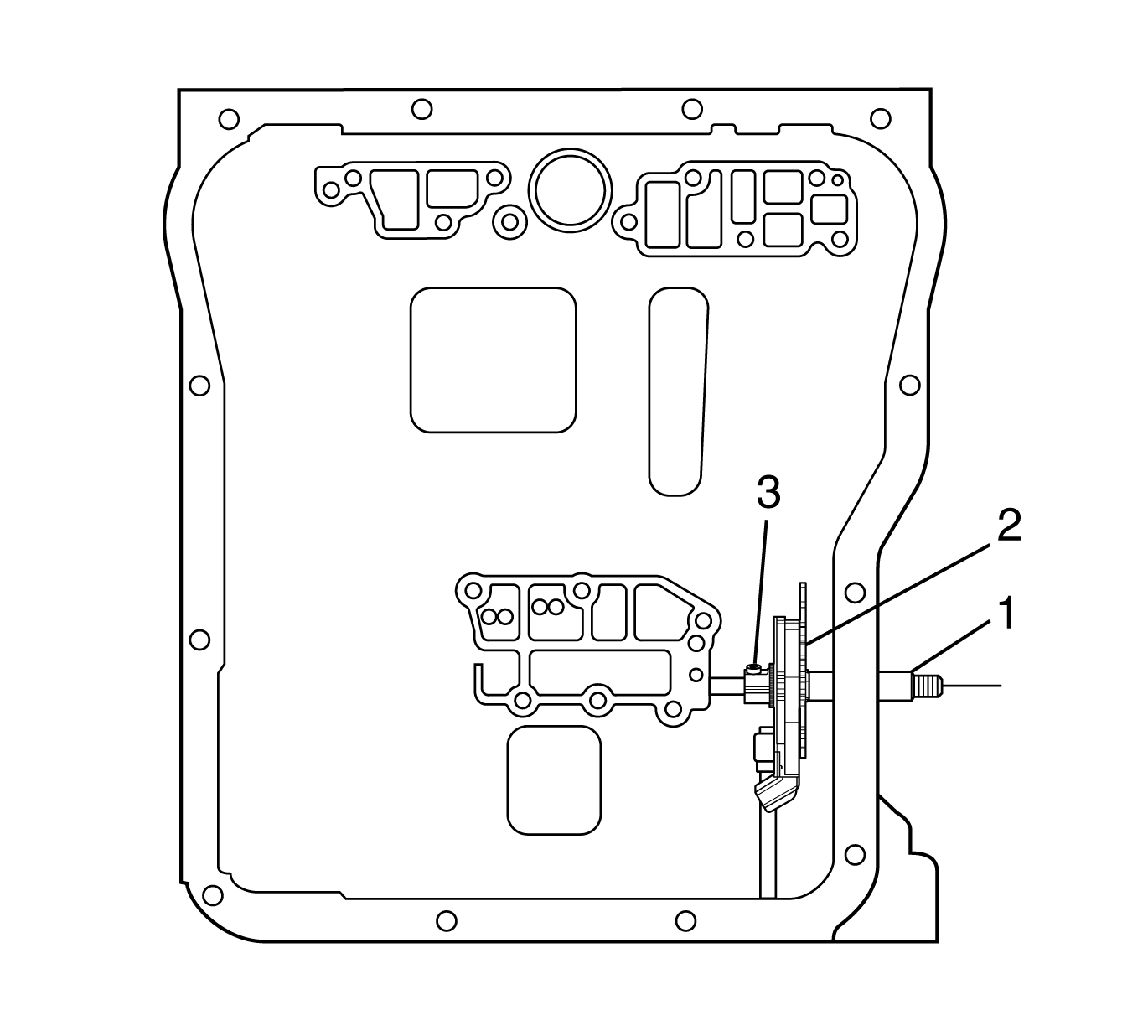
Important: The detent lever/IMS assembly retaining bolt contains patch lock material on the threads. Do not reuse the retaining bolt.
- Install the detent lever/IMS assembly (2) onto the manual shift shaft (1).
- Install the detent lever/IMS assembly retaining bolt (3).
Notice: Refer to Fastener Notice in the Preface section.
- Using a T27 Torx® bit, tighten the detent lever/IMS assembly retaining bolt (3).
Tighten
Tighten the bolt to 10 N·m (89 lb in).
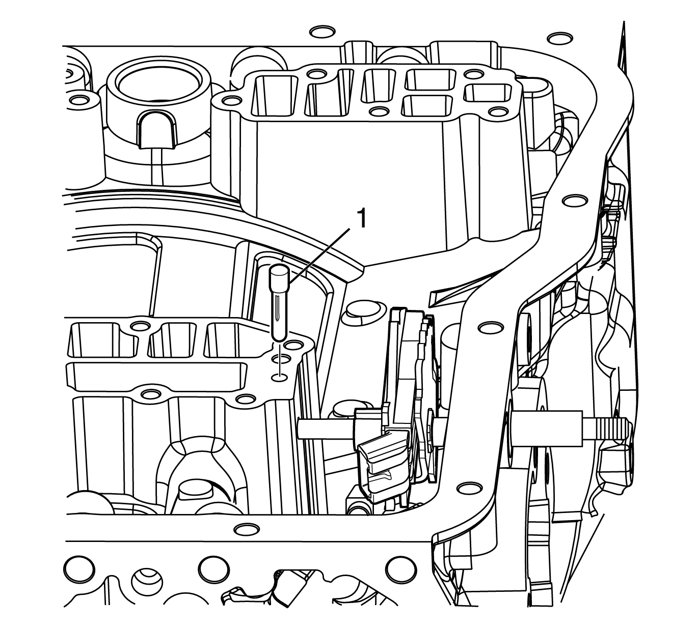
Notice: DO NOT mar the transmission case surface around the
spherical pin when removing or installing the spherical pin. An unmarred surface is required to maintain the seal between the control valve assembly and the transmission case.
- Install the spherical pin (1) into the transmission case.
- Lightly tap the spherical pin (1) into position until the head of the pin (1) is seated against the transmission case.


