Removal Procedure
Note:
| • | The intake manifold may be removed as an assembly. Do not remove the specific intake manifold components unless component service is required. |
| • | It is not necessary to remove the upper intake manifold in order to remove the lower intake manifold. |
| • | Do not allow dirt or debris to enter the fuel system. Ensure that the ends of the fuel system are properly sealed. |
| • | Do not disassemble the central sequential fuel injection (SFI) unit, unless service is required. |
- Drain the cooling system. Refer to
Cooling System Draining and Filling.
- Remove the fuel pipes/hoses. Refer to
Fuel Hose/Pipes Replacement - Engine Compartment.
- Remove the ignition coil assembly. Refer to
Ignition Coil Replacement.
- Remove the evaporative emission (EVAP) canister tube. Refer to
Evaporative Emission Hoses/Pipes Replacement - Engine.
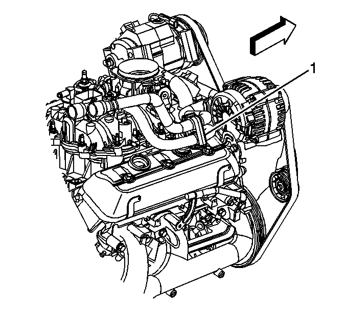
- Remove the heater hose clamp (1).
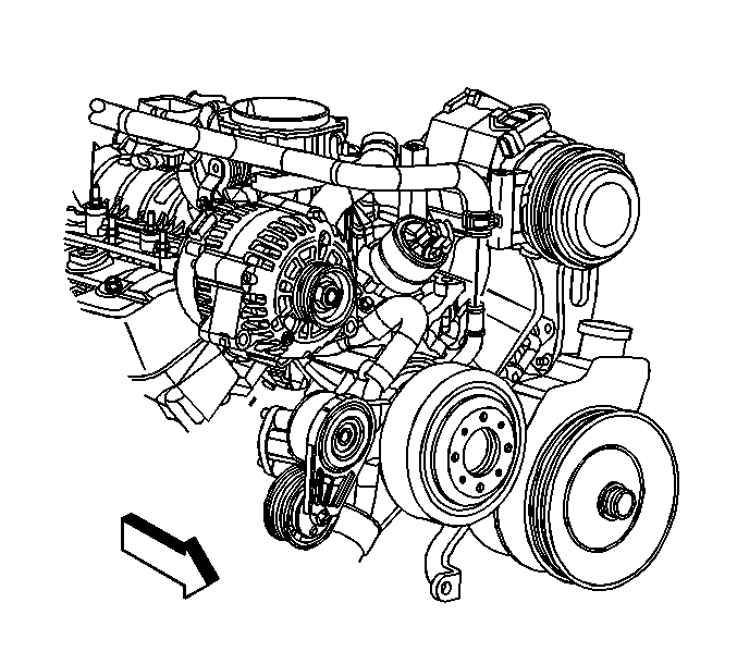
- Open the heater outlet hose clamp and remove the hose from the intake manifold.
- Open the heater inlet hose clamp and remove the hose from the water pump.
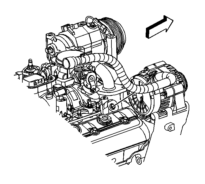
- Reposition the heater inlet and outlet hoses.
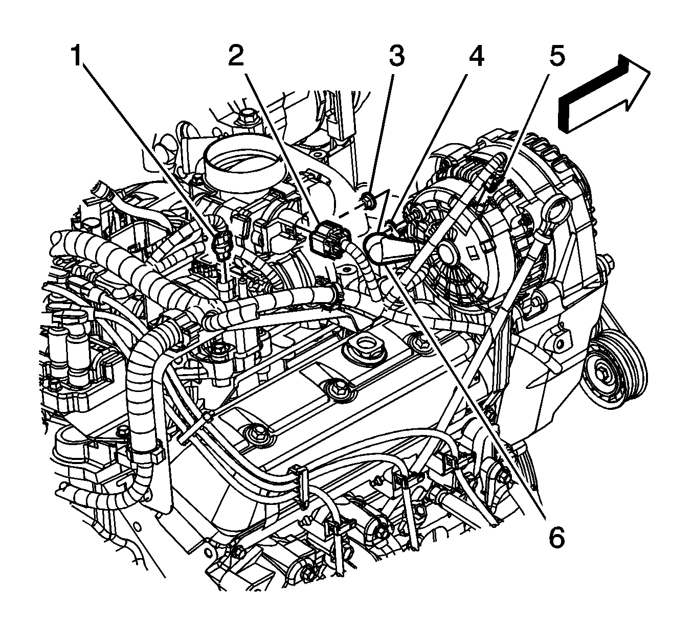
- Disconnect the engine wiring harness electrical connector (2) from the throttle body.
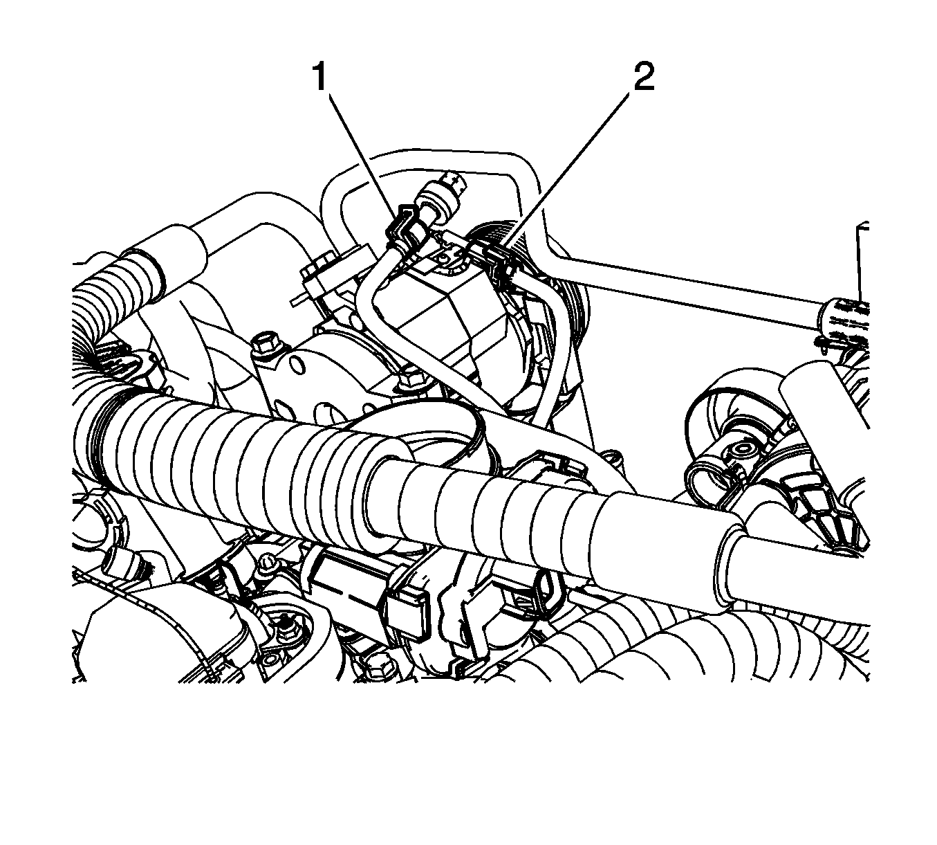
- Disconnect the following electrical connectors:
| • | The A/C pressure switch (1), if equipped |
| • | The air conditioning (A/C) compressor clutch (2), if equipped |
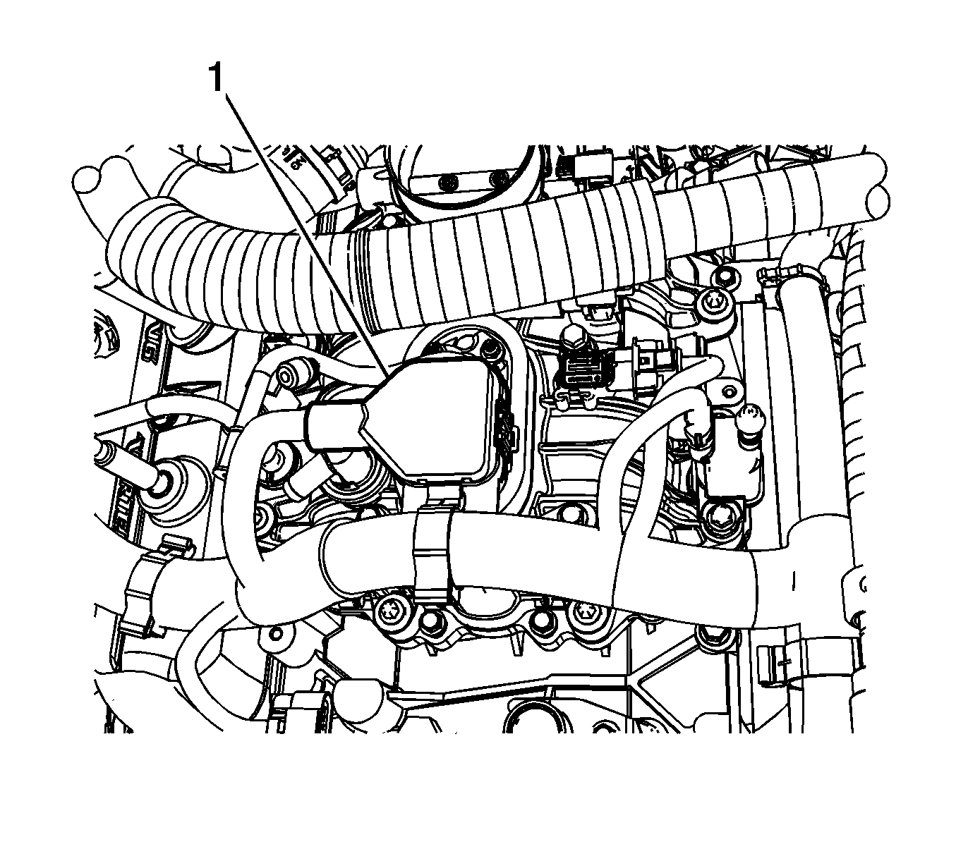
- Disconnect the control port injector module (1).

- Disconnect the following electrical connectors:
| • | The EVAP canister purge solenoid valve (1) |
| • | The manifold absolute pressure (MAP) sensor |
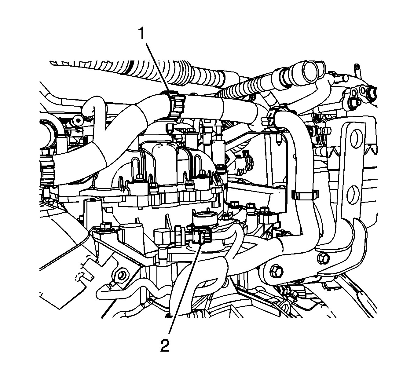
- Remove the engine harness clamp (1) from the bracket.
- Disconnect the oil pressure sensor electrical connector (2).
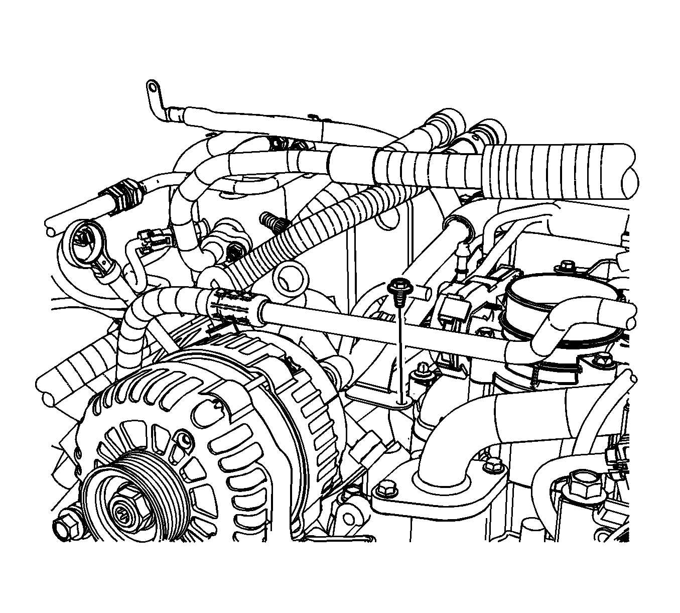
- Remove the engine wiring harness bracket bolt (1).
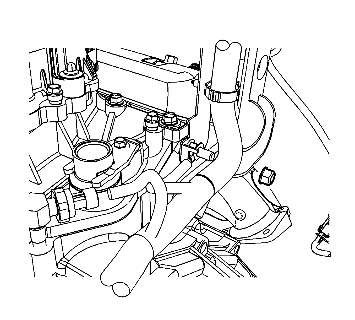
- Remove the engine wiring harness ground nut and ground wire (1) from the rear of the right cylinder head.
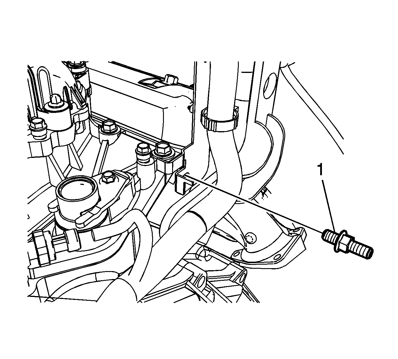
- Remove the stud (1) holding the engine wiring harness bracket.
- Reposition the engine wiring harness with the bracket aside.
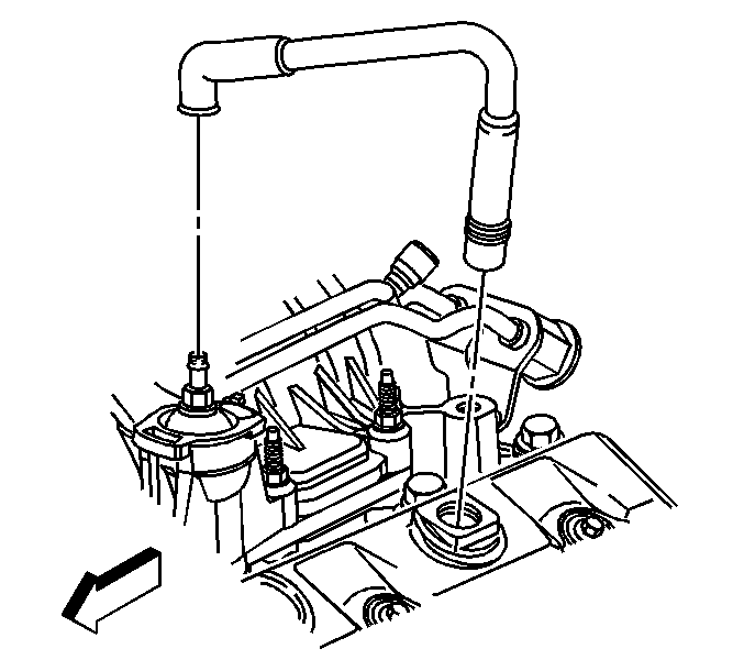
- Remove the positive crankcase ventilation (PCV) valve hose from the valve cover and rocker cover.
- Disconnect the power brake booster vacuum hose from the vacuum fitting.
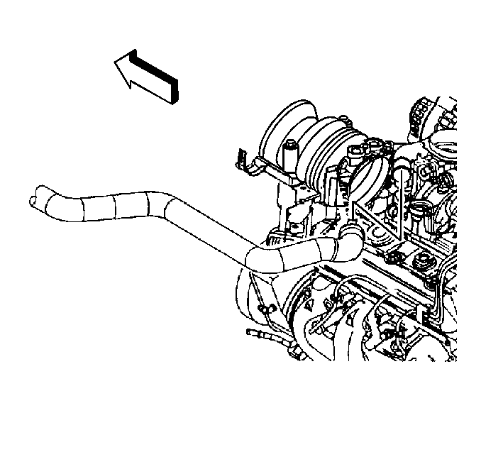
- Reposition the radiator inlet hose clamps.
- Remove the radiator inlet hose from the thermostat housing.
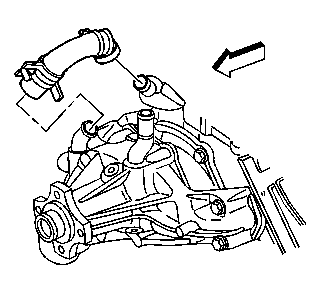
- Reposition the water pump inlet hose clamps.
- Remove the water pump inlet hose.
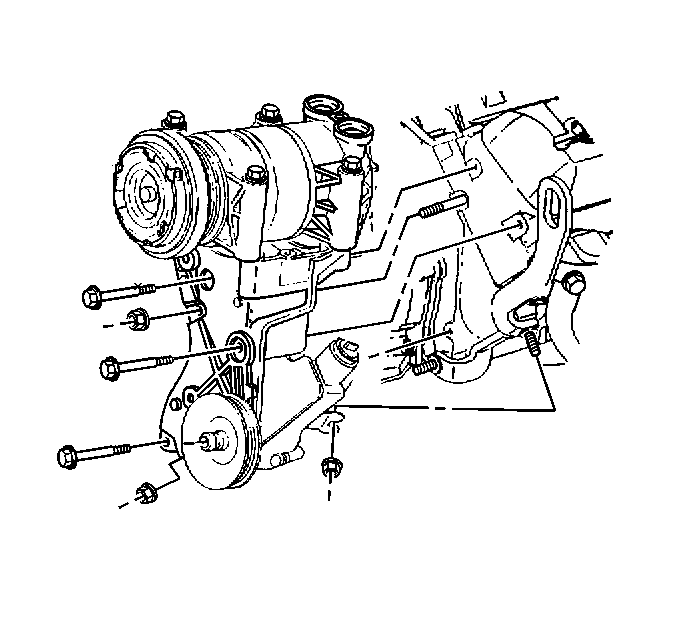
- In order to remove the front intake manifold bolt, perform the following:
| 25.2. | Loosen the power steering (P/S) pump rear bracket nut. |
| 25.3. | Remove the P/S pump rear bracket front nut. |
| 25.4. | Remove the bolts and the nut for the P/S pump bracket. |
| 25.5. | Leave the A/C compressor, if equipped, and the P/S pump on the bracket. |
| 25.6. | Slide the P/S pump bracket forward to access the front intake manifold bolt. |
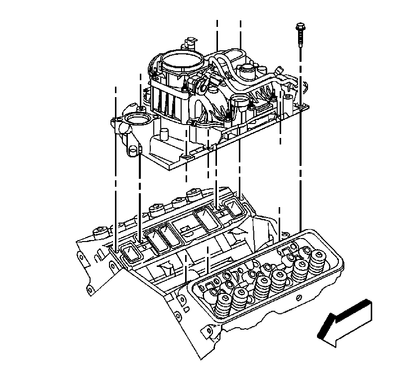
- Remove the intake manifold - lower bolts.
- Remove the intake manifold.
- Remove and discard the intake manifold gaskets.
- Clean and inspect the intake manifold - lower, if necessary. Refer to
Intake Manifold Cleaning and Inspection.
Installation Procedure
Caution: Apply the proper amount of the sealant when assembling this component. Excessive use of the sealant can prohibit the component from sealing properly. A component that is not sealed properly
can leak leading to extensive engine damage.
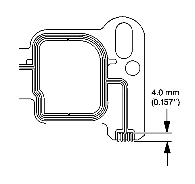
- Apply a 4.0 mm (0.157 in) patch of adhesive to the cylinder head side of the intake manifold gasket at each end. Refer to
Adhesives, Fluids, Lubricants, and Sealers for the correct part number.
Note: The intake manifold gasket must be installed while the adhesive is still wet to the touch.
- Install the intake manifold gasket onto the cylinder head. Use the gasket locating pins in order to properly seat the gasket.
Note: The intake manifold must be installed and the fasteners tightened while the adhesive is still wet to the touch.
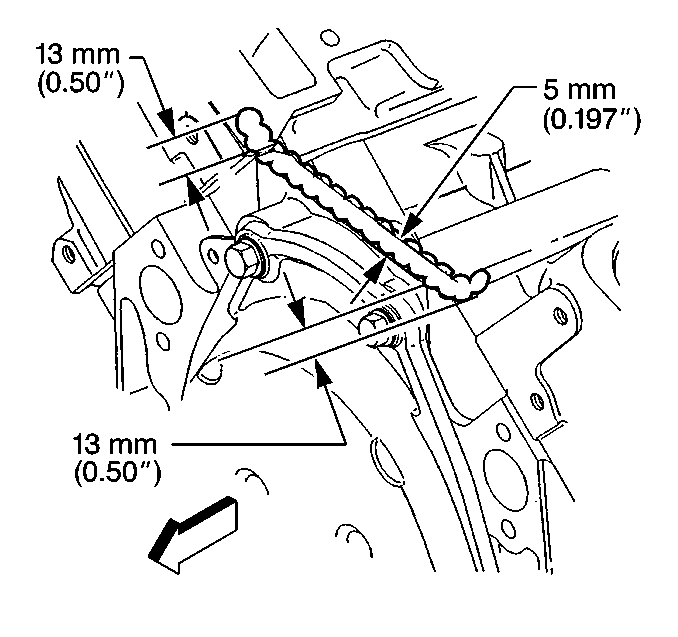
- Apply a 5 mm (0.197 in) bead of adhesive to the front top of the engine block. Refer to
Adhesives, Fluids, Lubricants, and Sealers for the correct part number.
- Extend the adhesive bead 13 mm (0.50 in) up onto each intake manifold gasket.
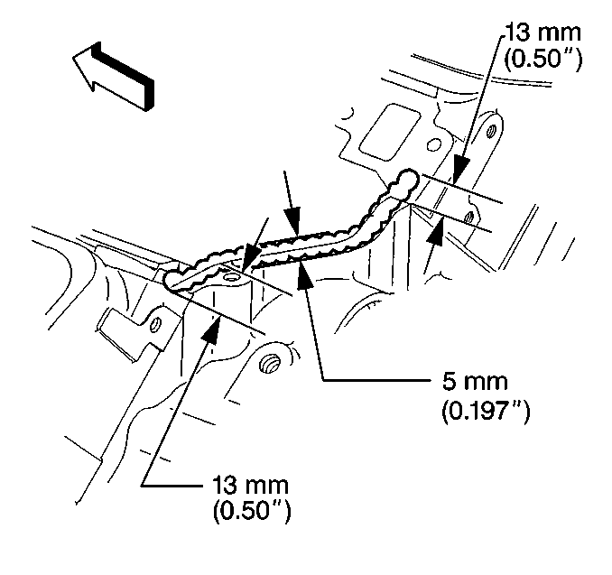
- Apply a 5 mm (0.197 in) bead of adhesive to the rear top of the engine block. Refer to
Adhesives, Fluids, Lubricants, and Sealers for the correct part number.
- Extend the adhesive bead 13 mm (0.50 in) up onto each intake manifold gasket.

- Install the intake manifold.
- If reusing the old fasteners, apply threadlock to the threads of the intake manifold - lower bolts. Refer to
Adhesives, Fluids, Lubricants, and Sealers for the correct part number.
- Install the intake manifold - lower bolts.
Caution: Refer to Fastener Caution in the Preface section.
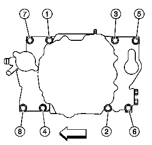
Caution: Proper lower intake manifold fastener tightening sequence and torque is critical. Always follow the tightening sequence, and torque the intake manifold bolts using the 3 step method. Failing to
do so may distort the crankshaft bearing bore alignment and cause damage to the crankshaft bearings.
- Tighten the intake manifold - lower bolts in the sequence shown.
Tighten
- Tighten the bolts a first pass to 3 N·m (27 lb in).
- Tighten the bolts a second pass to 12 N·m (106 lb in).
- Tighten the bolts a final pass to 15 N·m (11 lb ft).

- Slide the P/S pump bracket rearward.
- Install the bolts and the nut for the P/S pump bracket.
- Install the P/S pump rear bracket front nut.
- Tighten the P/S pump rear bracket nut.
Tighten
Tighten the bolts and nuts to 41 N·m (30 lb ft).
- Install the drive belt. Refer to
Drive Belt Replacement.

- Install the water pump inlet hose.
- Position the water pump inlet hose clamps.

- Install the radiator inlet hose to the thermostat housing.
- Position the radiator inlet hose clamps.
- Connect the power brake booster vacuum hose to the vacuum fitting.

- Install the PCV valve hose to the valve cover and rocker cover.

- Position the engine wiring harness and bracket.
- Install the engine wiring harness bracket stud (1).
Tighten
Tighten the stud to 25 N·m (18 lb ft).
- Install the engine wiring harness rear bracket nut at the EVAP canister purge solenoid valve.
Tighten
Tighten the nut to 9 N·m (80 lb in).

- Install the engine wiring harness ground nut and ground wire (1) to the rear of the right cylinder head.
Tighten
Tighten the nut to 16 N·m (12 lb ft).

- Install the engine wiring harness bracket bolt (1).
Tighten
Tighten the bolt to 12 N·m (106 lb in).
- Install the EVAP canister tube. Refer to
Evaporative Emission Hoses/Pipes Replacement - Engine.

- Connect the oil pressure sensor electrical connector (2).
- Install the engine harness clamp (1) to the bracket.

- Connect the following electrical connectors:
| • | The EVAP canister purge solenoid valve (1) |

- Connect the control port injector module (1).

- Connect the following electrical connectors:
| • | The A/C compressor clutch (2), if equipped |
| • | The A/C pressure switch (1), if equipped |

- Connect the engine wiring harness electrical connector (2) to the throttle body.

- Position the heater inlet and outlet hoses.
- Open the heater inlet hose clamp and install the hose to the water pump.

- Open the heater outlet hose clamp and install the hose to the intake manifold.

- Install the heater hose clamp (1).
- Install the fuel pipes/hoses. Refer to
Fuel Hose/Pipes Replacement - Engine Compartment.
- Install the ignition coil assembly. Refer to
Ignition Coil Replacement.
- Fill the cooling system. Refer to
Cooling System Draining and Filling.


