For 1990-2009 cars only
Special Tools
J 7872 Dial Indicator Set
For equivalent regional tools, refer to Special Tools.
- Install the camshaft thrust plate to the camshaft.
- Install the camshaft driven gear.
- Install a new camshaft driven gear bolt.
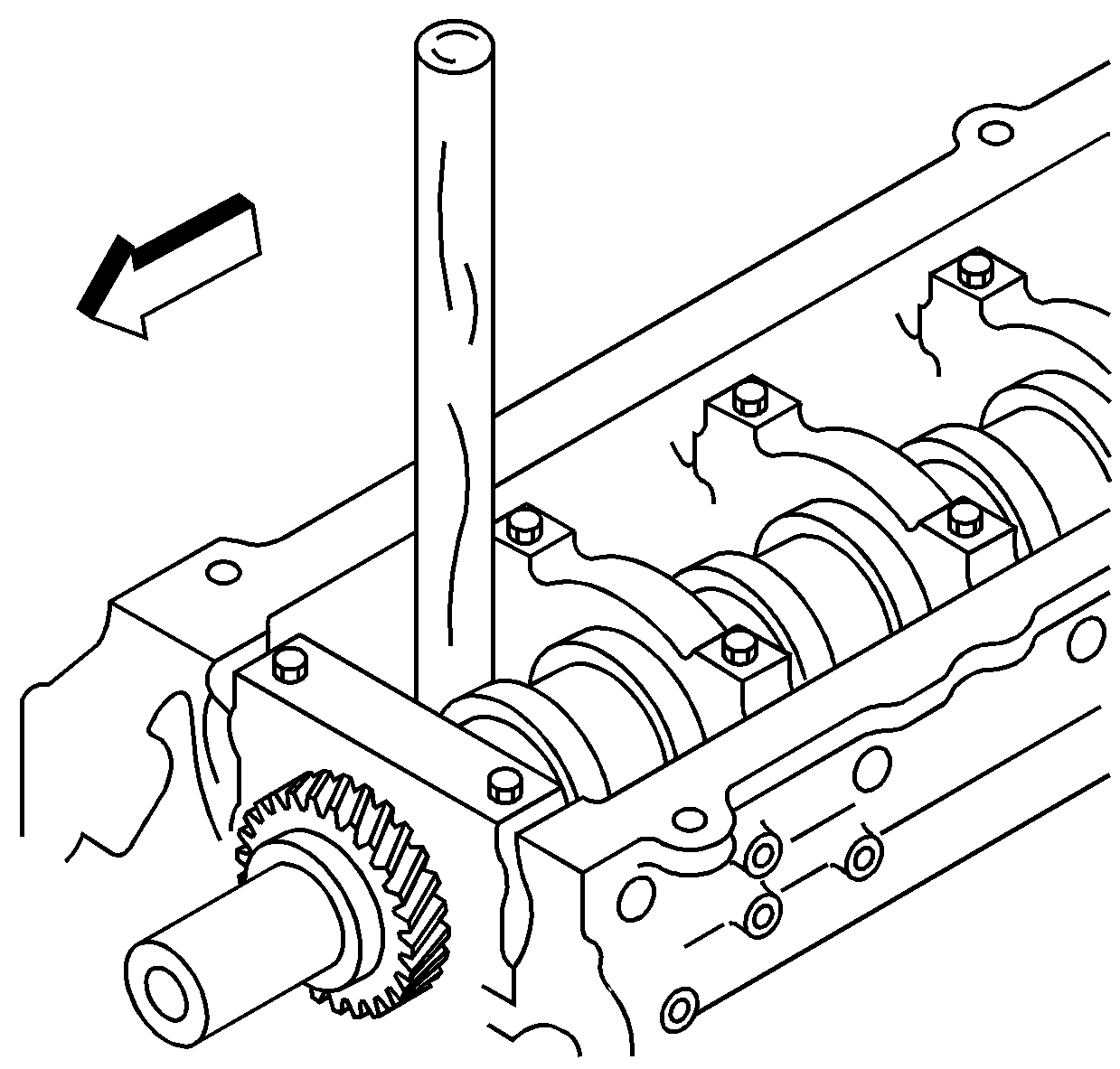
- Install the camshaft and gear assembly into the cylinder block, aligning the camshaft gear to the crankshaft gear as shown.
- Install the camshaft thrust plate bolts and tighten to 22 N·m (16 lb ft).
- Remove the exciter ring bolt that was installed to hold the spring tension of the two piece cam gear.
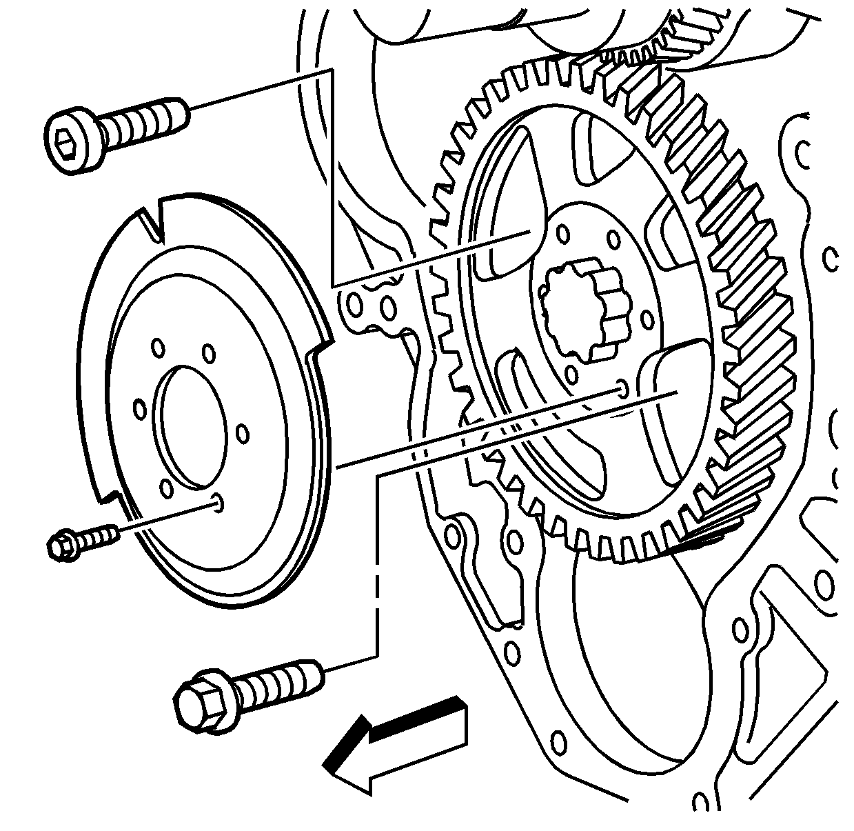
- Install the camshaft position sensor exciter ring to the camshaft gear.
- Install the camshaft position sensor exciter ring bolts and tighten to 9 N·m (80 lb in).
- Block the crankshaft from turning using a wooden handle.
- Install the new camshaft gear bolt and tighten to 234 N·m (173 lb ft).
- Measure the camshaft end play with J 7872 Dial Indicator Set .
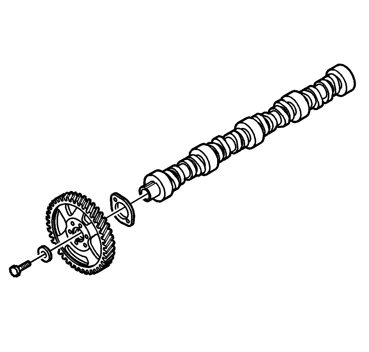
Leave the bolt finger tight.
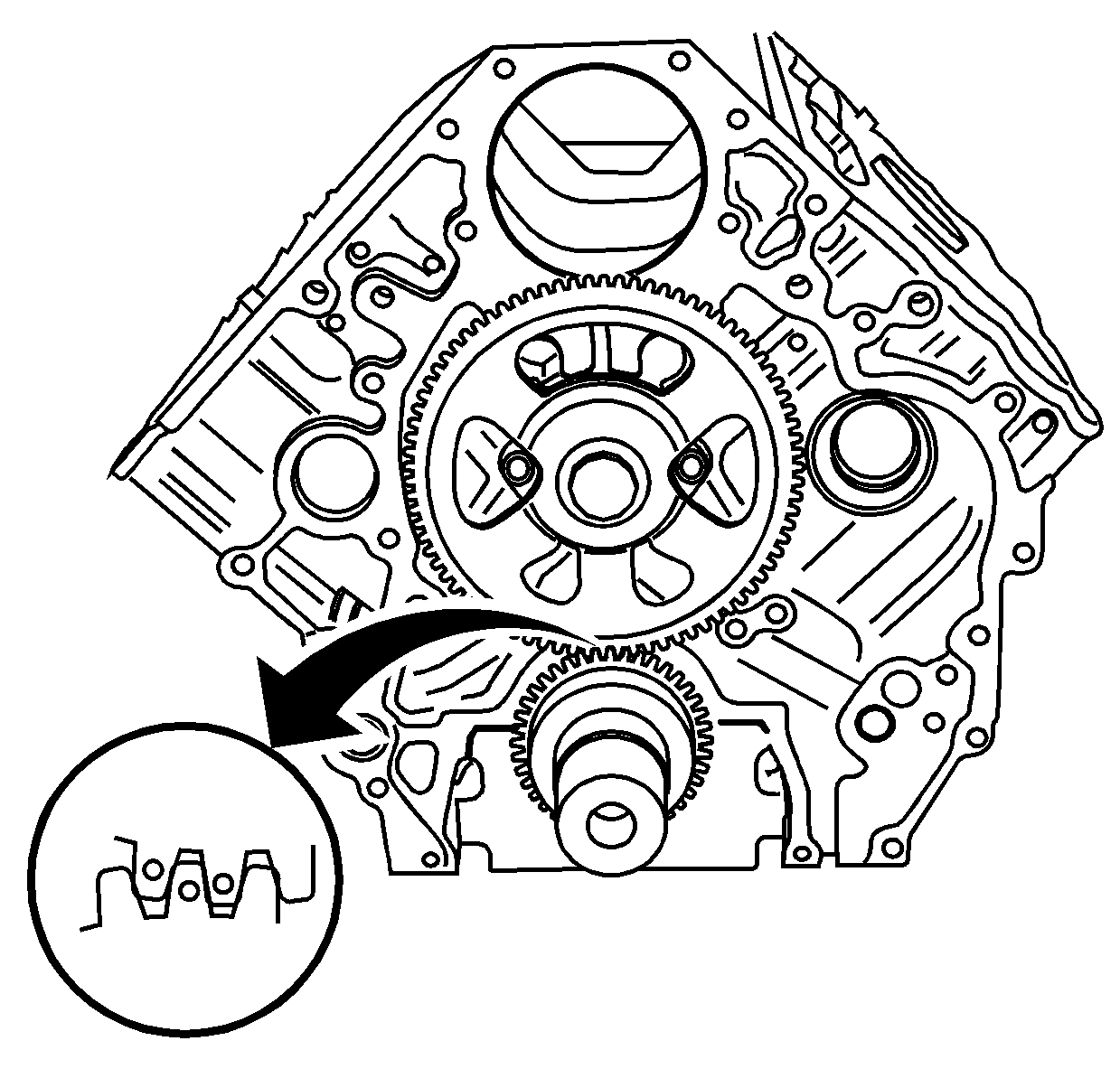
Caution: Refer to Fastener Caution in the Preface section.
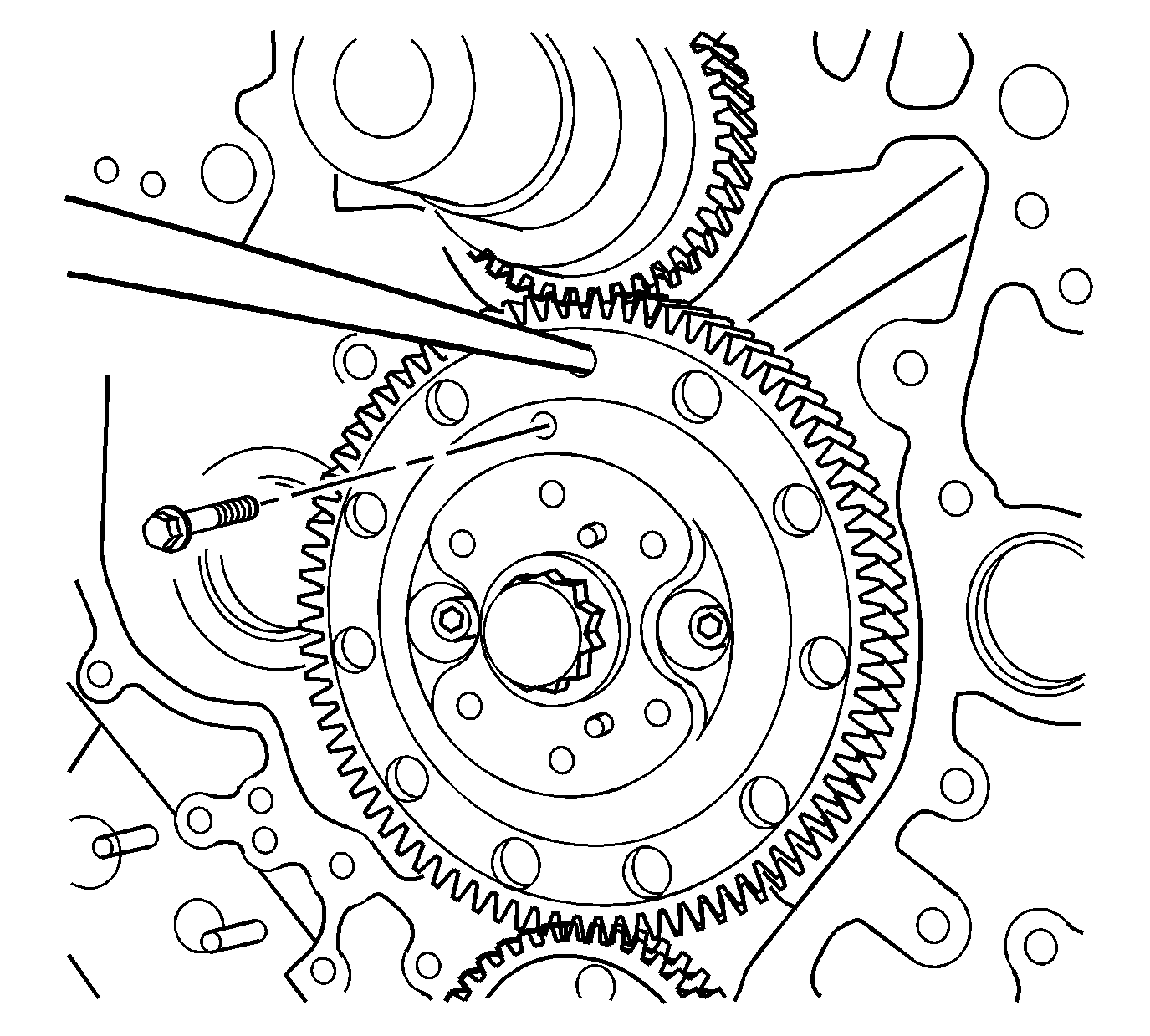
Note: Use a suitable tool to relieve the spring tension while removing the locking bolt.
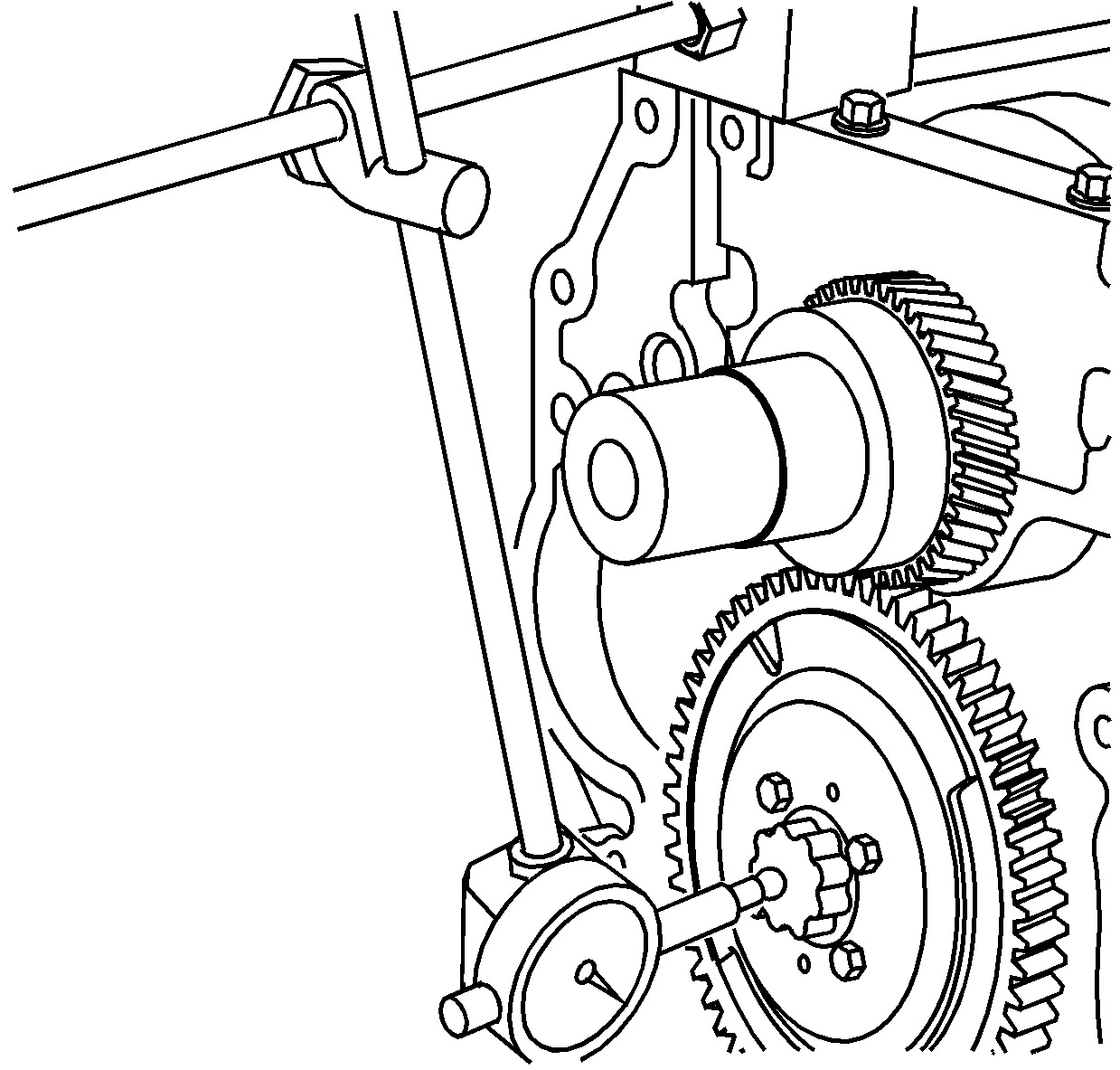
| • | The production value is 0.050-0.114 mm (0.0020-0.0045 in) and service limit is 0.2 mm (0.0079 in). |
| • | Replace the camshaft gear or the camshaft thrust plate if measured value exceeds the service limit. |
