For 1990-2009 cars only
Special Tools
J 33163 Valve Tray Set
For equivalent regional tools, refer to Special Tools.
- Position the control valve assembly on the work table so that the main valve body assembly is facing up.
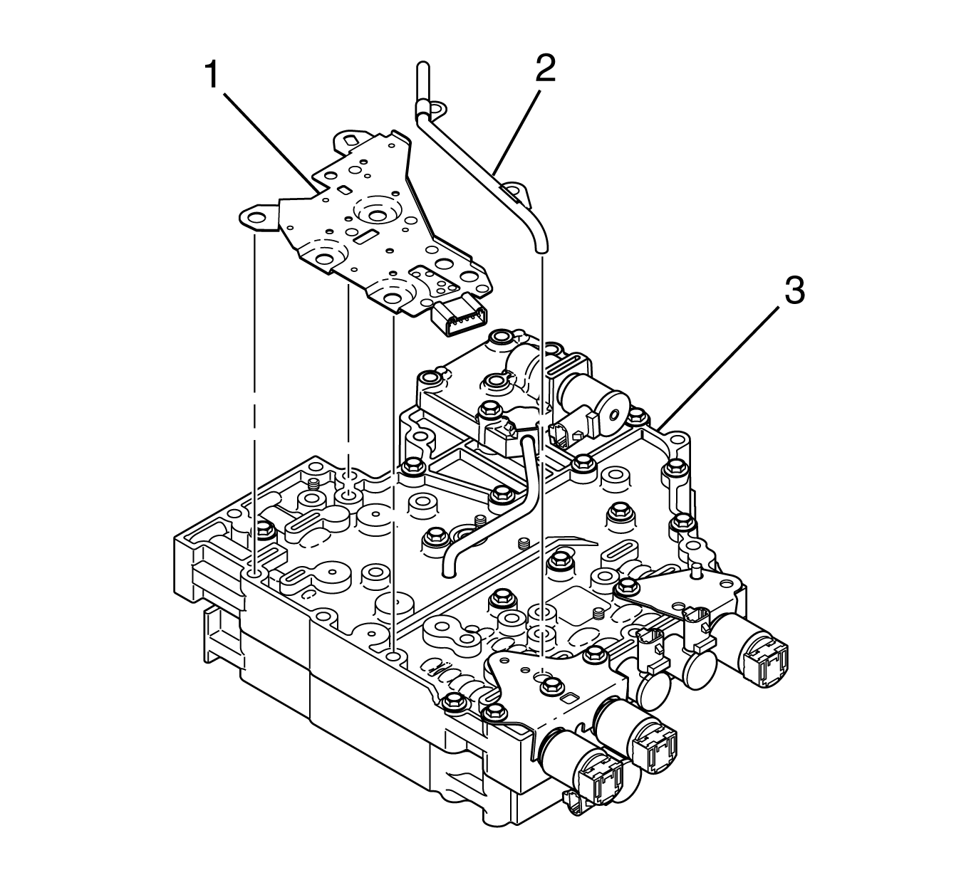
- Remove 6 bolts (1) retaining the transmission fluid pressure (TFP) switch to the main valve body.
- Remove the TFP switch (1) from the main valve body (3).
- Remove 2 bolts retaining the reverse signal pipe (2) to the main valve body (3).
- Remove the reverse signal pipe (2) from the main valve body (3).
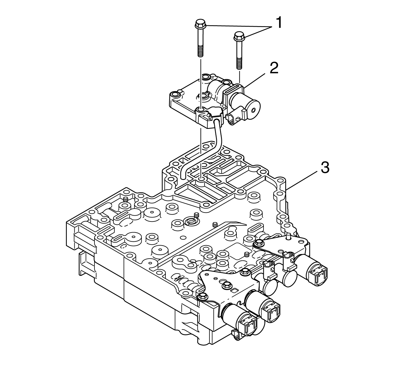
- Remove 2 bolts (1) retaining the modulated main pressure solenoid valve body to the main valve body (3).
- Remove the modulated main pressure solenoid valve body (2) and six speed tube.
- Remove the modulated main pressure (MAIN MOD) solenoid retainer (5) from the bottom of the valve body.
- Remove the MAIN MOD solenoid (3).
- Remove 2 O-rings (4) from the MAIN MOD solenoid (3).
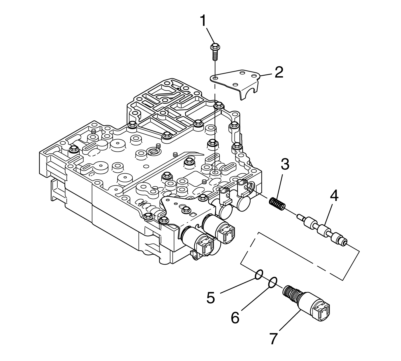
- Remove 1 bolt (1) retaining the torque converter clutch pressure control solenoid (TCC PCS) bracket to the main valve body.
- Remove the TCC PCS bracket (2).
- Remove the TCC PCS (7), valve (4), and spring (3).
- Remove the O-rings (5, 6) from the TCC PCS (7).
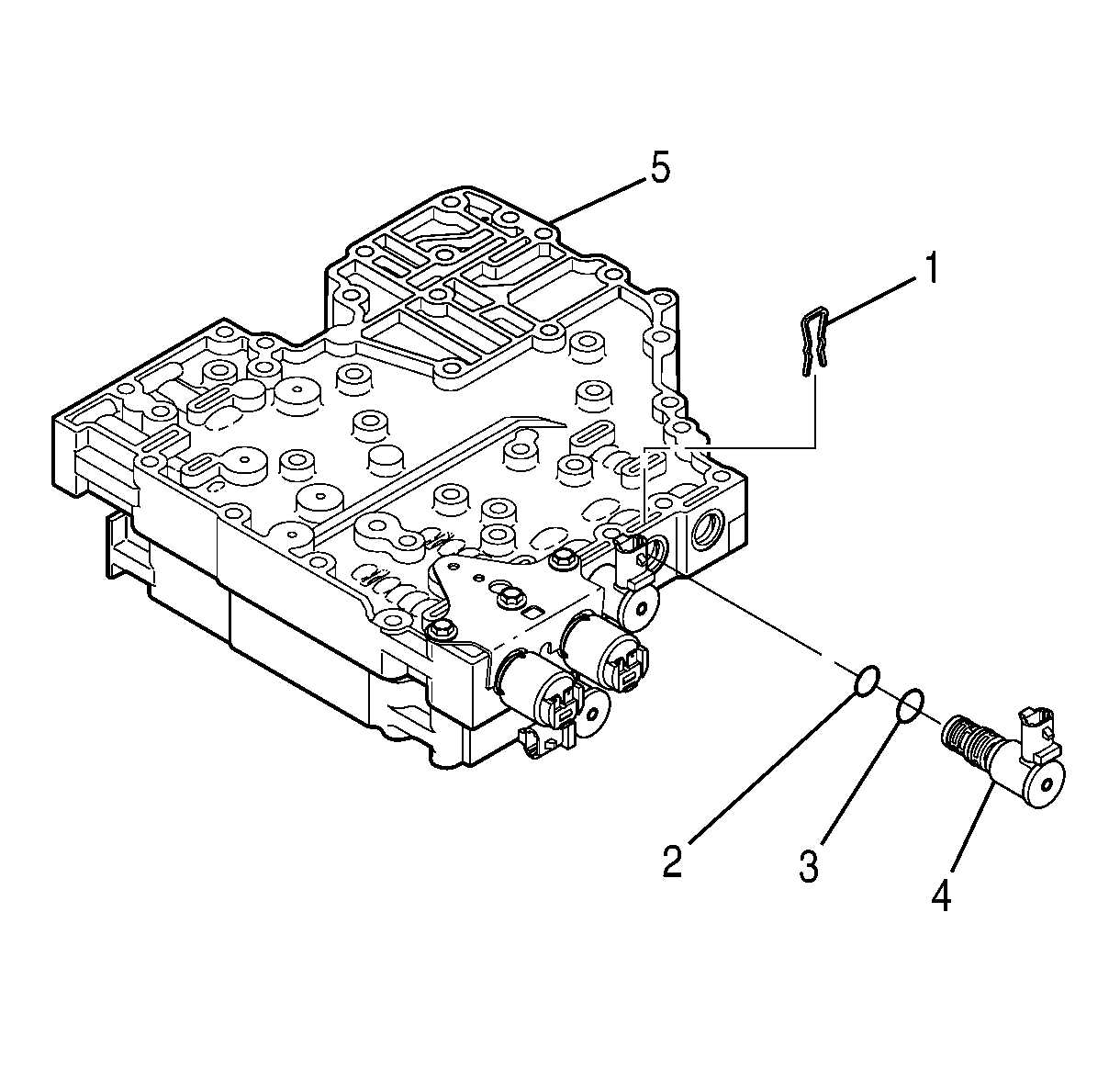
- Remove the shift solenoid 2 (SS2) retainer (1).
- Remove the SS2 (4).
- Remove the O-rings (2, 3) from the SS2 (4).
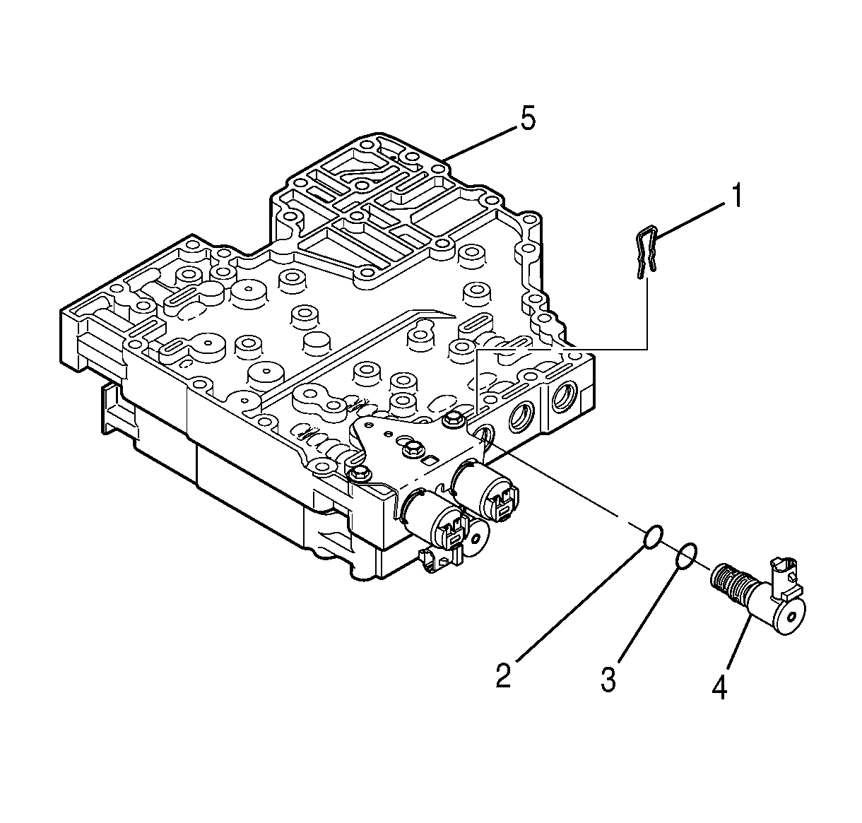
- Remove the shift solenoid 3 (SS3) retainer (1).
- Remove the SS3 (4).
- Remove the O-rings (2, 3) from SS3 (4).
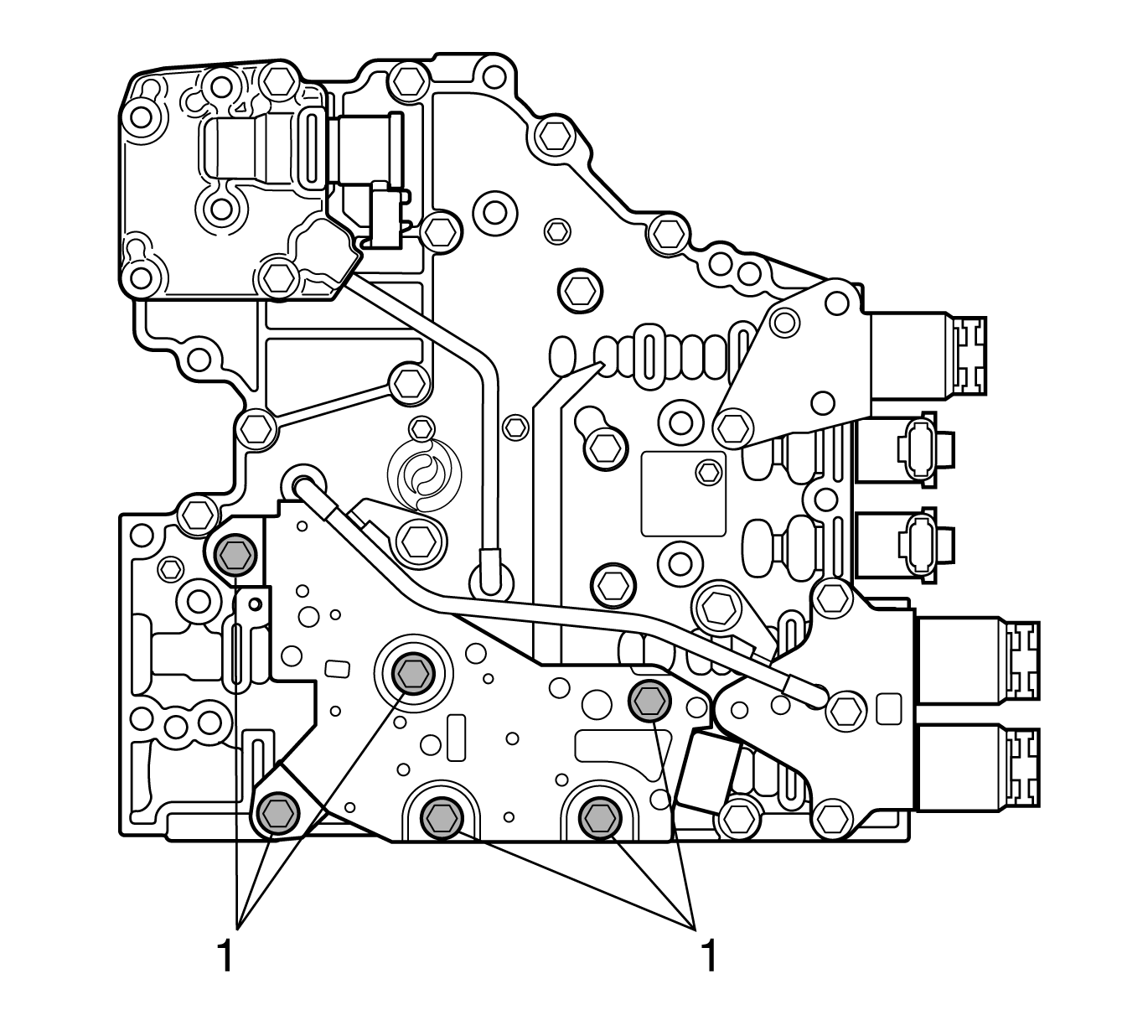
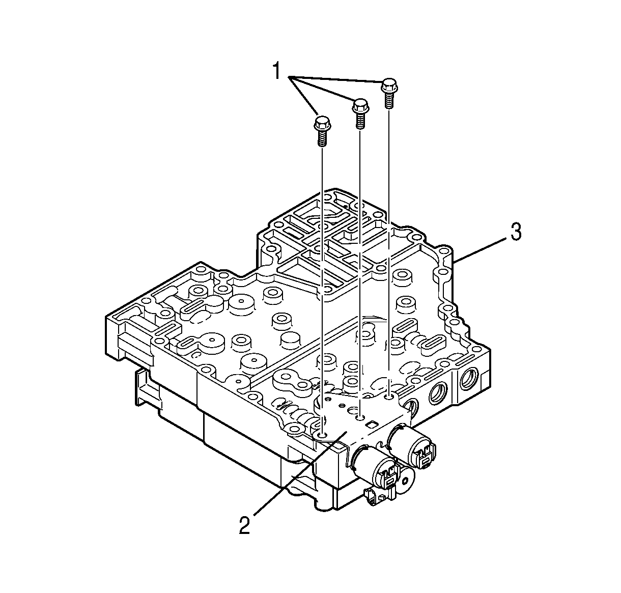
- Remove 3 bolts (1) that retain the PCS1 and PCS2 retaining bracket (2) to the main valve body (3).
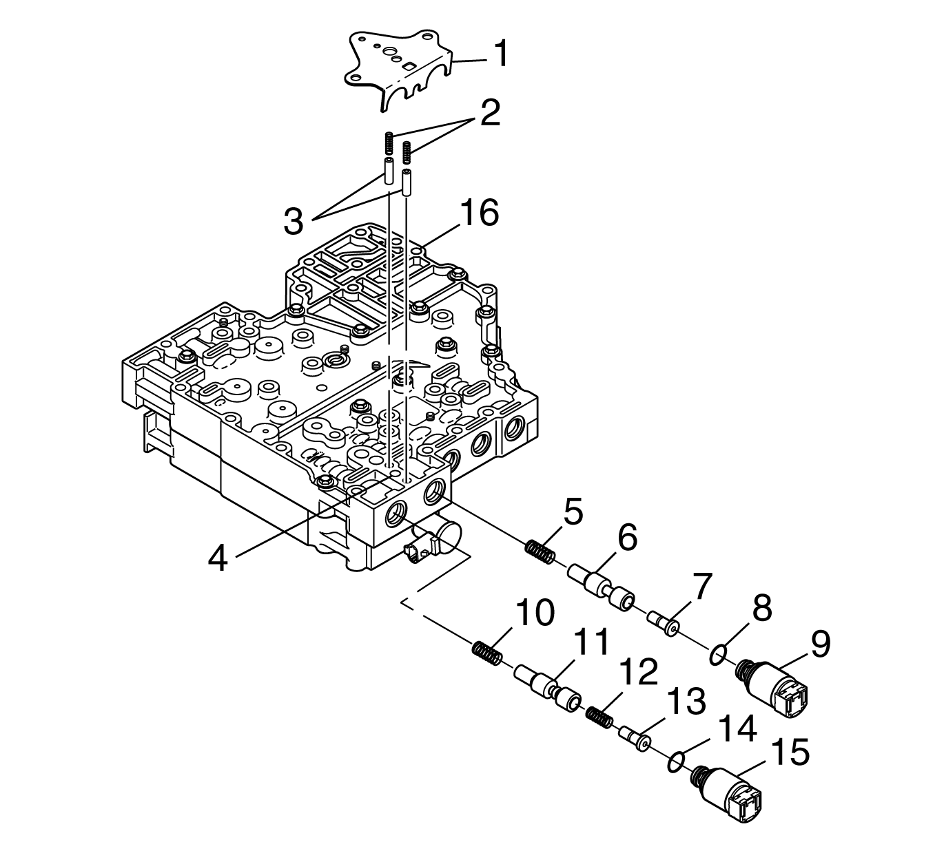
- Remove the PCS1 and PCS2 retaining bracket (1), 2 accumulator springs (2), and 2 accumulator plugs (3).
- Remove the PCS1 (15), valve (13), spring (12), valve (11), and spring (10).
- Remove the PCS2 (9), valve (7), valve (6), and spring (5).
- Remove the O-ring (14) from the PCS1 (15).
- Remove the O-ring (8) from the PCS2 (9).
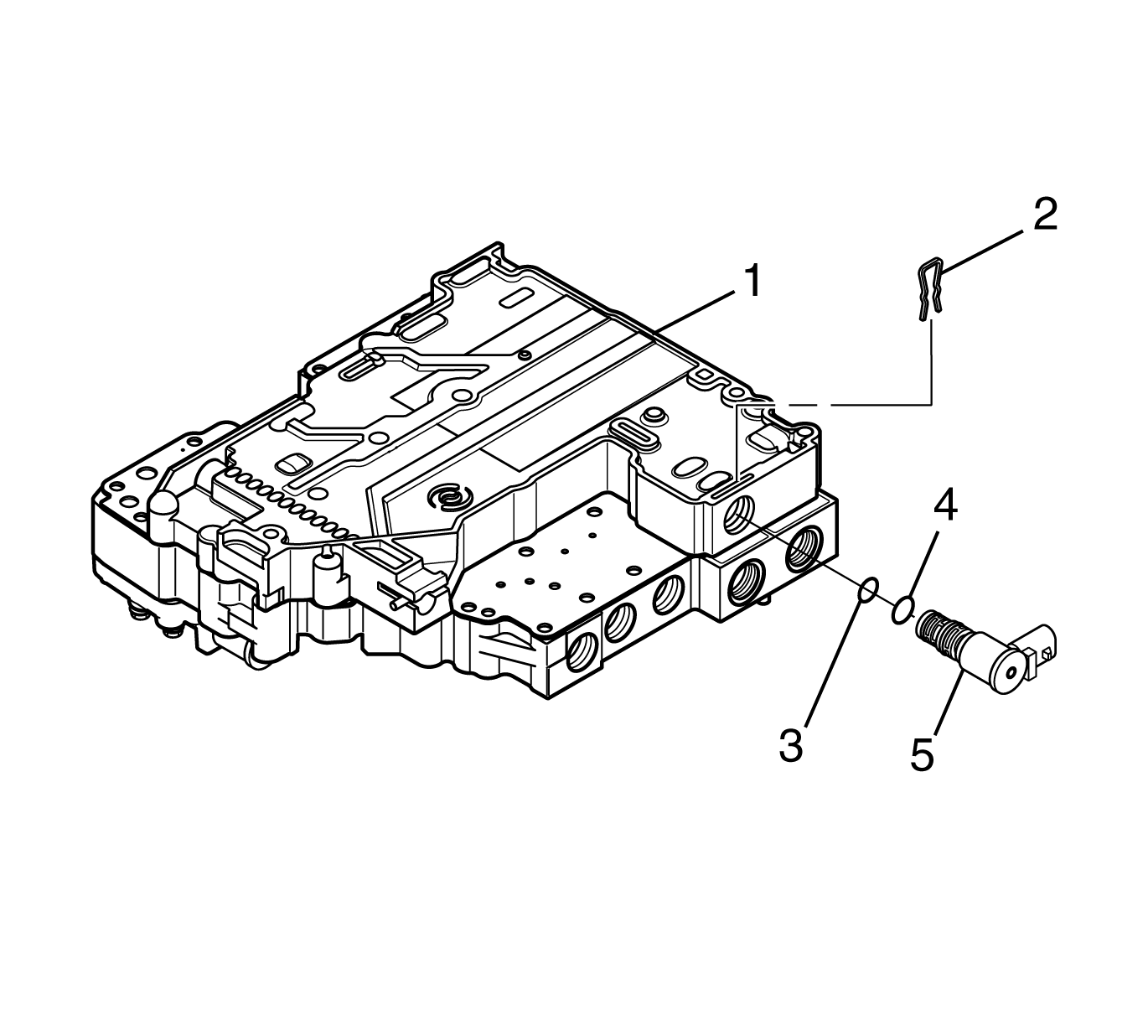
- Position the control valve body on the work table so that the shift valve body (1) is facing up.
- Remove the shift solenoid 1 (SS1) retainer (2).
- Remove the SS1 (5).
- Remove the O-rings (3, 4) from SS1 (5).
- Position the control valve assembly so that the main valve body is facing up.
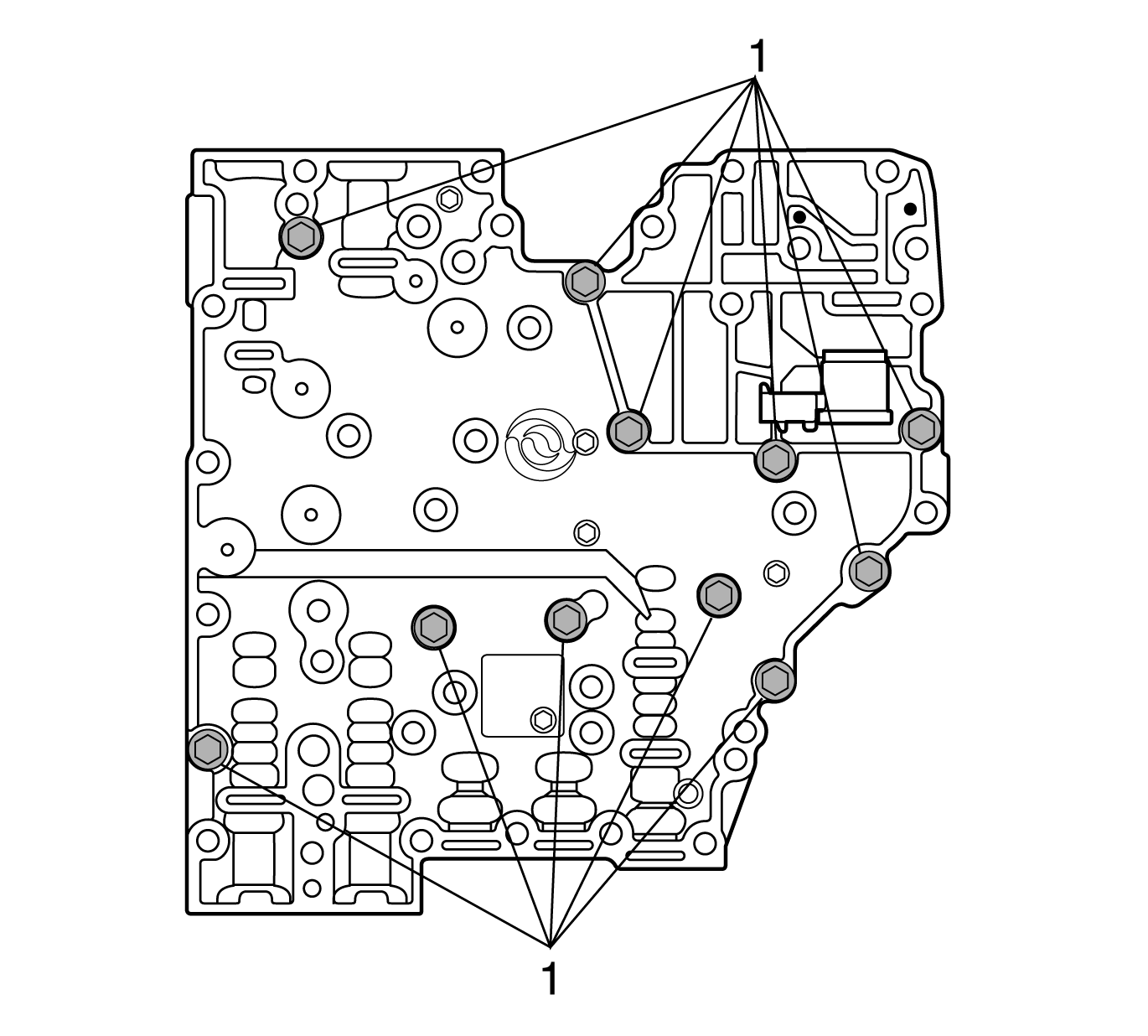
- Remove 7 of the 11 bolts marked (1) retaining the shift valve body and the main valve body together.
- Position the control valve body assembly on the work table so that the main valve body is on edge, sideways.
- Loosen the remaining 4 bolts marked (1) so that the bolts are partially threaded into the shift valve body and protrude from the main valve body.
- Gently tap the bolts until the assembly separates.
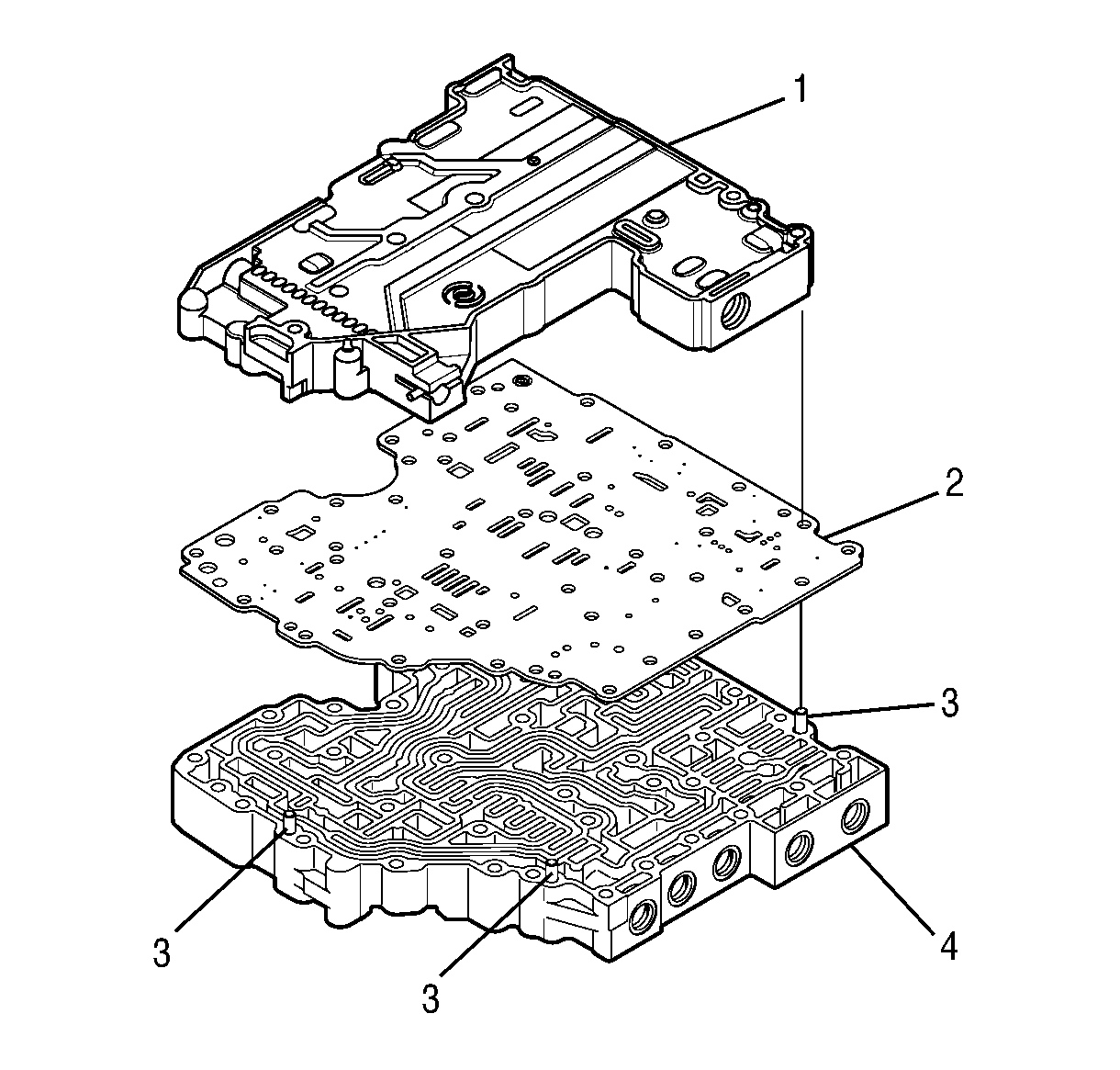
- Position the control valve assembly on the work table so that the shift valve body (1) is facing up.
- Separate the shift valve body assembly (1), the separator plate (2), and the main valve body assembly (4).
Note: To help prevent confusing parts on assembly, use J 33163 tray to store the removed control valve assembly valves, springs, and stops.
Caution: DO NOT damage the solenoids when turning over the control valve assembly.
