For 1990-2009 cars only
Special Tools
J 44587 Main Shaft Holder
For equivalent regional tools, refer to Special Tools.
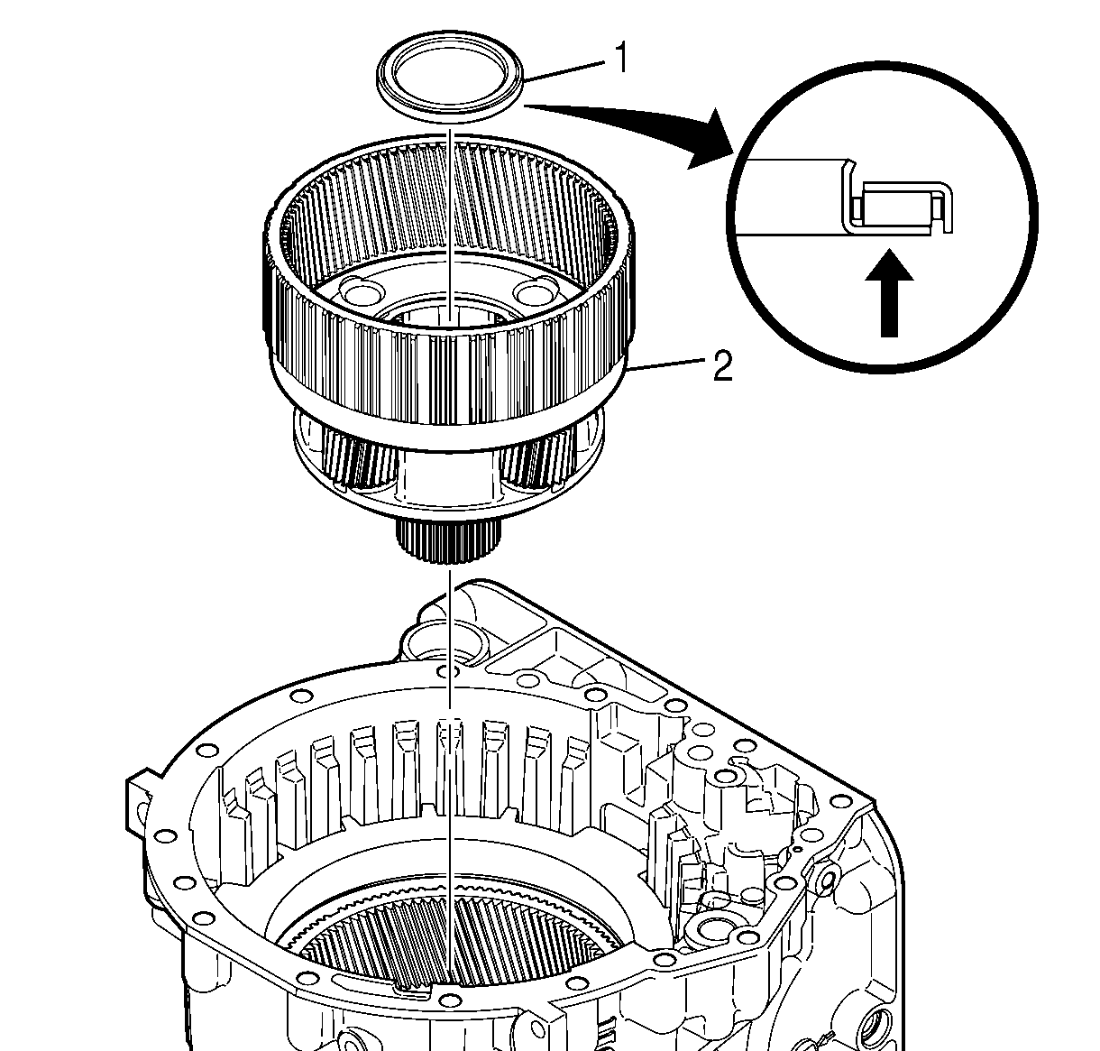
- Install the intermediate carrier module (2).
- Rotate the intermediate carrier module (2) until the module drops into place.
- Align thrust bearing assembly (1) so that the blue stripe on the thrust bearing assembly is facing towards the intermediate carrier module (2).
- Install the thrust bearing assembly (1) onto the intermediate carrier module (2).
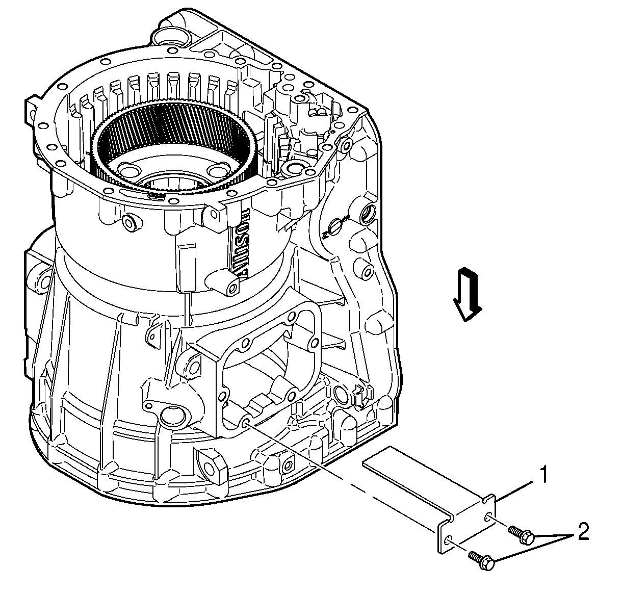
- Align J 44587 holder J 44587 holder (1) with the power takeoff (PTO) access as follows:
- Install J 44587 holder (1) into the PTO access.
- Install 2 bolts (2) into J 44587 holder (1) and tighten the bolts snugly.
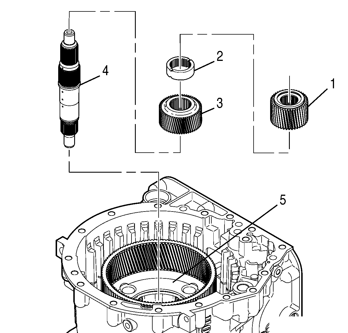
- Install the intermediate sun gear (3) and the sun gear spacer (2) onto the main shaft (4).
- As a unit, install the main shaft (4), the intermediate sun gear (3), and the sun gear spacer (2) into the intermediate planetary carrier module (5).
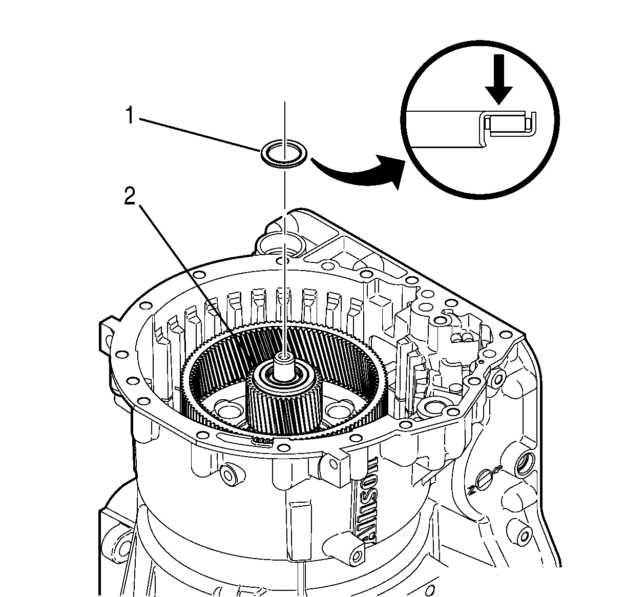
- Align the output sun gear (1) so that the flat side of the sun gear is facing the sun gear spacer.
- Install the output sun gear (1) onto the main shaft (4).
- Make sure the output sun gear and sun gear spacer splines are engaged.
- Align the thrust bearing assembly (1) so that the blue stripe on the thrust bearing assembly is facing away from the output sun gear (2).
- Install the thrust bearing assembly (1) into the output sun gear (2).

Caution: Installing the thrust bearing incorrectly may cause permanent damage to the transmission.

Caution: Do not rotate the transmission from the nose-up position without installing J 44587. Failure to install J 44587 and rotating the transmission will cause clearance issues during assembly and possible damage to the transmission.
| • | The tongue of J 44587 holder is facing toward the PTO access. |
| • | The bolts holes of J 44587 holder are aligned with the 2 front bolt holes of the PTO access. |


Caution: Installing the thrust bearing incorrectly may cause permanent damage to the transmission.
