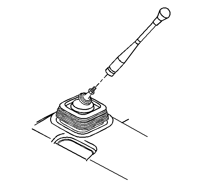
Removal Procedure
- Remove the control lever boot from the control lever.
Note: DO NOT move the shift lever assembly adjustment nut if replacing the control lever.
- Remove the control lever.
Installation Procedure
- Install the control lever.
- If alignment of the control lever is necessary, or if the shift lever assembly was replaced perform the following:
| 2.1. | The nut must be seated at the bottom of the thread runout on the shift lever. |
| 2.2. | Seat the control lever against the shift lever assembly adjustment nut. |
| 2.3. | Back the control lever off the nut in order to align the index mark on the control lever perpendicular to the edge of the control lever boot retainer. |
| 2.4. | Ensure that the index mark is located on the passenger side and that the shift pattern is aligned parallel to the vehicle centerline or rotated no more than 6 degrees clockwise. |
Caution: Refer to Fastener Caution in the Preface section.
| 2.5. | Hold the control lever and tighten the shift lever assembly nut against the control lever. |
Tighten
Tighten the nut to 37 N·m (27 lb in).
| 2.6. | Install the control lever boot to the control lever. |
