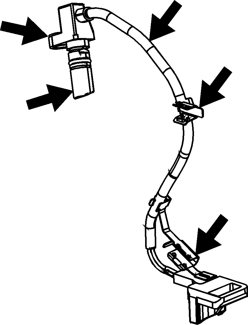
- Inspect the input speed sensor (ISS) assembly (250) for the following conditions:
| • | Cracked or damaged housing |
| • | Worn, broken or missing harness brackets; replace the ISS assembly if necessary |
| • | Damaged or worn wining or electrical connector |
| • | Loose, missing or damaged mounting bolt insert |

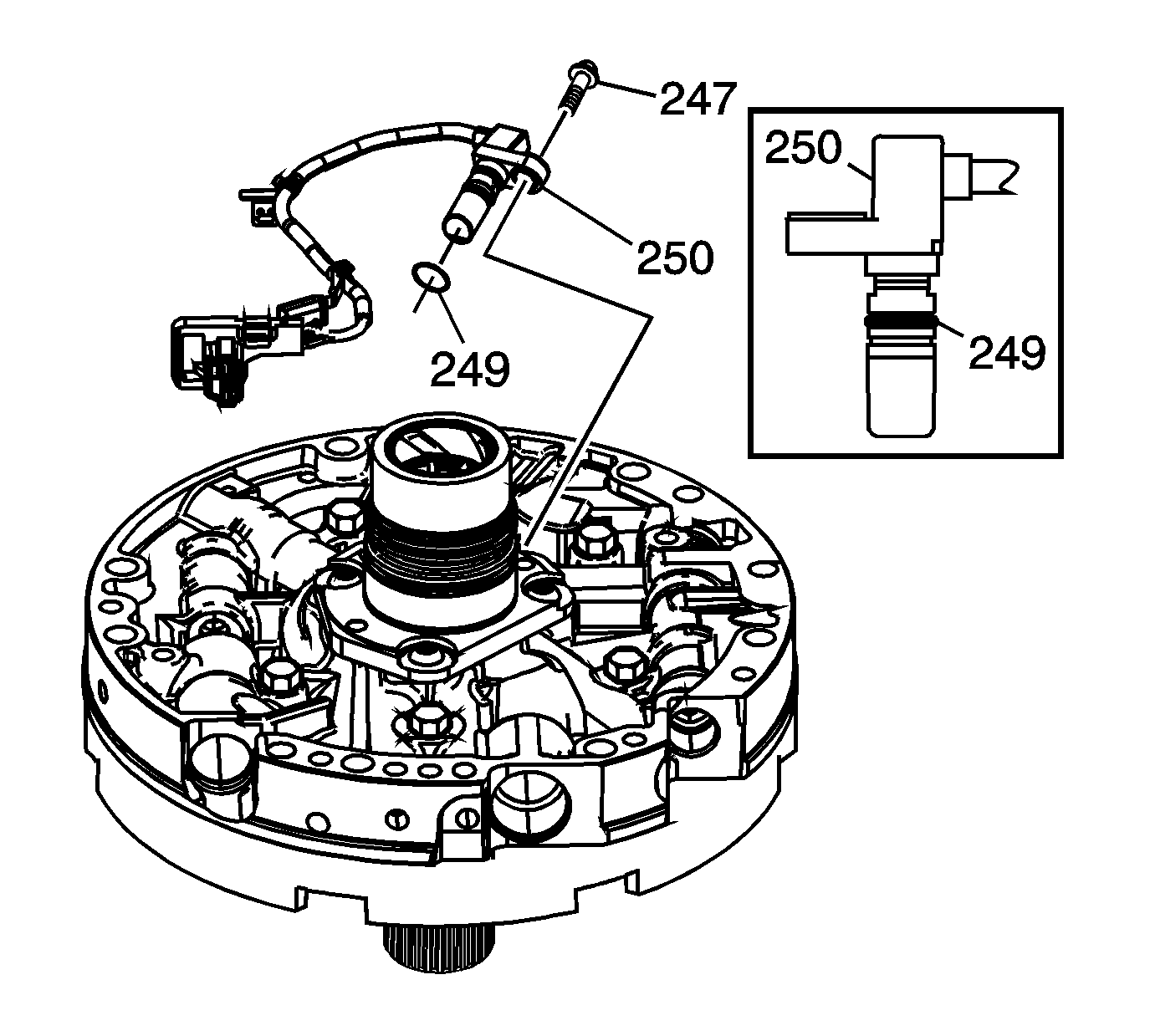
- Remove the ISS O-ring (249) and discard.
- Lubricate NEW O-ring (249) with transmission fluid and position the O-ring as shown.
- Insert the ISS (250) into oil pump ISS bore and fully seat.
- Align ISS bolt hole insert with the oil pump mounting hole.
Notice: Use the correct fastener in the correct location. Replacement fasteners
must be the correct part number for that application. Fasteners requiring
replacement or fasteners requiring the use of thread locking compound or sealant
are identified in the service procedure. Do not use paints, lubricants, or
corrosion inhibitors on fasteners or fastener joint surfaces unless specified.
These coatings affect fastener torque and joint clamping force and may damage
the fastener. Use the correct tightening sequence and specifications when
installing fasteners in order to avoid damage to parts and systems.
- Install bolt (247).
Tighten
Tighten the bolt to 9-11 N·m (6.6-8.1 lb ft).

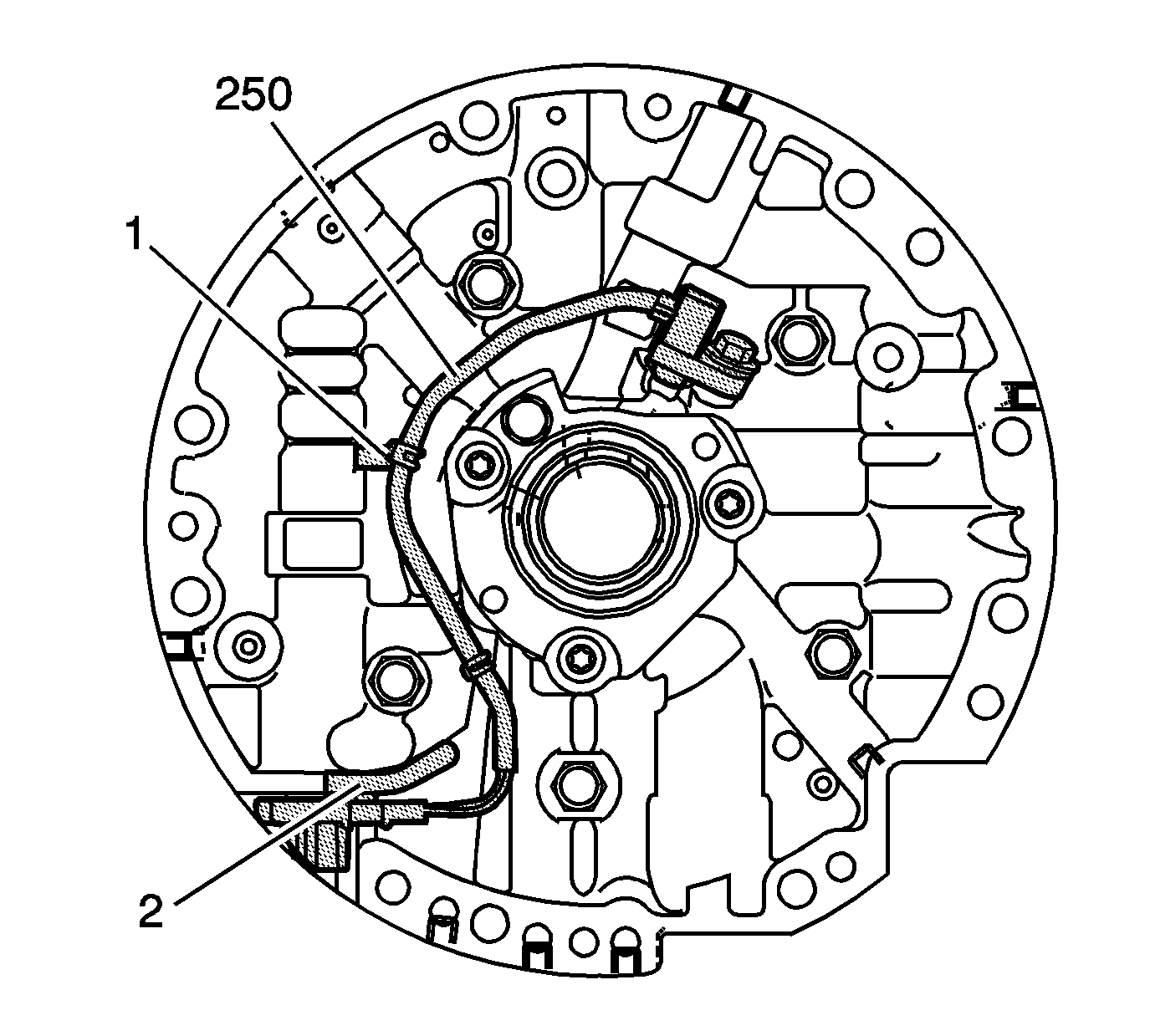
Important: Ensure the ISS brackets securley fasten the wiring harness to the pump housing.
- Route the ISS assembly (250) wire harness as shown. Install harness bracket #1 and #2 in the locations shown. Ensure the wire harness lays flat against the pump housing.


