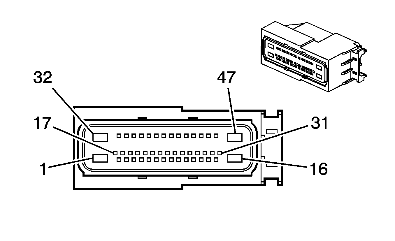
| Connector 1: | Power Take Off (PTO) Module |
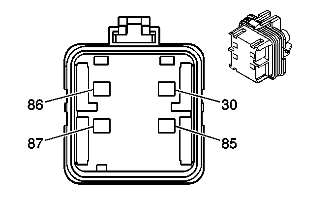
| Connector 2: | Power Take Off (PTO) Relay |
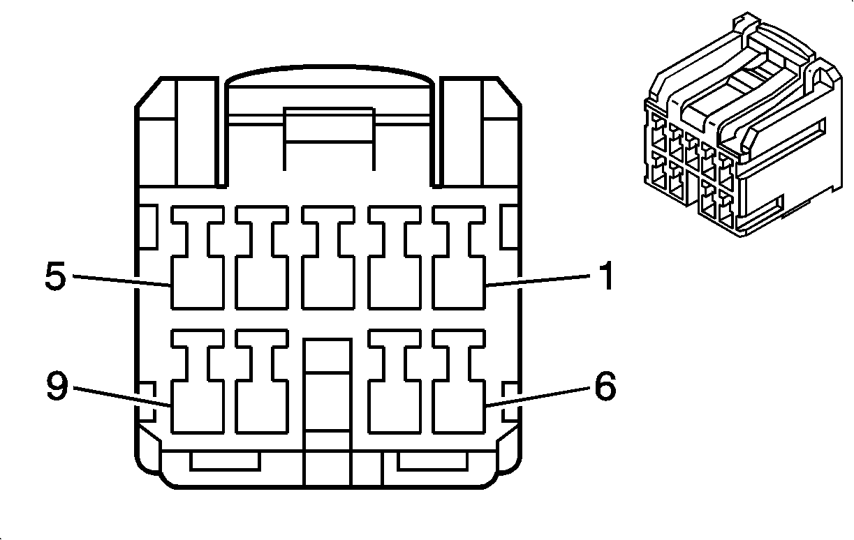
| Connector 3: | Power Take Off (PTO) Switch |
Power Take Off (PTO) Module

Connector Part Information
|
Terminal Part Information
|
Pin | Wire Color | Circuit No. | Function |
|---|---|---|---|
1 | 2 BK/WH | 451 | Ground |
2 | 0.35 YE | 970 | 5-Volt Reference |
3-5 | -- | -- | Not Used |
6 | 0.5 TN | 2501 | High Speed GMLAN Serial Data Bus- |
7 | 0.5 TN/BK | 2500 | High Speed GMLAN Serial Data Bus+ |
8 | 0.35 PU | 974 | Low Reference |
9 | -- | -- | Not Used |
10 | 0.35 L-BU | 977 | Remote Mode PPS |
11 | 0.35 D-GN/WH | 972 | Mode Select B |
12 | 0.35 TN | 973 | Mode Select C |
13 | 0.8 BN/WH | 6085 | PTO Remote Engine Start Switch Signal |
14 | 0.35 TN | 981 | Torque Limit request Signal |
15 | 0.8 D-BU | 979 | Remote Start Arming Signal |
16 | -- | -- | Not Used |
17 | 0.35 L-BU | 5986 | Serial Data Communication Enable |
18-20 | -- | -- | Not Used |
21 | 0.5 TN | 2501 | High Seed GMLAN Serial Data Bus- |
22 | 0.5 TN/BK | 2500 | High Seed GMLAN Serial Data Bus+ |
23 | 0.35 GY/BK | 976 | Low Reference |
24-25 | -- | -- | Not Used |
26 | 0.35 BN | 971 | Mode Select A |
27 | 0.35 D-BU/WH | 6089 | PTO Remote Switch Set Signal |
28 | 0.35 PU | 2562 | PTO Relay Coil Control |
29 | 0.35 GY/BK | 6086 | PTO Switch Indicator Control |
30 | -- | -- | Not Used |
31 | 0.8 L-BU | 494 | Engine Shut Off Signal |
32 | 2 RD/WH | 4540 | Battery Positive Voltage |
33 | 0.5 D-GN/WH | 6142 | PTO Engine Shutdown Signal |
34 | 0.35 WH | 975 | 5-Volt Reference |
35-36 | -- | -- | Not Used |
37 | 0.5 L-BU/WH | 6311 | TCC Brake Signal |
38-44 | -- | -- | Not Used |
45 | 0.8 GY | 978 | Remote Mode Enable Signal |
46 | 0.8 YE | 2522 | PTO Engage Signal |
47 | 2 BN | 6381 | Power Take Off Relay Engage Signal |
Power Take Off (PTO) Relay

Connector Part Information
|
Terminal Part Information
|
Pin | Wire Color | Circuit No. | Function |
|---|---|---|---|
30 | 0.8 RD/WH | 2640 | Battery Positive Voltage |
85 | 0.35 PU | 2562 | PTO Relay Coil Control |
86 | 2 BN | 6381 | PTO Relay Engage Signal |
87 | 0.8 WH | 2561 | PTO Supply Voltage |
Power Take Off (PTO) Switch

Connector Part Information
|
Terminal Part Information
|
Pin | Wire Color | Circuit No. | Function |
|---|---|---|---|
1 | 0.35 YE | 970 | 5-Volt Reference |
2 | 0.35 BN | 971 | Mode Select A |
3 | -- | -- | Not Used |
4 | 0.35 TN | 973 | Mode Select C |
5 | 0.35 PU | 974 | Low Reference |
6 | 0.35 YE | 6817 | LED Dimming Signal |
7 | 0.35 PU/WH | 6816 | LED Dimming Signal |
8 | 0.35 GY/BK | 6086 | PTO Switch Indicator Control |
9 | 0.35 D-GN/WH | 972 | Mode Select B |
