Tools Required
J 45059 Angle Meter
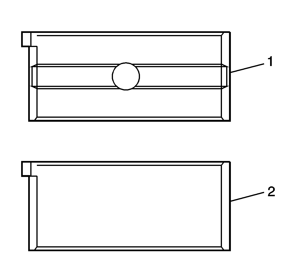
- Install the upper crankshaft bearings into the cylinder block. The bearing halves to be inserted into the crankshaft main bearing saddle have a wide groove and oil hole in the center of the bearing (1).
- Install the lower crankshaft bearings into the crankshaft bearing caps. The bearing halves to be inserted into the crankshaft main bearing caps do NOT have an oil hole or groove in the bearing (2).
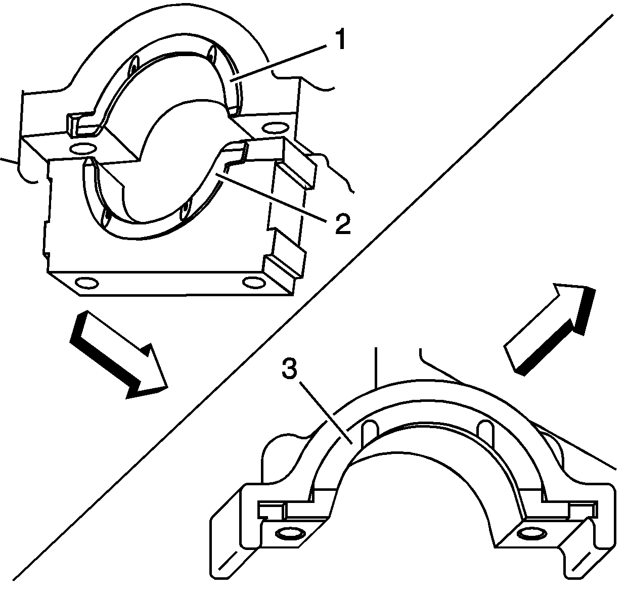
- Install the upper thrust bearings to the cylinder block. There are two thrust bearings (1 and 3) in the cylinder block and one lower thrust bearing in the No. 5 crankshaft bearing cap (2).
- Lubricate the crankshaft bearing surfaces with engine oil.
- Install the crankshaft into the cylinder block.
- Install the No. 5 crankshaft bearing cap with the lower thrust bearing (2).
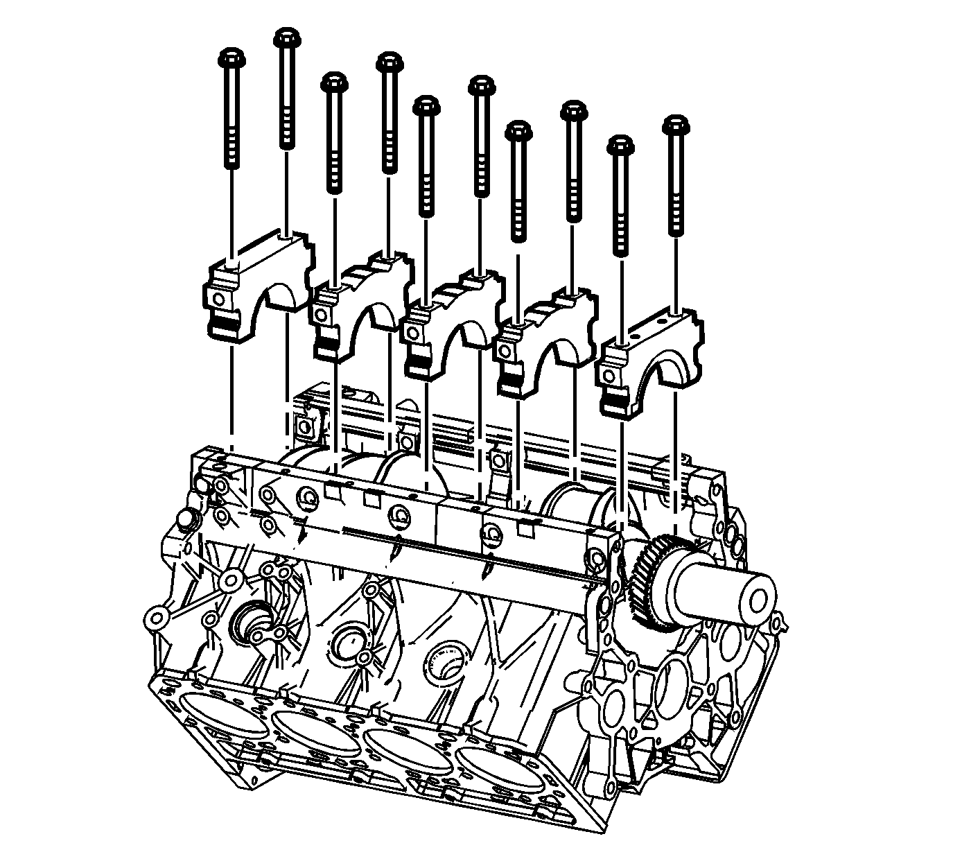
- Install the remaining four crankshaft bearing caps.
- Install the NEW crankshaft bearing cap bolts.
- Tighten the crankshaft bearing cap bolts in the proper sequence.
- Clean the crankshaft bearing side cap bolt threads, sealing flange and mounting holes with GM P/N 12377981 (Canadian P/N 10953463) or equivalent. Dry the bolts and mounting holes with compressed air.
- Apply GM P/N 12346004 (Canadian P/N 10953480) to the threads and sealing flange of the bolts.
- Install the ten bolts.
- Install the oil pressure sensor.
Notice: This component uses bolts with a preapplied molybdenum disulfide coating for thread lubrication. Do not remove the coating or use any additional lubricant. Improperly lubricated threads will adversely affect the bolt torque and clamp load. Improper bolt torque and clamp load can lead to engine damage.
Notice: Use the correct fastener in the correct location. Replacement fasteners must be the correct part number for that application. Fasteners requiring replacement or fasteners requiring the use of thread locking compound or sealant are identified in the service procedure. Do not use paints, lubricants, or corrosion inhibitors on fasteners or fastener joint surfaces unless specified. These coatings affect fastener torque and joint clamping force and may damage the fastener. Use the correct tightening sequence and specifications when installing fasteners in order to avoid damage to parts and systems.
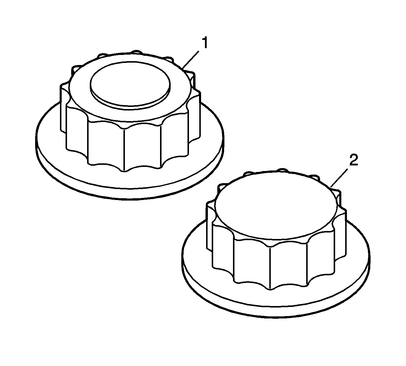
Important: There are two different length crankshaft bearing cap bolts in production depending on the counter bore of the threaded hole/block. Using the wrong bolt may lead to improper thread engagement, bottoming out or improper clamp load. Look at the bolt head surface to determime which bolt was used in production. The bolt head will have either a raised circle (1) or it will be unmarked (2). Replace the bolt with the same type.
Tighten
| • | 1st step 98 N·m (72 lb ft). |
| • | 2nd step 132 N·m (97 lb ft). |
| • | 3rd step 30 degrees using J 45059 . |
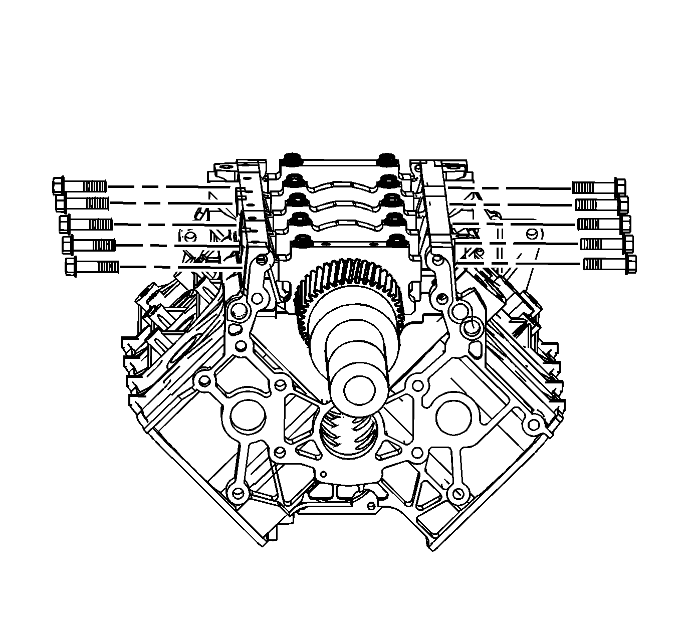
Tighten
Tighten the crankshaft bearing cap side bolts to 70 N·m (52 lb ft).
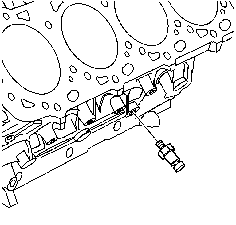
Tighten
Tighten the oil pressure sensor to 41 N·m (30 lb ft).
