For 1990-2009 cars only
Removal Procedure
- Remove the intake manifold. Refer to Intake Manifold Replacement .
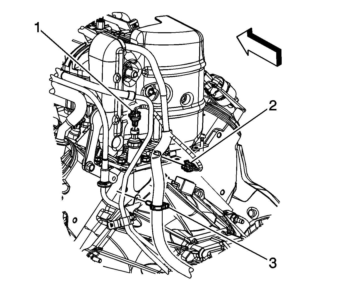
- Disconnect the engine harness electrical connector (1) from the oil pressure sensor.
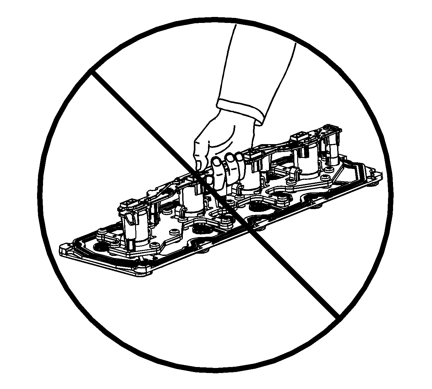
- DO NOT lift the valve lifter oil manifold by the electrical lead frame.
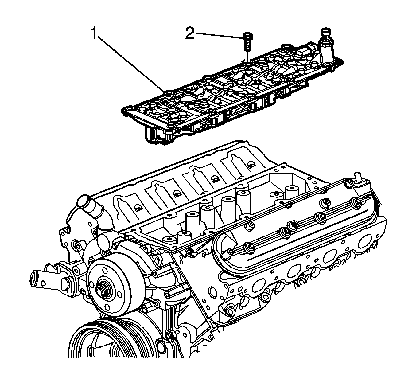
- Remove the valve lifter oil manifold bolts (2).
- Remove the valve lifter oil manifold (1).
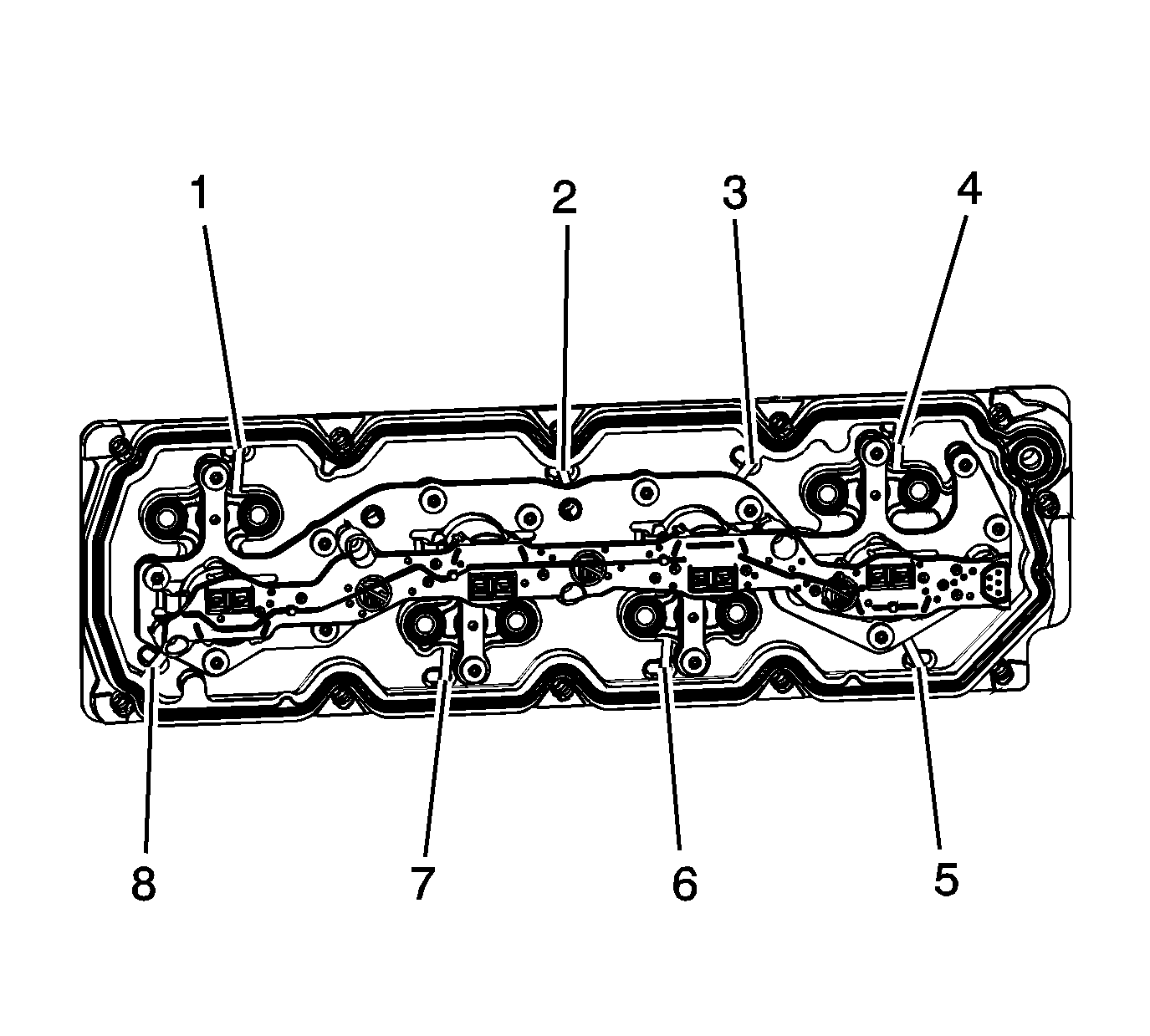
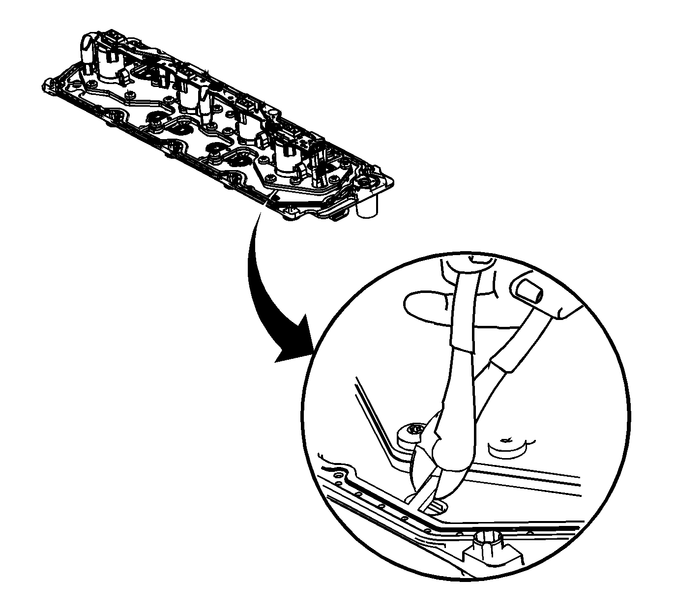
- Identify the 8 gasket retaining strap locations (1-8).
- Using a cutter type tool, cut the 8 retaining straps.
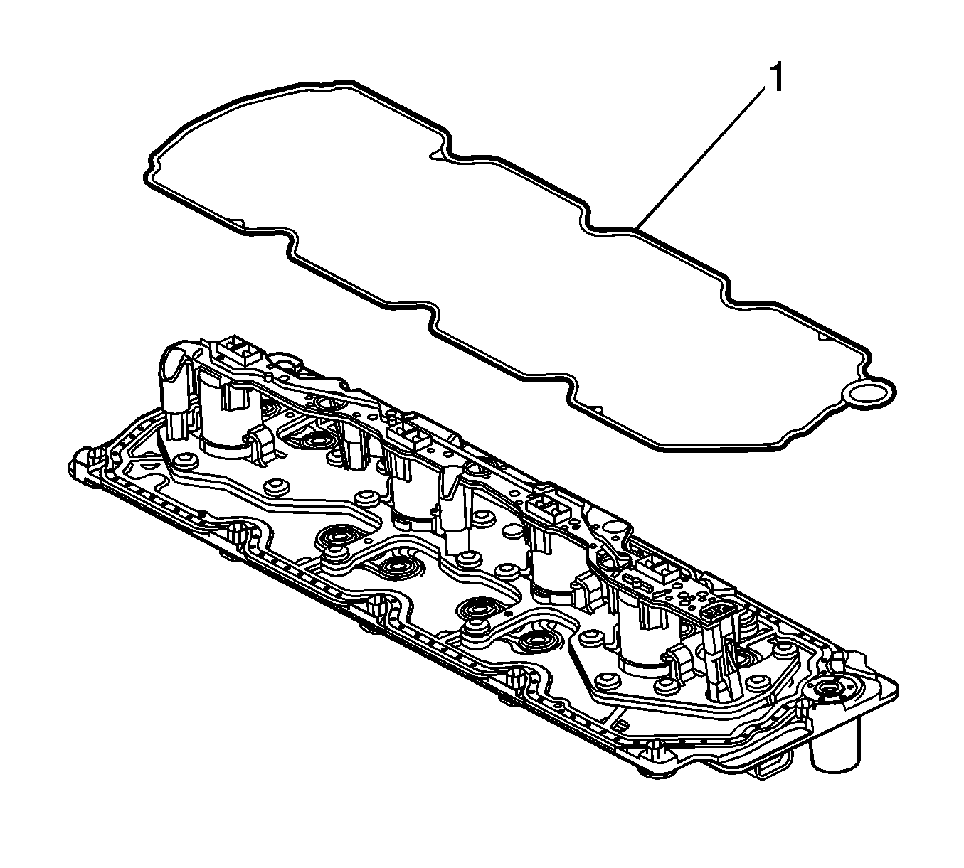
- Remove the outer gasket (1) from the valve lifter oil manifold.
Important: Remove only the outer gasket from the manifold. Do not disassemble any of the internal components of the manifold in an attempt to remove the 8 inner sealing gaskets. If the inner gaskets are cut or damaged, replace the manifold as an assembly. Only use a wire-cutter type tool in order to minimize the amount of debris. Do not use a rotary-type cutting tool on the retaining straps.
Installation Procedure
Important: All gasket surfaces should be free of oil or other foreign material during assembly.
- Place the service gasket (1) onto the valve lifter oil manifold.
- Install the valve lifter oil manifold (1) to the engine.
- Install the valve lifter oil manifold bolts (2).
- Connect the engine harness electrical connector (1) to the oil pressure sensor.
- Install the intake manifold. Refer to Intake Manifold Replacement .


Notice: Refer to Fastener Notice in the Preface section.
Tighten
Tighten the bolts to 25 N·m (18 lb ft).

