For 1990-2009 cars only
Tools Required
J 24319-B Steering Linkage and Tie Rod Puller
Removal Procedure
- Remove the engine shield, if equipped. Refer to Engine Shield Replacement .
- Remove the steering linkage shock absorber from the relay rod, if equipped. Refer to Steering Linkage Shock Absorber Replacement .
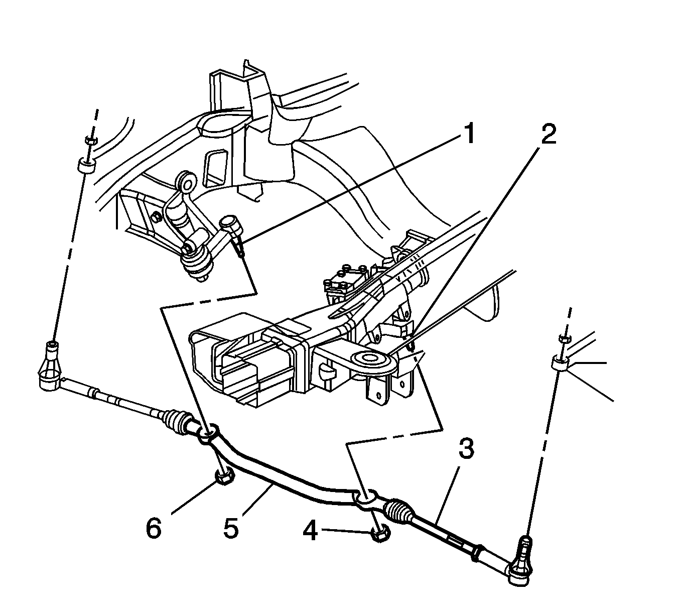
- Remove the steering linkage inner tie rods (3). Refer to Steering Linkage Inner Tie Rod Replacement .
- Remove the idler arm nut (6) and separate the idler arm (1) from the relay rod (5) using puller J 24319-B .
- Remove the pitman arm nut (4) and separate the pitman arm (2) from the relay rod (5) using puller J 24319-B .
- Remove the relay rod (5) from the vehicle.
- Inspect the threads and seals on all steering related components. Repair or replace components as needed.

Important: Discard the idler arm nut (6) and the pitman arm nut (4).
Installation Procedure
- Install the relay rod (5) to the vehicle.
- Install the pitman arm (2) to the relay rod (5).
- Install the idler arm (1) to the relay rod (5).
- Install the pitman arm nut (4).
- Install the idler arm nut (6).
- Install the steering linkage inner tie rods (3). Refer to Steering Linkage Inner Tie Rod Replacement .
- Install the steering linkage shock absorber to the relay rod, if equipped. Refer to Steering Linkage Shock Absorber Replacement .
- Install the engine shield, if equipped. Refer to Engine Shield Replacement .
- Adjust the front toe. Refer to Front Toe Adjustment .

Notice: Refer to Fastener Notice in the Preface section.
Important: Use a new pitman arm nut.
Tighten
Tighten the nut to 62 N·m (46 lb ft).
Important: Use a new idler arm nut.
Tighten
Tighten the nut to 62 N·m (46 lb ft).
