For 1990-2009 cars only
Removal Procedure
- Remove the charge air cooler inlet pipe. Refer to Charge Air Cooler Inlet Pipe Replacement.
- Remove the water outlet. Refer to Water Outlet Tube Replacement.
- Remove the glow plug control module and bracket. Refer to Glow Plug Control Module Replacement.
- Disconnect the chassis fuel feed and return line quick connect fittings from the engine fuel feed and return pipes. Refer to Metal Collar Quick Connect Fitting Service.
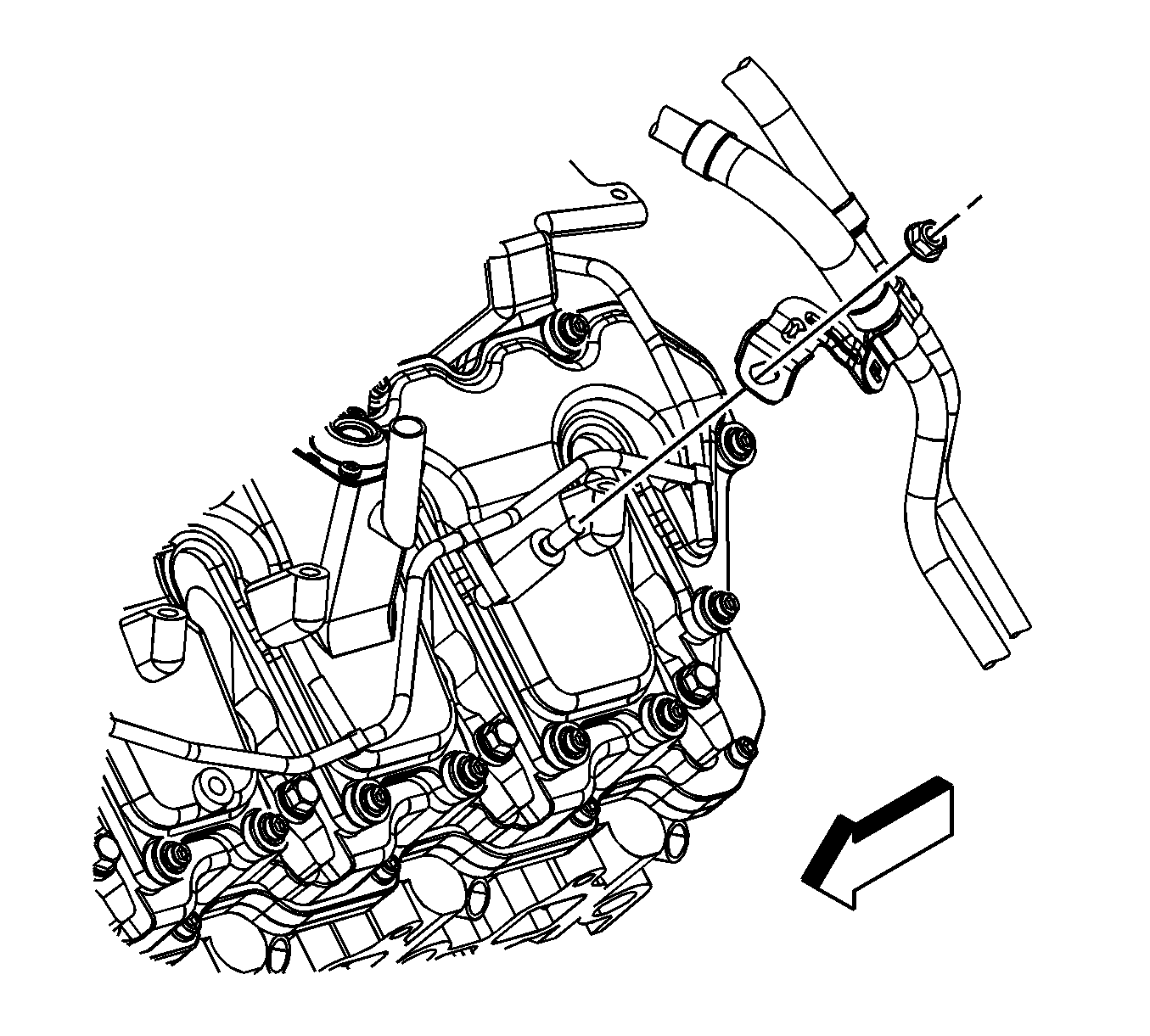
- Remove the fuel line bracket nut.
- Remove the fuel line bracket from the stud.
- Remove the engine wiring harness clip from the fuel line bracket.
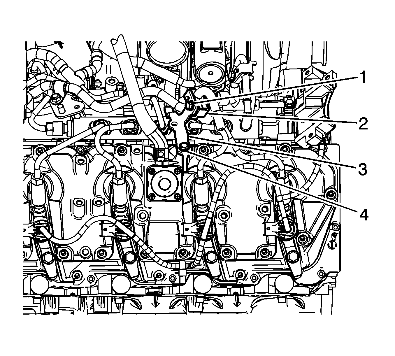
- Remove the fuel line bracket bolts (1 and 4), clamp (2), and bracket (3).
- Prior to removing the fuel injector pipes, use compressed air to blow any debris from between the injector line and fittings. Wipe the fittings clean of debris.
- Spray lithium grease, GM P/N 12346293 or equivalent, between the fuel injector line and fittings to assist in containing any debris during removal.
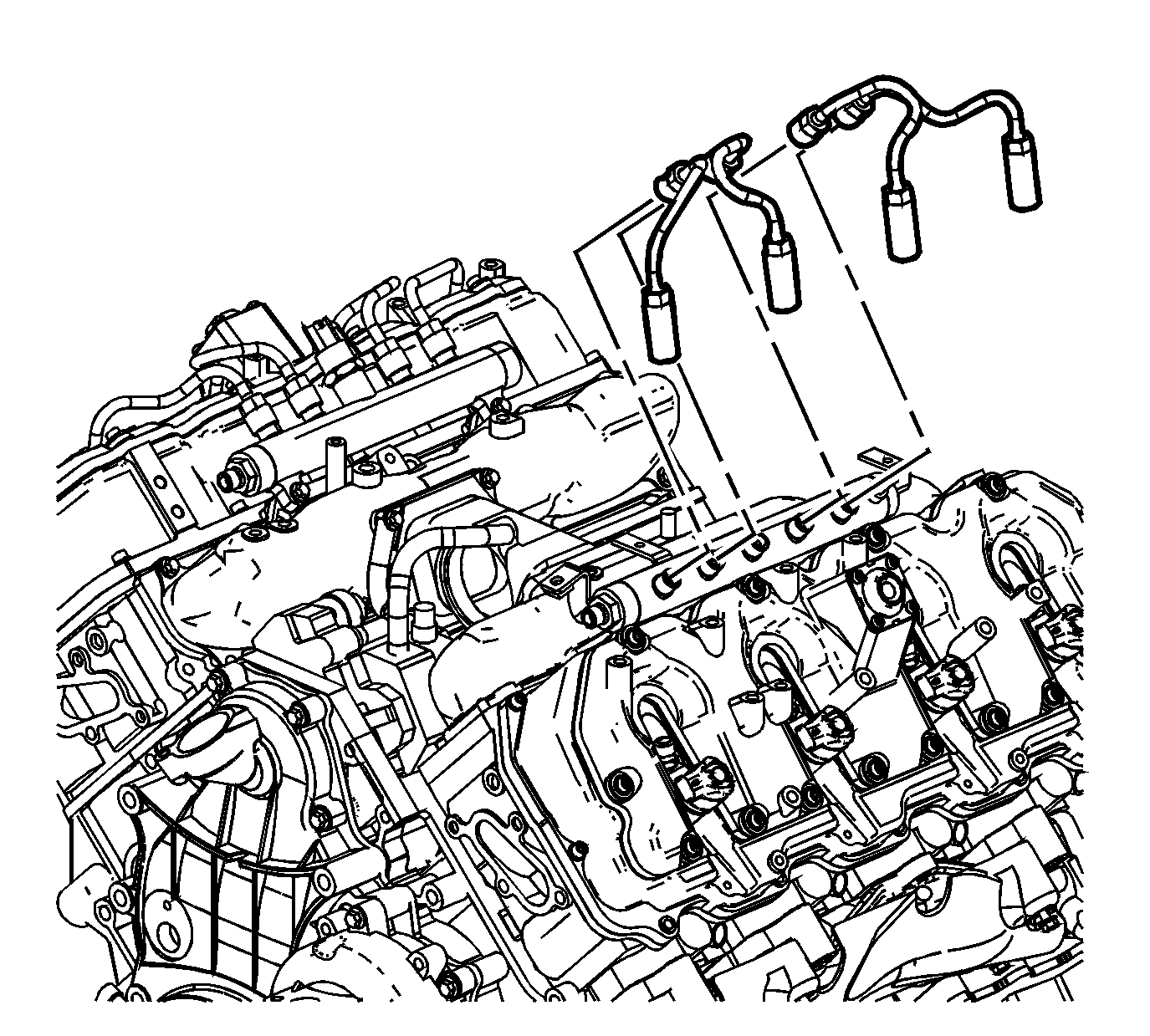
- Remove the left fuel injector pipes.


Caution: DO NOT use compressed air to clean debris from the fuel injector inlet after the fuel line is removed. Using compressed air can allow debris to enter the fuel injector inlet and damage the fuel injector.
Installation Procedure
Caution: Ensure proper torquing of the fuel injector line. An under-torqued fuel injector line will not seal properly and an over-torqued fuel injector line may damage the fuel injector fitting. An improperly sealed or damaged fuel injector line or fuel injector fitting will cause a fuel leak.
- Install the fuel injector pipes.
- Position the fuel line bracket (3) to the valve rocker arm cover, and install the clamp (2) and bolts (1 and 4).
- Install the engine wiring harness clip to the fuel line bracket.
- Install the fuel line bracket to the stud.
- Install the fuel line bracket nut.
- Connect the chassis fuel feed and return line quick connect fittings to the engine fuel feed and return pipes. Refer to Metal Collar Quick Connect Fitting Service.
- Install the glow plug control module and bracket. Refer to Glow Plug Control Module Replacement.
- Install the water outlet. Refer to Water Outlet Tube Replacement.
- Install the charge air cooler inlet pipe. Refer to Charge Air Cooler Inlet Pipe Replacement.
- Prime the fuel system. Refer to Fuel System Priming.
- Start the engine. If the engine stalls, repeat the above step.
- Once the engine starts, inspect for fuel leaks.
Caution: Refer to Fastener Caution in the Preface section.

Tighten
Tighten the fittings to 41 N·m (30 lb ft).

Tighten
Tighten the bolts to 24 N·m (18 lb ft).

Tighten
Tighten the nut to 21 N·m (15 lb ft).
