Special Tools
| • | J 8092 Universal Driver Handle 3/4 x 10 inch |
| • | J 8608 Pinion bearing Cup Installer |
| • | J 24433 Pinion Bearing Installer |
| • | J 37624 Pinion Bearing Installer |
| • | J 44414 Pinion Oil Seal Installer |
Removal Procedure
- Raise and support the vehicle. Refer to Lifting and Jacking the Vehicle.
- Drain the axle lubricant. Refer to Rear Axle Lubricant Replacement.
- Remove the rear axle shafts. Refer to Rear Axle Shaft and/or Gasket Replacement.
- Remove the rear propeller shaft.
- Remove the drive pinion flange/yoke and/or oil seal. Refer to Drive Pinion Flange/Yoke and/or Oil Seal Replacement.
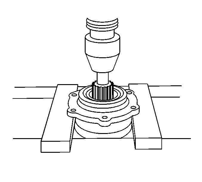
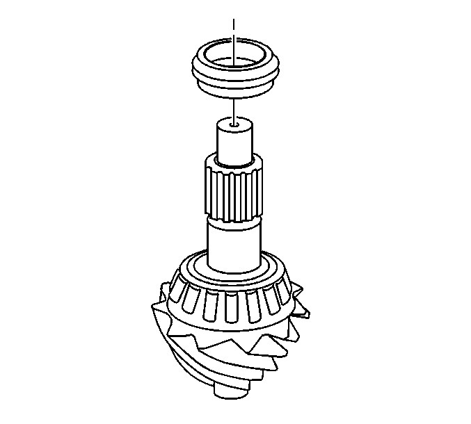
- Using a hydraulic press and an appropriate tool, remove the pinion.
- Remove the collapsible spacer.
- Using a hammer and a brass drift in the slots provided, remove the outer pinion bearing cup.
- Using a hammer and a brass drift in the slots provided, remove the inner pinion bearing cup.
Note: Observe and mark the positions of all the driveline components, relative to the propeller shaft and the axles, prior to disassembly. These components include the propeller shafts, drive axles, pinion flanges, output shafts, etc. Reassemble all the components in the exact places in which you removed the parts. Follow any specifications, torque values, and any measurements made prior to disassembly.
| • | For vehicles equipped with the one piece propeller shaft, refer to One-Piece Propeller Shaft Replacement. |
| • | For vehicles equipped with the two piece propeller shaft, refer to Two-Piece Propeller Shaft Replacement. |
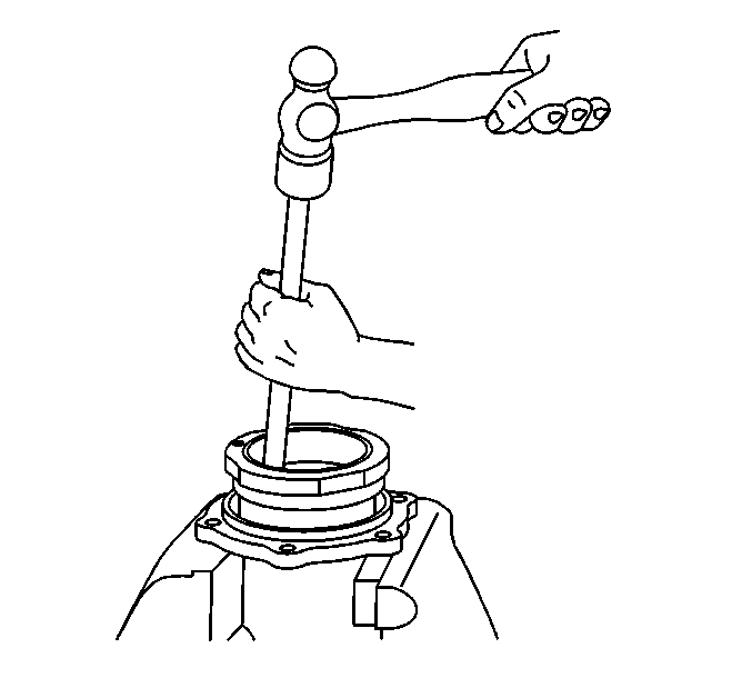
Note: When performing the following service procedure, move the drift back and forth between one side of the cup and the other in order to work the cups out of the retainer evenly.
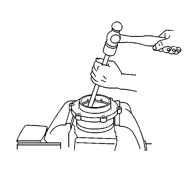
Note: When performing the following service procedure, move the drift back and forth between one side of the cup and the other in order to work the cups out of the retainer evenly.
Installation Procedure
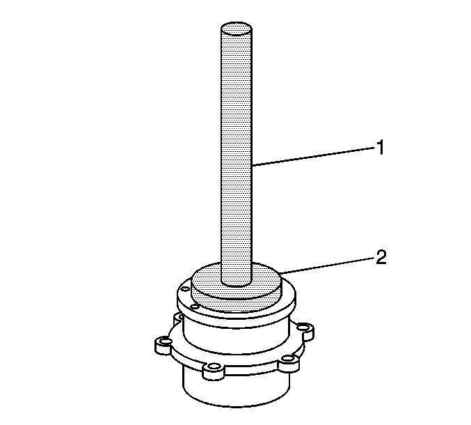
- Using the J 37624 (2) and the J 8092 (1), Install the inner pinion bearing cup into the pinion gear bearing retainer.
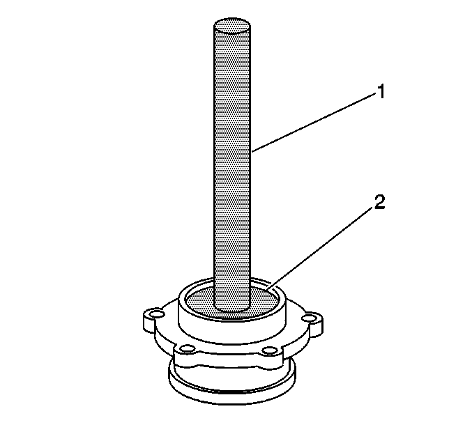
- Using the J 8608 (2) and the J 8092 (1), install the outer pinion bearing cup into the pinion gear bearing retainer.
- Apply sealant to surface of the selective shim. Refer to Adhesives, Fluids, Lubricants, and Sealers.
- Install the pinion gear bearing retainer and bolts tighten to 88 N·m (65 lb ft)..
- Install the drive pinion flange/yoke and/or oil seal. Refer to Drive Pinion Flange/Yoke and/or Oil Seal Replacement.
- Install the propeller shaft.
- Install the rear axle shafts. Refer to Rear Axle Shaft and/or Gasket Replacement.
- Fill the axle with axle lubricant. Refer to Rear Axle Lubricant Replacement.
- Remove the support and lower the vehicle.
Caution: Refer to Fastener Caution in the Preface section.
| • | For vehicles equipped with the one piece propeller shaft, refer to One-Piece Propeller Shaft Replacement. |
| • | For vehicles equipped with the two piece propeller shaft, refer to Two-Piece Propeller Shaft Replacement. |
