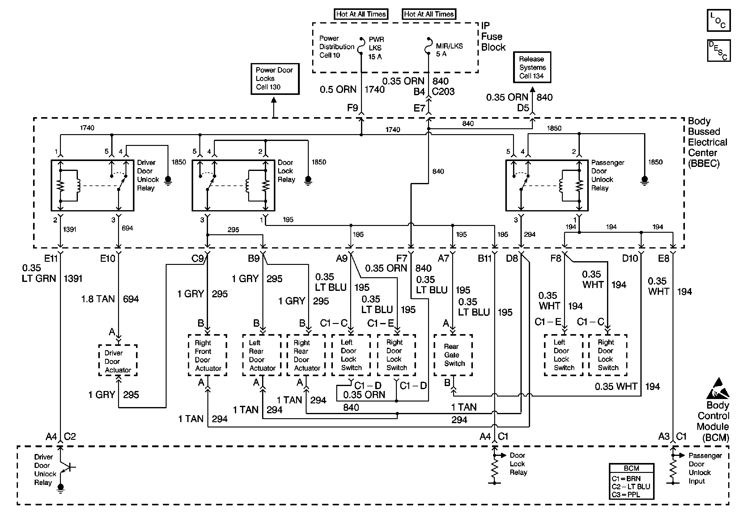
For wiring diagrams, refer to
Cell 51: DTC B3137, B3138, B3147, B3148 -- Power Door Locks

in Body Control System Schematics.
Circuit Description
The body control module (BCM) monitors and supplies an output voltage on CKT 194. When the BCM receives an unlock signal from the remote control door lock receiver to unlock the doors, the BCM supplies voltage to the lock relay and unlocks the passenger door. The BCM will set DTC B3147 as a current code if the following conditions exist:
| • | CKT 194 is shorted to ground. |
| • | BCM receives an unlock command from the remote control door lock receiver |
Conditions for Setting the DTC
| • | The BCM receives an unlock signal to unlock the passenger door from the remote control door lock receiver module and CKT 194 is shorted to ground. |
| If the BCM commands the door to unlock and CKT 194 is shorted to ground. |
| • | The system voltage is between 9.0-16.0 volts. |
| • | The above conditions exist for 184 seconds. |
Action Taken When the DTC Sets
| • | The unlock system will not unlock the passenger door from the key fob. |
| • | The door lock switches will not lock or unlock the doors. |
Conditions for Clearing the MIL/DTC
| • | A current DTC will clear after the next door unlock cycle that does not contain a fault. |
| • | A history DTC will clear after 100 consecutive ignition cycles without a fault present. |
| • | History and current DTCs can be cleared using a scan tool. |
Diagnostic Aids
| • | Always diagnose the first DTC that is listed on the scan tool. |
| • | Verify that the scan tool displays DTC B3147 as a current code before you perform diagnostics. |
| • | If a self-powered test lamp is not available, connect a test lamp to battery voltage and probe the ground circuit in order to obtain the same results. |
| • | Inspect for loose or poor connections at all of the related components. |
| • | Refer to Wiring Systems for intermittent or poor connections. |
Test Description
The numbers below refer to the step numbers on the diagnostic table.
-
This step determines if the UNLOCK relay is shorted.
-
This step determines if the LF door lock switch is shorted to ground.
-
This step determines if the RF door lock switch is shorted to ground.
-
This step determines if CKT 194 is shorted to ground.
Step | Action | Value(s) | Yes | No | ||||||
|---|---|---|---|---|---|---|---|---|---|---|
1 | Was the BCM Diagnostic System Check performed? | -- | Go to Step 2 | |||||||
Does the scan tool display B3147 as a current code? | -- | Go to Step 3 | Go to Step 9 | |||||||
Does the scan tool display B3147 as a current code? | -- | Go to Step 4 | Go to Step 7 | |||||||
Does the scan tool display B3147 as a current code? | -- | Go to Step 5 | Go to Step 8 | |||||||
5 |
Does the test lamp light? | -- | Go to Step 6 | Go to Step 10 | ||||||
Is the repair complete? | -- | Go to Step 11 | -- | |||||||
7 |
Is the repair complete? | -- | Go to Step 11 | -- | ||||||
8 |
Is the repair complete? | -- | Go to Step 11 | -- | ||||||
9 |
Is the repair complete? | -- | Go to Step 11 | -- | ||||||
10 |
Is the repair complete? | -- | Go to Step 11 | -- | ||||||
11 |
Is the repair complete? | -- | -- |
