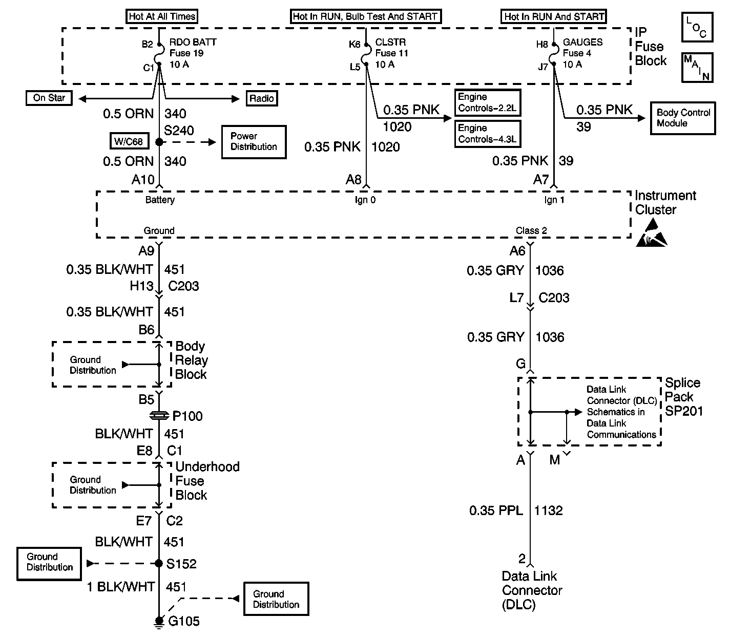
Circuit Description
The IPC inspects for a low Ignition 0 voltage when the engine is running. If the Ignition 0 is low, DTC B1367 is set. The Ignition 0 is a switched battery input to the IPC. The ignition should be high/hot whenever the ignition switch is in the following positions:
| • | UNLOCK |
| • | RUN |
| • | CRANK |
The switch should be low in the following positions:
| • | LOCK |
| • | ACCESSORY |
Conditions for Setting the DTC
The DTC sets if the voltage at the IPC connector terminal A8 is less than 3 volts for more than 1 second while the engine is running.
Conditions for Clearing the MIL/DTC
| • | A history DTC will clear after 100 consecutive fault free ignition cycles. |
| • | Use a scan tool in order to clear history and current DTCs. |
Diagnostic Aids
| • | An Intermittent condition may be caused by the following conditions: |
| - | A poor connection |
| - | A break in the wire insulation that exposes the internal wire |
| - | A wire broken inside the insulation |
| • | The IPC odometer and the PRNDL displays will not be illuminated and the IPC will not communicate with the scan tool if the following conditions exist: |
| - | The ignition 0 voltage is low at IPC connector pin A8 |
| - | The engine is not running. |
| • | The season odometer will display if the tripometer switch is pressed and the IPC will communicate with the scan tool until the tripometer switch is released. |
| • | DTC 1367 may be read by the scan tool as a history code if the fuse was recently replaced in the CKT 1020 or an open or short to ground was repaired in the CKT 1020. |
Test Description
The number(s) below refer to the step number(s) on the diagnostic table.
Step | Action | Value(s) | Yes | No |
|---|---|---|---|---|
1 | Was the IPC Diagnostic System Check performed? | -- | Go to Step 2 | |
2 |
Is an intermittent connection present? | -- | Go to Step 3 | Go to Step 4 |
3 | Repair the intermittent connection. Is the repair complete? | -- | Go to Step 4 | -- |
4 | Clear the IPC DTCs using a scan tool. Refer to Clearing DTCs. Is the repair complete? | -- | -- |
