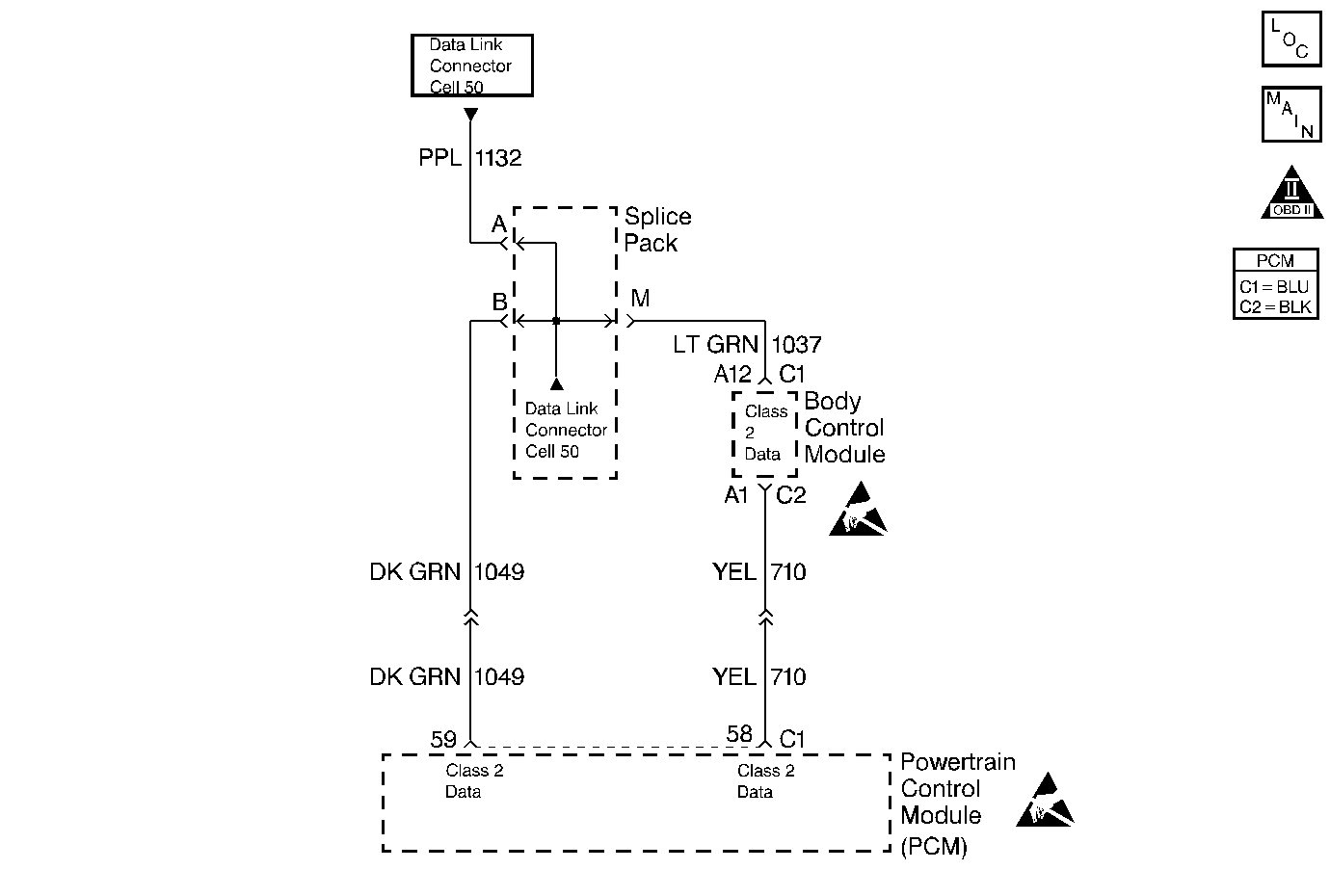
Circuit Description
The PCM identifies an engine misfire by detecting the variations in crankshaft speed. The crankshaft speed variations can also occur when a vehicle is operated over a rough surface. The ABS (Anti-Lock Brake System) can detect when the vehicle is on a rough surface based on the wheel acceleration/deceleration data supplied by each wheel speed sensor. The EBCM (Electronic Brake Control Module) over the Class 2 serial data line sends this information to the PCM. The PCM then uses this information in order to determine if the crankshaft variations are being caused by an actual engine misfire or from being driven on a rough surface.
Whenever the ABS is found to be malfunctioning, the PCM will still continue to detect for misfire. However, if a misfire DTC is set, this additional DTC P1380 will also set, indicating that rough surface data was not usable during the misfire detection due to the ABS malfunction.
Conditions for Running the DTC
| • | A Misfire DTC has been set. |
| • | The vehicle speed is more than 5 mph (8 km/h). |
Conditions for Setting the DTC
The PCM received no ABS information from the EBCM for 2.5 seconds.
Action Taken When the DTC Sets
| • | The PCM records the operating conditions at the time the diagnostic fails. The Failure Records buffers stores this information. |
| • | A history DTC is stored. |
Conditions for Clearing the DTC
| • | A History DTC clears after 40 consecutive warm up cycles without a fault. |
| • | Use a scan tool to clear the DTCs. |
Diagnostic Aids
The setting of this DTC indicates that a misfire was detected and that the PCM could not determine if the detected misfire was true or due to operating the vehicle on a rough surface. A misfire can be a true misfire with or without setting this DTC. Check the EBCM for poor connections at the Class 2 serial data terminals. Be sure no true misfire exists after repairing the cause of this DTC.
An intermittent may be caused by any of the following conditions:
| • | A poor connection |
| • | Rubbed through wire insulation |
| • | A broken wire inside the insulation |
Thoroughly check any circuitry that is suspected of causing the intermittent complaint. Refer to Intermittents and Poor Connections Diagnosis in Wiring Systems.
If a repair is necessary, refer to Wiring Repairs or Connector Repairs in Wiring Systems.
Test Description
The numbers below refer to the step numbers on the Diagnostic Table.
-
The Powertrain OBD System Check prompts the technician to complete some basic checks and store the Freeze Frame and Failure Records data on the scan tool if applicable. This creates an electronic copy of the data taken when the malfunction occurred. The information is then stored on the scan tool for later reference.
-
Be careful to clear only DTCs and not the captured information stored on the scan tool. The scan tool will issue a warning if this is about to happen.
-
Refer to the ABS portion of the service manual for ABS DTCs and repairs. Performing the ABS Diagnostic System Check is the first step in diagnosing a serial data problem.
-
A DTC P1381 being reset indicates that the PCM is not receiving serial data from the EBCM due to a EBCM problem.
-
When DTC P1381 is set, ABS serial data should not be able to be displayed.
-
Repair any condition that is causing a misfire by following the table for any DTC that has set.
-
The replacement PCM must be programmed and the Crankshaft Position System Variation Learn Procedure must be preformed. Refer to the latest Techline procedure for PCM programming.
Step | Action | Value(s) | Yes | No |
|---|---|---|---|---|
Did you perform the Powertrain On-Board Diagnostic (OBD) System Check? | -- | |||
2 |
Can the ABS data be displayed? | -- | ||
Did a misfire DTC set? | -- | |||
Repair the condition causing the ABS data not be displayed. Is the action complete? | -- | -- | ||
Was a DTC P1381 also set? | -- | |||
Can the ABS data be displayed? | -- | |||
Repair the condition causing the misfire. Is the action complete? | -- | -- | ||
Is the action complete? | -- | -- | ||
9 |
Does the scan tool indicate that this diagnostic has ran and passed? | -- | ||
10 | Check if any additional DTCs are set. Are any DTCs displayed that have not been diagnosed? | -- | Go to the applicable DTC table | System OK |
