For 1990-2009 cars only
Removal Procedure
- Remove the left sound insulator.
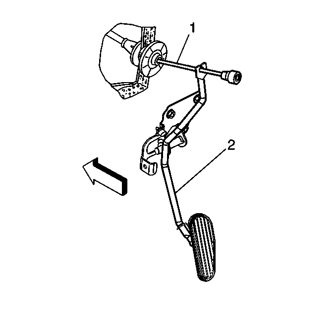
- Remove the accelerator cable (1) from the slot in pedal assembly (2).
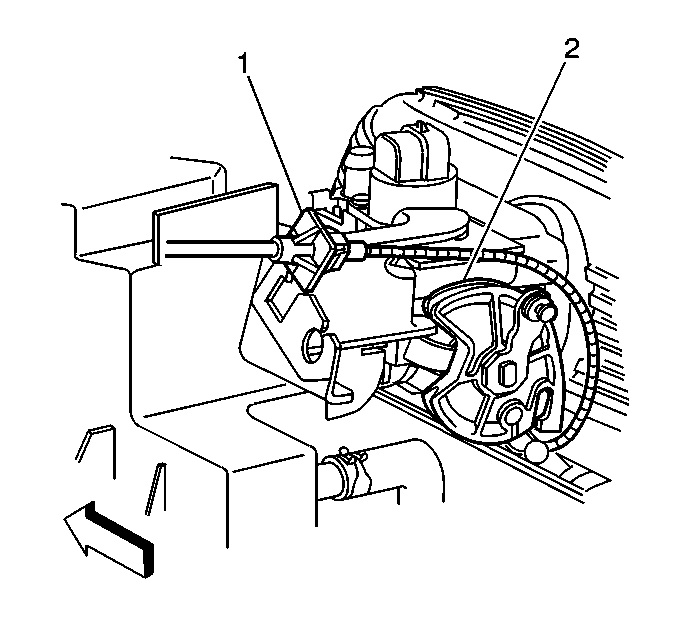
- Remove the accelerator cable from the accelerator cable bracket(1) .
- Remove the accelerator cable from the throttle lever cam (2).


Installation Procedure
- Route the cable through the accelerator cable bracket (1).
- Insert the cable lug and the cable wire into the pulley slot.
- Pull the cable conduit fitting away from the throttle lever cam (2).
- Install the tab (1) into the rectangular slot in the accelerator cable bracket.
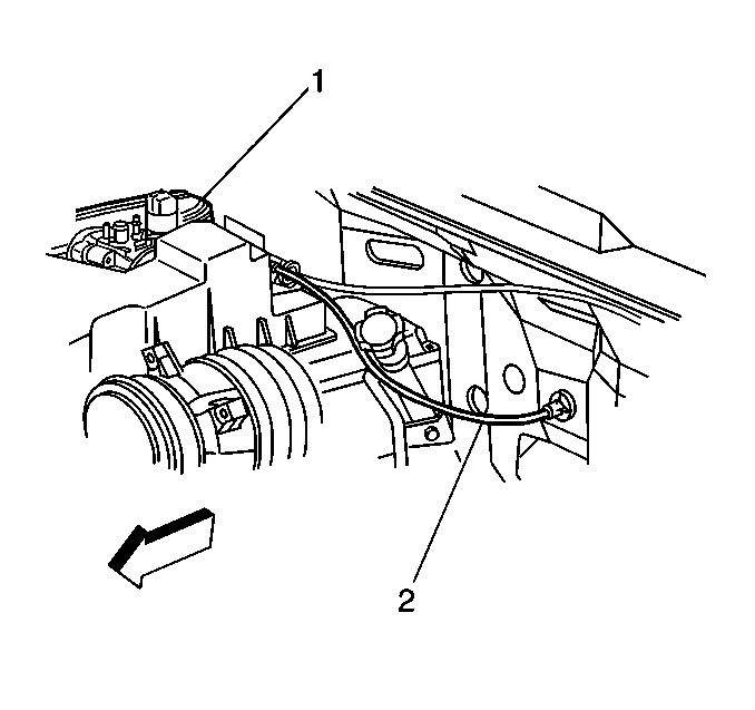
- Route cable (2) through cowl.
- Slip accelerator cable (1) through slot in the pedal assembly (2).
- Install the left sound insulator.


Important: Flexible components (hoses, wires, conduits, etc.), must not be routed within 50 mm (2.0 inches) of moving parts of accelerator linkage outboard of support unless routing is positively controlled.
Check for correct opening and closing positions by operating accelerator pedal. Make sure that the throttle valve reaches wide-open throttle position. If it does not, inspect for damaged or bent brackets, levers or other components; or, for poor carpet fit under the accelerator pedal.
