Notice: Do not use fuels containing methanol in order to prevent damage and corrosion to the fuel system.
The fuel supply is stored in the fuel tank. An electric fuel pump, which is located in the fuel tank with the fuel level sensor sending unit, pumps fuel through an in-line fuel filter to the engine. The pump provides fuel at a pressure more than is needed by the injectors. The fuel pressure regulator keeps fuel available to the injectors at a regulated pressure. The unused fuel is returned to the fuel tank by a separate line.
Fuel Tank
The fuel tank, at the rear of the underbody, is held in place by 2 metal straps. Anti-squeak pieces are used on top of the tank to reduce rattles.
Filler Neck
In order to help prevent refueling with leaded gasoline, the fuel filler neck on a gasoline engine vehicles has a built-in restrictor and deflector. The opening in the restrictor will only admit the smaller unleaded gas nozzle spout, which must be fully inserted to bypass the deflector.
Attempted refueling with a leaded gas nozzle or failure to fully insert the unleaded gas nozzle results in gasoline splashing back out of the filler neck.
Fuel Filler Cap
Notice: Use a fuel tank filler pipe cap with the same features as the original when a replacement is necessary. Failure to use the correct fuel tank filler pipe cap can result in a serious malfunction of the fuel system.
The fuel tank filler neck is equipped with a quarter-turn type fuel filler cap. A built in ratchet type torque limiting device prevents over tightening. In order to install, turn the fuel filler cap clockwise until a clicking noise is heard. This signals that the correct torque has been reached and the fuel filler cap is fully seated. A fuel filler cap that is not fully seated, may cause a malfunction in the emission system.
Modular Fuel Sender Assembly

The modular fuel sender assembly mounts in the top of the fuel tank and is spring loaded to the bottom. The modular fuel sender assembly is designed to:
| • | Provide optimum fuel level in the internal fuel reservoir during all fuel tank levels and driving conditions. |
| • | Improve the measuring accuracy of the fuel tank level. |
| • | Filters coarse contaminates from the fuel. |
| • | House fuel pump and helps prevent fuel pump noise. |
| • | Include a check valve to inhibit back flow of fuel from fuel system. |
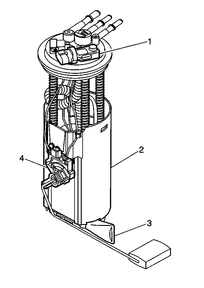
The fuel sender consists of the following serviceable components:
| • | A fuel strainer (3) |
| • | A fuel level sensor (4) |
| • | A fuel tank pressure sensor (1) |
Fuel Pump

An electric fuel pump located in the modular sender assembly (2) is used to provide fuel pressure. To control fuel pump operation, a fuel pump relay and fuel pump switch are used. When the ignition switch is turned to RUN position, the fuel pump relay activates the electric fuel pump for approximately two seconds to prime the fuel injectors. If the PCM does not receive reference pulses after this time, the PCM opens the fuel pump relay voltage circuit. The relay will reactivate the fuel pump when the PCM receives reference pulses.
Fuel Tank Pressure Sensor

The fuel tank pressure sensor (1) is mounted on top of the modular fuel sender. The sensor measures the difference between the fuel vapor pressure (or vacuum) in the fuel tank and the outside air pressure. A three wire electrical harness connects it to the powertrain control module (PCM). The PCM supplies a 5 volt reference signal and ground to the sensor. The sensor will return a voltage between 0.1 volts and 4.9 volts back to the PCM depending on the fuel vapor pressure in the fuel tank. When the fuel pressure in the fuel tank is equal to the outside air pressure, such as when the fuel cap is removed, the output voltage will be 1.3 volts to 1.7 volts.
Fuel Pump Strainer

A woven plastic strainer (3) is located on the lower end of the fuel sender. This filter prevents dirt from entering the fuel pipe and also stops water unless the filter becomes completely submerged in water. This fuel pump strainer is self cleaning and normally requires no maintenance. Fuel stoppage at this point indicates that the fuel tank contains an abnormal amount of sediment or water. Therefore, should this occur, the fuel tank should be removed and thoroughly cleaned and the fuel pump strainer replaced.
Fuel Level Sensor

The fuel sensor (4) is attached to the modular fuel sender. The resistance of the fuel level sensor changes with the fuel by means of a rheostat. As the position of the float varies with the fuel level, the rheostat produces a variable resistance. The fuel gauge converts this varible resistance into the fuel level reading displayed on the instrument panel.
Fuel And Vapor Pipes
The fuel feed and return pipes and hoses extend from the fuel pump and the sender to the injection unit. The fuel feed and return pipes and hoses are routed along the frame side member.
The vapor pipe and hoses extend from the fuel pump and the sender unit to the evaporative emission (EVAP) control vapor canister.
In-Line Fuel Filter

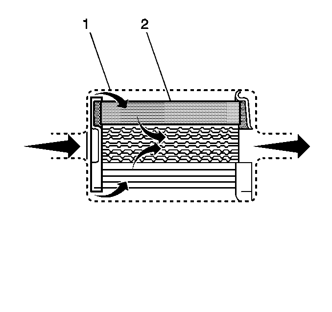
A stainless steel in-line fuel filter is used in the fuel feed line ahead of the fuel injection system. The steel filter housing (1) is constructed to withstand maximum fuel system pressure, exposure to fuel additives, and changes in temperature. The filter element (2) is made of paper, and is designed to trap particles in the fuel that may damage the injection system.
