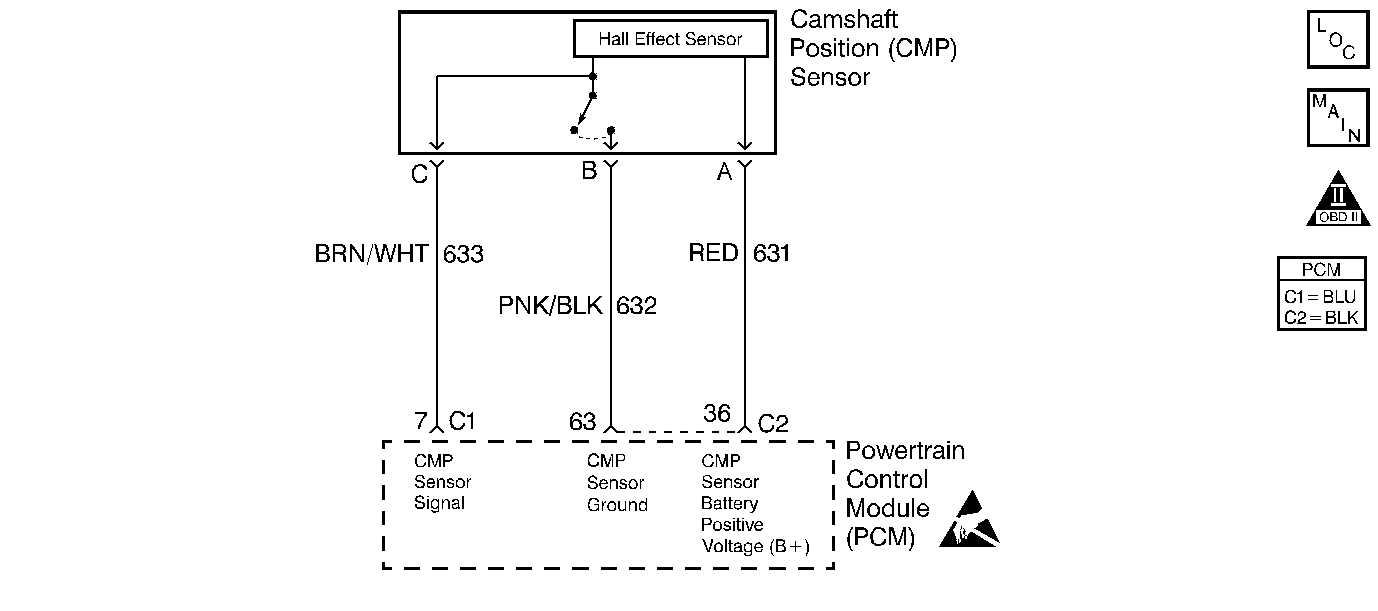
Circuit Description
The camshaft position (CMP) sensor indicates the camshaft position so that the powertrain control module (PCM) can determine which cylinder is misfiring when a misfire is present. Whenever the PCM receives an intermittent signal from the CMP, then the CMP resync counter will increment. In order to set a DTC, the PCM must see a minimum number of resyncs within a calculated time.
Conditions for Running the DTC
The engine is running.
Conditions for Setting the DTC
The PCM sees more than 15 CMP sensor resyncs in 256 seconds (4 minutes 16 seconds).
Action Taken When the DTC Sets
| • | The malfunction indicator lamp (MIL) will illuminate after 2 consecutive ignition cycles in which the diagnostic runs with the malfunction present. |
| • | The PCM will record the operating conditions at the time that the diagnostic fails. The Freeze Frame and Failure Records buffers will store this information. |
| • | A history DTC stores. |
Conditions for Clearing the MIL/DTC
| • | The MIL will turn OFF after 3 consecutive ignition cycles in which the diagnostic runs without a fault. |
| • | A history DTC will clear after 40 consecutive warm up cycles without a fault. |
| • | A scan tool can clear the DTCs. |
Diagnostic Aids
| • | Thoroughly check any circuitry that is suspected as causing the intermittent complaint for the following conditions: |
| - | Improper mating |
| - | Broken locks |
| - | Improperly formed or damaged terminals |
| - | Physical damage to the wiring harness |
| - | A poor connection |
| - | Rubbed through wire insulation |
| - | Broken wire inside the insulation |
| • | Whenever the PCM sees less than 15 resyncs in 256 seconds, the counter is reset to 0. Anytime a poor connection is present, the cam sensor reference activity counter will stop incrementing and the cam sensor resync counter will increment. |
Test Description
The step numbers below refer to the step numbers in the diagnostic table.
-
If any other DTCs are set go there first.
-
If the CMP resync counter stops incrementing when the CMP sensor is disconnected, the problem is in the sensor or the sensor connector.
-
This step checks for a short to voltage on the CMP sensor signal circuit.
-
This step is to check for electromagnetic interference (EMI) in the wiring harness.
Step | Action | Values | Yes | No |
|---|---|---|---|---|
1 | Did you perform the Powertrain On-Board Diagnostic (OBD) System Check? | -- | ||
Are any other CMP sensor DTCs set? | -- | Go to applicable DTC table | ||
3 |
Is the resync counter incrementing | -- | ||
4 |
Does DTC P0341 reset? | -- | Go to Diagnostic Aids | |
Is the CMP sensor resync counter or active counter incrementing? | -- | |||
Is the voltage above the specified value? | 1 V | |||
7 | Repair the short to voltage on the CMP sensor signal circuit. Refer to Wiring Repairs in Wiring Systems. Is the action complete? | -- | -- | |
Is the Hz reading above the specified value? | 0.0 Hz | |||
9 | Isolate and repair the circuit or component that induced the Hz reading above 0.0 Hz. Refer to Wiring Repairs or Connector Repairs in Wiring Systems. Is the action complete? | -- | -- | |
10 | Inspect the CMP sensor connector for internal shorting or water intrusion and correct if necessary. Refer to Connector Repairs in Wiring Systems. Was a repair necessary? | -- | ||
11 |
Was a repair necessary? | -- | ||
12 | Replace the CMP sensor. Refer to Camshaft Position Sensor Replacement . Is the action complete? | -- | -- | |
13 |
Important: The replacement PCM must be programmed. Replace the PCM. Refer to Powertrain Control Module Replacement/Programming . Is the action complete? | -- | -- | |
14 |
Does the scan tool indicate the diagnostic Passed? | -- | ||
15 | Does the scan tool display any additional undiagnosed DTCs? | -- | Go to applicable DTC table | System OK |
