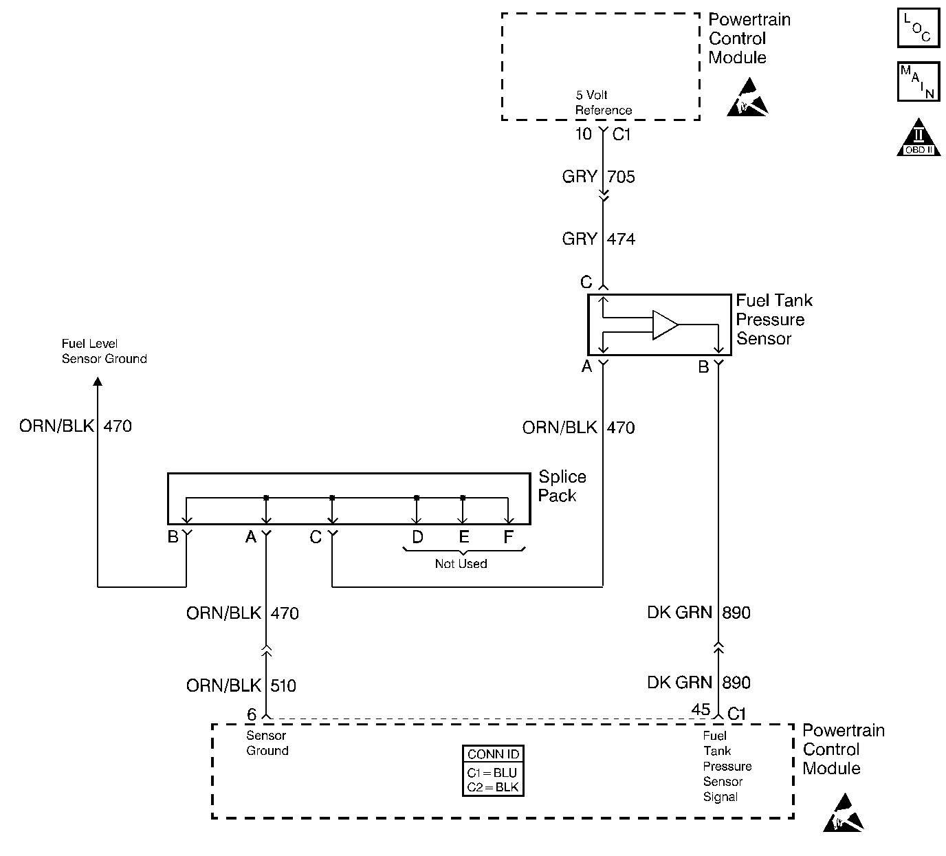
Circuit Description
The fuel tank pressure sensor is used in order to monitor the vacuum levels in the fuel tank. The fuel tank pressure sensor responds to the changes in the fuel tank pressure or vacuum. The signal voltage to the powertrain control module (PCM) varies from a minimum of about 0.2 volts with pressure in the fuel tank to above 4.0 volts with a high vacuum in the fuel tank.
Conditions for Running the DTC
The engine is running.
Conditions for Setting the DTC
The fuel tank pressure sensor voltage is lower than 0.1 volt for more than 25 seconds.
Action Taken When the DTC Sets
| • | The malfunction indicator lamp (MIL) will illuminate. |
| • | The PCM will record the operating conditions at the time that the diagnostic fails. The Freeze Frame and Failure Records buffers will store this information. |
| • | A history DTC stores. |
Conditions for Clearing the MIL/DTC
| • | The malfunction indicator lamp (MIL) will turn OFF after 3 consecutive ignition cycles in which the diagnostic runs without a fault. |
| • | A history DTC will clear after 40 consecutive warm up cycles without a fault. |
| • | Use a scan tool to clear the DTCs. |
Test Description
The numbers below refer to the step numbers on the diagnostic table.
-
This step tests the signal circuit, of the fuel tank pressure sensor, for a short to a voltage.
-
This step tests the ground circuit of the fuel tank pressure sensor.
-
This step tests the 5 volt reference circuit of the fuel tank pressure sensor. If the DMM displays a voltage greater than 5 volts, repair the short to voltage.
Step | Action | Values | Yes | No |
|---|---|---|---|---|
1 | Did you perform the Powertrain On-Board Diagnostic (OBD) System Check? | -- | ||
Is the fuel tank pressure sensor voltage above the specified value? | 4.3V | |||
3 |
Does the DTC fail this ignition? | -- | Go to Intermittent Conditions | |
Is the fuel tank pressure sensor voltage below the specified value? | 1V | |||
Probe the ground circuit of the fuel tank pressure sensor with a test lamp connected to B+. Refer to Probing Electrical Connectors in Wiring Systems. Is the test lamp illuminated? | -- | |||
Measure the voltage from the fuel tank pressure sensor 5 volt reference circuit with a DMM. Refer to Circuit Testing in Wiring Systems. Is the voltage near the specified value? | 5V | |||
7 | Test the fuel tank pressure sensor signal circuit for a short to voltage or a short to a 5 volt reference circuit. Refer to Circuit Testing and Wiring Repairs in Wiring Systems. Did you find and correct the condition? | -- | ||
8 | Test the ground circuit of the fuel tank pressure sensor for an open. Refer to Circuit Testing and Wiring Repairs in Wiring Systems. Did you find and correct the condition? | -- | ||
9 | Inspect for poor connections at the harness connector of the PCM. Refer to Testing for Intermittent Conditions and Poor Connections and Connector Repairs in Wiring Systems. Did you find and correct the condition? | -- | ||
10 | Inspect for poor connections at the harness connector of the fuel tank pressure sensor. Refer to Testing for Intermittent Conditions and Poor Connections and Connector Repairs in Wiring Systems. Did you find and correct the condition? | -- | ||
11 | Repair the 5 volt reference circuit for a short to voltage. Refer to Wiring Repairs in Wiring Systems. Did you complete the repair? | -- | -- | |
12 | Replace the fuel tank pressure sensor. Refer to Fuel Tank Pressure Sensor Replacement . Did you complete the replacement? | -- | -- | |
13 | Replace the PCM. Refer to Powertrain Control Module Replacement/Programming . Did you complete the replacement? | -- | -- | |
14 |
Does the DTC run and pass? | -- | ||
15 | Select the Capture Info option and the Review Info option using the scan tool. Does the scan tool display any DTCs that you have not diagnosed? | -- | Go to the applicable DTC table | System OK |
