Removal Procedure
- Disconnect the negative battery cable. Refer to Battery Negative Cable Disconnection and Connection in Engine Electrical.
- Remove the radiator. Refer to Radiator Replacement in Engine Cooling.
- Remove the A/C condenser, if equipped. Refer to Condenser Replacement in Heating Ventilation and Air Conditioning.
- Remove the cylinder head. Refer to Cylinder Head Replacement .
- Remove the engine front cover. Refer to Engine Front Cover Replacement .
- Remove the valve lifters. Refer to Valve Lifter Replacement .
- Rotate the crankshaft until the number 1 piston is at top dead center (TDC) on the compression stroke.
- Remove the oil pump drive. Refer to Oil Pump Drive Replacement .
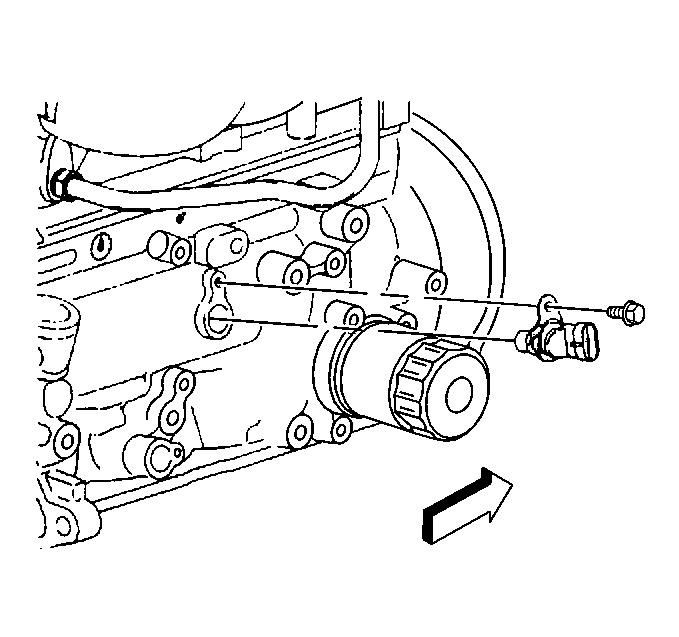
- Remove the camshaft position sensor. Refer to Camshaft Position Sensor Replacement in Engine Controls 2.2 L (L43).
- Remove the camshaft sprocket and the camshaft timing chain. Refer to Timing Chain and Sprocket Replacement .
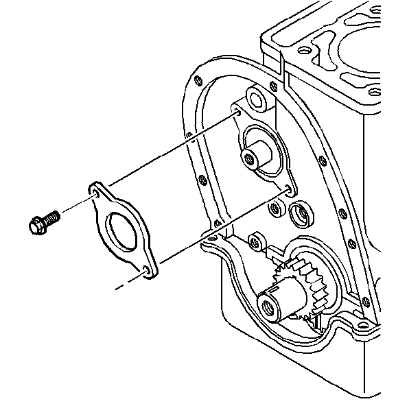
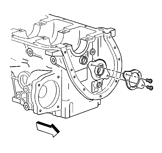
- Remove the camshaft thrust plate bolts.
- Remove the camshaft position sensor.
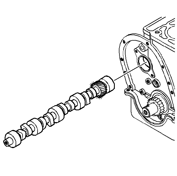
- Remove the camshaft.


Important: Do not damage the camshaft bearings while removing the camshaft.
Inspect the camshaft for wear or damage. Refer to Camshaft and Bearings Cleaning and Inspection in Engine Mechanical-2.2 L (L 43) Unit Repair.
Installation Procedure
Important: If installing a new camshaft, change the engine oil and the oil filter.
- Install the camshaft.
- Coat the camshaft lobes, journals, and oil pump drive gear with engine assembly prelube (GM P/N 1052367) or equivalent.
- Handle the camshaft carefully in order to prevent damage to the camshaft bearings.
- Install the thrust plate bolts.
- Install the camshaft position sensor. Refer to Camshaft Position Sensor Replacement in Engine Controls 2.2 L (L43).
- Install the crankshaft sprocket and camshaft timing chain. Refer to Timing Chain and Sprocket Replacement .
- Install the oil pump drive. Refer to Oil Pump Drive Replacement .
- Install the engine front cover. Refer to Engine Front Cover Replacement .
- Install the valve lifters. Refer to Valve Lifter Replacement .
- Install the cylinder head. Refer to Cylinder Head Replacement .
- Install the air conditioning condenser, if equipped. Refer to Condenser Replacement in Heating Ventilation and Air Conditioning.
- Install the radiator. Refer to Radiator Replacement in Engine Cooling.
- Connect the negative battery cable. Refer to Battery Negative Cable Disconnection and Connection in Engine Electrical.

Important: If you install a new camshaft, replace all of the valve lifters.

Notice: Use the correct fastener in the correct location. Replacement fasteners must be the correct part number for that application. Fasteners requiring replacement or fasteners requiring the use of thread locking compound or sealant are identified in the service procedure. Do not use paints, lubricants, or corrosion inhibitors on fasteners or fastener joint surfaces unless specified. These coatings affect fastener torque and joint clamping force and may damage the fastener. Use the correct tightening sequence and specifications when installing fasteners in order to avoid damage to parts and systems.
Tighten
Tighten the thrust plate bolts to 12 N·m (106 lb in).
