Tools Required
J 36660-A Torque Angle Meter
Removal Procedure
- Disconnect the negative battery cable. Refer to Battery Negative Cable Disconnection and Connection in Engine Electrical.
- Drain the cooling system. Refer to Cooling System Draining and Filling in Engine Cooling.
- Remove the engine cooling fan clutch. Refer to Fan Clutch Replacement in Engine Cooling.
- Remove the engine drive belt. Refer to Drive Belt Replacement .
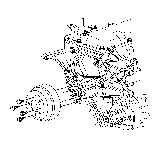
- Remove the fan pulley.
- Remove the generator. Refer to Generator Replacement in Engine Electrical.
- Remove the A/C compressor, if equipped. Refer to Air Conditioning Compressor Replacement in Heating, Ventilation and Air Conditioning.
- Remove the power steering pump. Refer to Power Steering Pump Replacement in Power Steering System.
- Remove the thermostat assembly. Refer to Engine Coolant Thermostat Replacement in Engine Cooling.
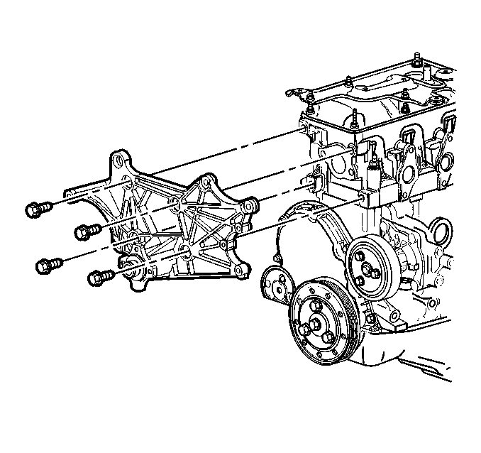
- Remove the bolts holding the accessory mounting bracket to the engine.
- Remove the accessory mounting bracket.
- Remove the exhaust manifold. Refer to Exhaust Manifold Replacement in Engine Exhaust.
- Remove the valve rocker arm cover. Refer to Valve Rocker Arm Cover Replacement .
- Remove the valve rocker arms and push rods. Refer to Valve Rocker Arm and Push Rod Replacement .
- Remove the intake manifold. Refer to Intake Manifold Replacement .
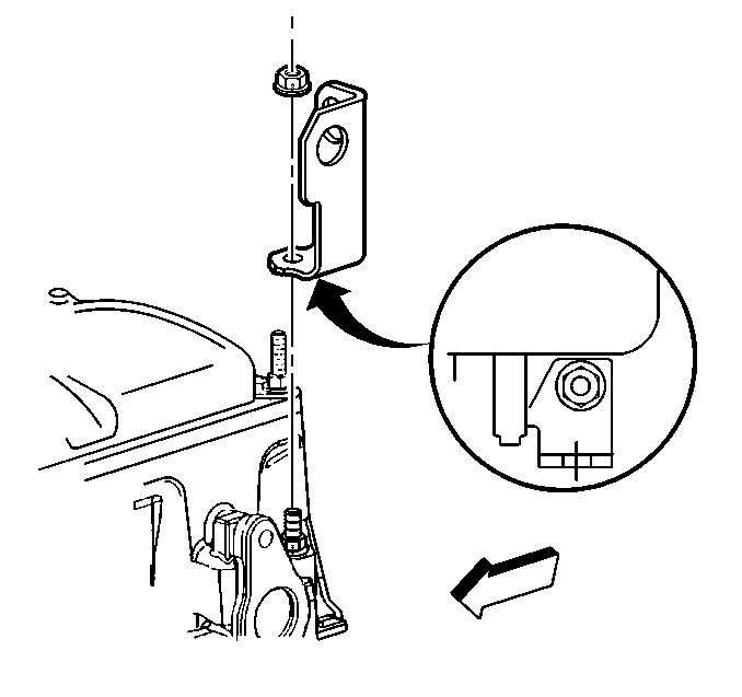
- Remove the engine lift bracket from the rear of the engine.
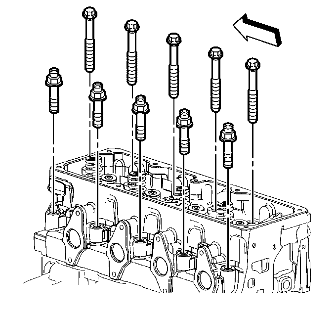
- Remove the cylinder head bolts.
- Remove the cylinder head.
- Remove and discard the cylinder head gasket.
- Clean the following areas:
- Inspect the engine block to cylinder head mating surface for the following conditions:
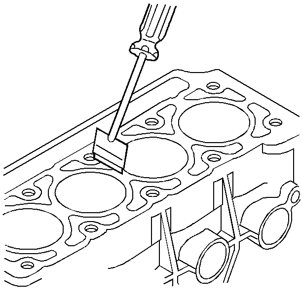
| • | Clean any carbon deposits from the combustion chambers. |
| • | Clean all traces of the old cylinder head gasket from the cylinder head and from the engine block. |
| Important: Do not use abrasive pads to clean the cylinder head or block surfaces. An abrasive pad will damage the cylinder head and block surfaces. Abrasive pads also produce a fine grit that will contaminate the engine oil. It is only necessary to remove the gasket material. Do not attempt to remove all marks from the cylinder head gasket surfaces. |
| • | Clean the cylinder head bolt threads. |
| • | Clean the threads that are in the engine block. |
| • | Nicks |
| • | Heavy scratches |
| • | Any other damage |
| • | For further service to the cylinder head refer to the following: |
| • | Cylinder Head Disassemble in Engine Mechanical - 2.2L Unit Repair |
| • | in Engine Mechanical - 2.2L Unit Repair |
| • | Valve Guide Reaming, and Valve and Seat Grinding in Engine Mechanical - 2.2L Unit Repair |
| • | Cylinder Head Assemble in Engine Mechanical - 2.2L Unit Repair |
Installation Procedure
- Install the cylinder head gasket to the block.
- Use a socket to push the cylinder head gasket over the rear dowel pin.
- Carefully guide the cylinder head into place over the dowel pins. This operation may require an assistant.
- Install the cylinder head bolts by hand.
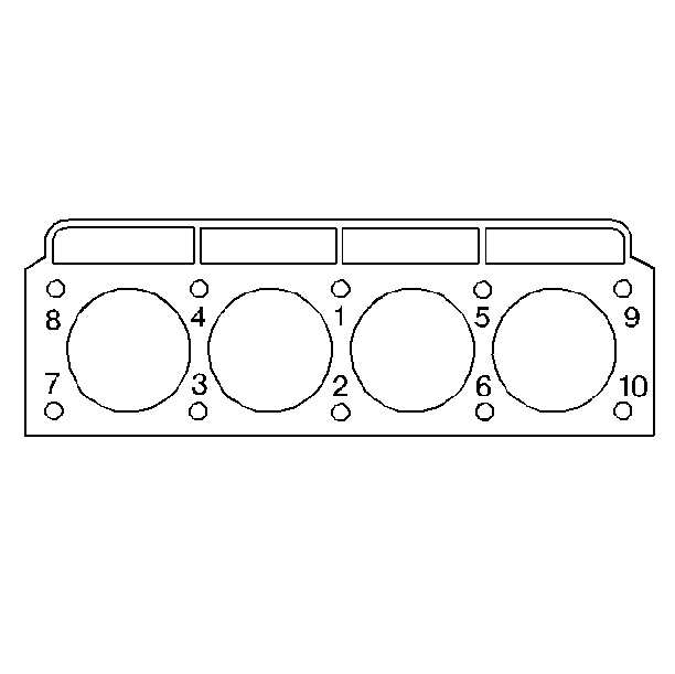
- Use the following sequence in order to tighten the cylinder head bolts:
- Install the engine lift bracket onto the rear of the engine.
- Install the intake manifold. Refer to Intake Manifold Replacement .
- Install the valve rocker arms and push rods. Refer to Valve Rocker Arm and Push Rod Replacement .
- Install the valve rocker arm cover. Refer to Valve Rocker Arm Cover Replacement .
- Install the exhaust manifold. Refer to Exhaust Manifold Replacement in Engine Exhaust.
- Install the accessory mounting bracket.
- Install the bolts holding the accessory mounting bracket to the engine.
- Install the thermostat assembly. Refer to Engine Coolant Thermostat Replacement in Engine Cooling.
- Install the A/C compressor, if equipped. Refer to Air Conditioning Compressor Replacement in Heating, Ventilation and Air Conditioning.
- Install the power steering pump. Refer to Power Steering Pump Replacement in Power Steering System.
- Install the generator. Refer to Generator Replacement in Engine Electrical.
- Install the fan pulley.
- Install the engine drive belt. Refer to Drive Belt Replacement .
- Install the engine cooling fan clutch. Refer to Fan Clutch Replacement in Engine Cooling.
- Fill the cooling system. Refer to Cooling System Draining and Filling in Engine Cooling.
- Connect the negative battery cable. Refer to Battery Negative Cable Disconnection and Connection in Engine Electrical.
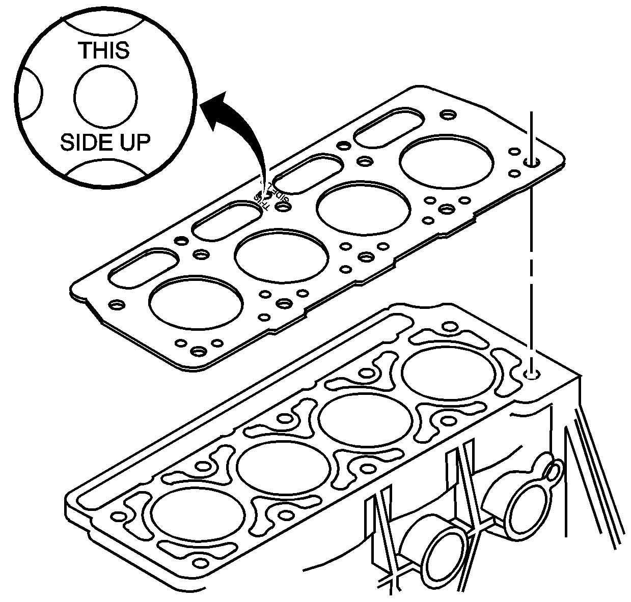
Important: Install the NEW cylinder head gasket with the words THIS SIDE UP showing.
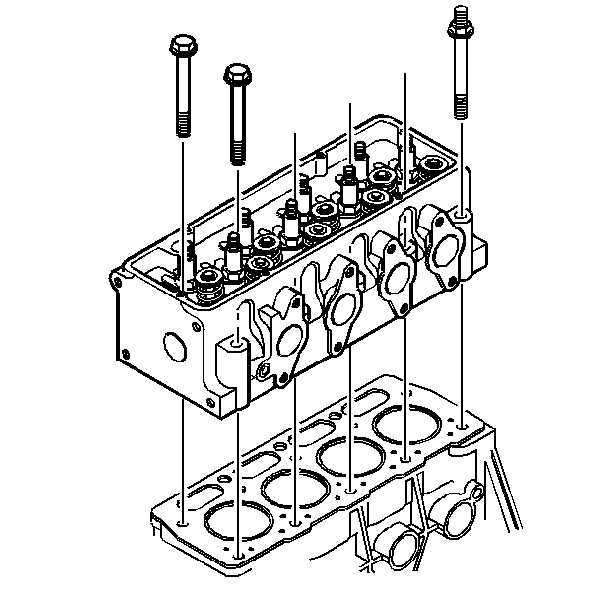

Notice: Use the correct fastener in the correct location. Replacement fasteners must be the correct part number for that application. Fasteners requiring replacement or fasteners requiring the use of thread locking compound or sealant are identified in the service procedure. Do not use paints, lubricants, or corrosion inhibitors on fasteners or fastener joint surfaces unless specified. These coatings affect fastener torque and joint clamping force and may damage the fastener. Use the correct tightening sequence and specifications when installing fasteners in order to avoid damage to parts and systems.
Tighten
| • | Tighten the long cylinder head bolts to 63 N·m (46 lb ft). |
| • | Tighten the short cylinder head bolts to 58 N·m (43 lb ft). |
| 5.1. | Tighten bolt 1 to 63 N·m (46 lb ft). |
| 5.2. | Tighten bolt 2 to 58 N·m (43 lb ft). |
| 5.3. | Tighten bolt 3 to 58 N·m (43 lb ft). |
| 5.4. | Tighten bolt 4 to 63 N·m (46 lb ft). |
| 5.5. | Tighten bolt 5 to 63 N·m (46 lb ft). |
| 5.6. | Tighten bolt 6 to 58 N·m (43 lb ft). |
| 5.7. | Tighten bolt 7 to 58 N·m (43 lb ft). |
| 5.8. | Tighten bolt 8 to 63 N·m (46 lb ft). |
| 5.9. | Tighten bolt 9 to 63 N·m (46 lb ft). |
| 5.10. | Tighten bolt 10 to 58 N·m (43 lb ft). |
| 5.11. | Use J 36660-A to tighten all the cylinder head bolts an additional 90 degrees in sequence. |

Tighten
Tighten the engine lift bracket nut to 50 N·m (37 lb ft).

Tighten
Tighten the accessory mounting bolts to 50 N·m (37 lb ft).

Tighten
Tighten the fan pulley bolts to 30 N·m (22 lb ft).
