Relay Rod Replacement RWD
Tools Required
| • | J 6627-A Tie Rod Puller |
| • | J 24319-B Steering Linkage and Tie Rod Puller |
Removal Procedure
- Raise and suitably support the vehicle with safety stands. Refer to Lifting and Jacking the Vehicle in General Information.
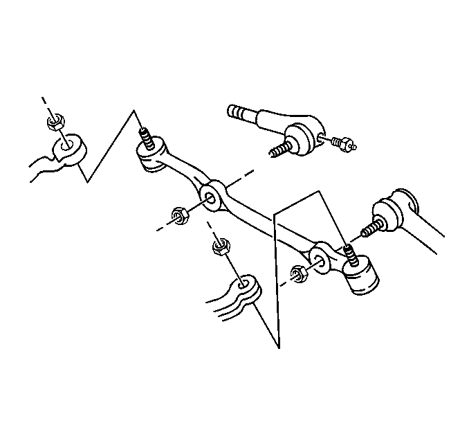
- Remove the inner tie rods ball stud nuts.
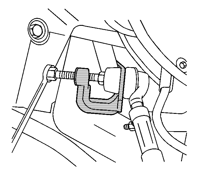
- Disconnect the inner tie rods ball studs from the relay rod using J 6627-A .
- Remove the relay rod ball stud nut at the pitman arm.
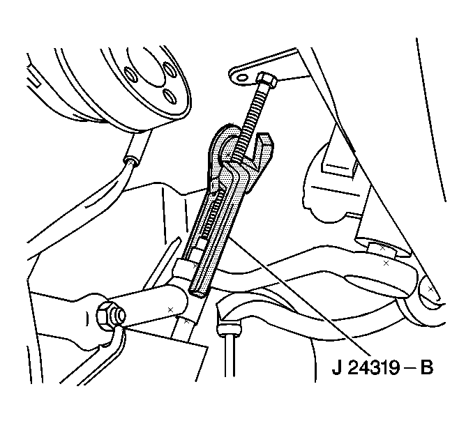
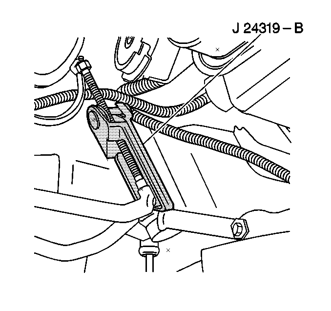
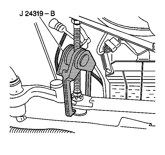
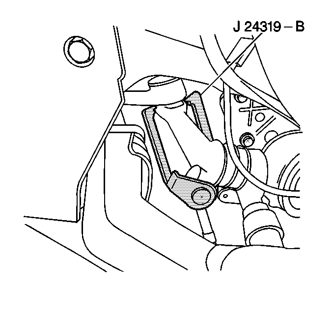
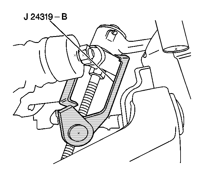
- Disconnect the relay rod ball stud from the pitman arm using J 24319-B .
- Remove the relay rod ball stud nut at the idler arm.
- Disconnect the relay rod from the idler arm usingJ 24319-B .
- Remove the relay rod.
- Inspect the following components:
- Clean the threads on the ball stud and ball stud nut.
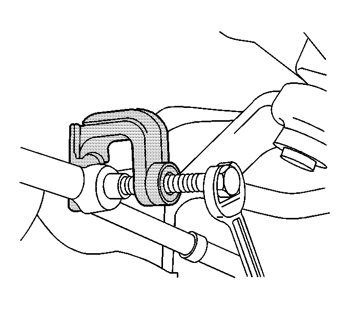
Important: Use the proper tool in order to separate all ball joints.
| • | The threads on the tie rod for damage |
| • | The threads on the tie rod end for damage |
| • | The ball stud threads for damage |
| • | The ball stud seals for excessive wear |
Installation Procedure
- Install the relay rod ball stud to the idler arm.
- Install the new nut to the relay rod ball stud at the idler arm.
- Install the relay rod ball stud to the pitman arm.
- Install the new nut to the relay rod ball stud at the pitman arm.
- Install the inner tie rod ball studs to the relay rod.
- Install the new nuts to the inner tie rod ball studs.
- Lower the vehicle.
- Adjust the front toe. Refer to Front Toe Adjustment in Wheel Alignment.
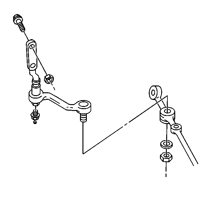
Ensure that the seal is on the stud.
Notice: Use the correct fastener in the correct location. Replacement fasteners must be the correct part number for that application. Fasteners requiring replacement or fasteners requiring the use of thread locking compound or sealant are identified in the service procedure. Do not use paints, lubricants, or corrosion inhibitors on fasteners or fastener joint surfaces unless specified. These coatings affect fastener torque and joint clamping force and may damage the fastener. Use the correct tightening sequence and specifications when installing fasteners in order to avoid damage to parts and systems.
Tighten
Tighten the relay rod ball stud nut at the idler arm to 47 N·m
(35 lb in).
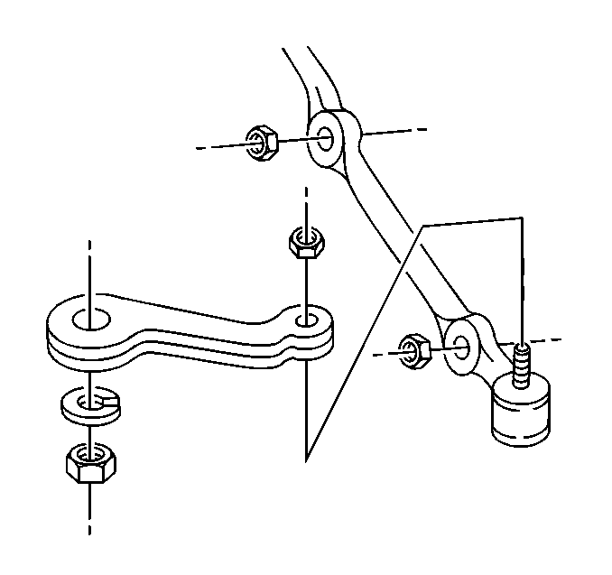
Ensure that the seal is on the stud.
Tighten
Tighten the relay rod ball stud nut at the pitman arm to 48 N·m
(36 lb ft).

Ensure that the seal is on the stud.
Tighten
Tighten the inner tie rod ball studs nuts to 47 N·m (35 lb ft).
Relay Rod Replacement 4WD
Tools Required
| • | J 6627-A Tie Rod Puller |
| • | J 24319-B Steering Linkage and Tie Rod Puller |
Removal Procedure
- Raise and suitably support the vehicle with safety stands. Refer to Lifting and Jacking the Vehicle in General Information.
- Remove the steering linkage shield. Refer to Steering Linkage Shield Replacement .
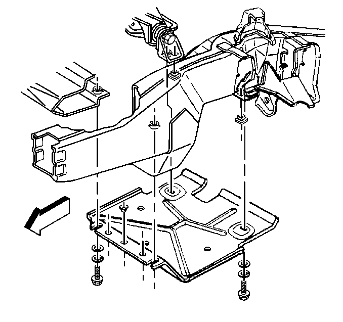
- Remove the differential carrier shield mounting bolts.
- Remove the differential carrier shield.
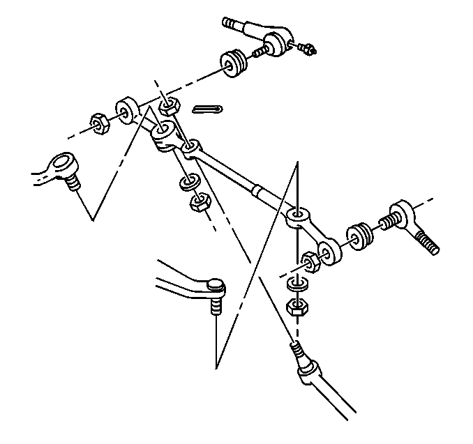
- Remove inner tie rods ball stud nuts.
- Remove the inner tie rods ball studs from the relay rod using J 6627-A .
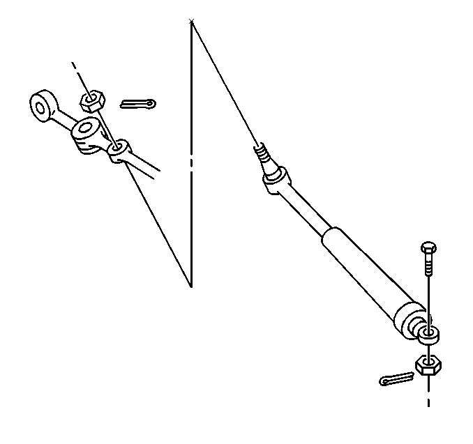
- Remove the steering shock absorber ball stud nut at the relay rod.
- Disconnect the steering shock absorber from the relay rod usingJ 24319-B .
- Remove the pitman arm ball stud nut at the relay rod.
- Disconnect the pitman arm ball stud from the relay rod using J 24319-B .
- Remove the idler arm ball stud nut at the relay rod.
- Disconnect the idler arm ball stud from the relay rod using J 24319-B .
- Remove the relay rod.
- Inspect the following components:
- Clean the threads on the ball stud and ball stud nut.
Important: Use the proper tool in order to separate all ball joints.


| • | The threads on the tie rod for damage |
| • | The threads on the tie rod end for damage |
| • | The ball stud threads for damage |
| • | The ball stud seals for excessive wear |
Installation Procedure
- Install the idler arm ball stud to the relay rod.
- Install the new nut to the idler arm ball stud at the relay rod.
- Install the relay rod ball stud to the pitman arm.
- Install the new nut to the pitman arm ball stud at the relay rod.
- Connect the steering shock absorber to the relay rod.
- Install the steering shock absorber ball stud nut at the relay rod.
- Install the inner tie rod ball studs to the relay rod.
- Install the new nuts to the inner tie rod ball studs at the relay rod.
- Install the differential carrier shield.
- Install the differential carrier shield mounting bolts.
- Install the steering linkage shield. Refer to Steering Linkage Shield Replacement .
- Lower the vehicle.
- Adjust the front toe. Refer to Front Toe Adjustment in Wheel Alignment.

Ensure that the seal is on the stud.
Notice: Use the correct fastener in the correct location. Replacement fasteners must be the correct part number for that application. Fasteners requiring replacement or fasteners requiring the use of thread locking compound or sealant are identified in the service procedure. Do not use paints, lubricants, or corrosion inhibitors on fasteners or fastener joint surfaces unless specified. These coatings affect fastener torque and joint clamping force and may damage the fastener. Use the correct tightening sequence and specifications when installing fasteners in order to avoid damage to parts and systems.
Tighten
Tighten the idler arm ball stud nut to 82 N·m (60 lb ft).
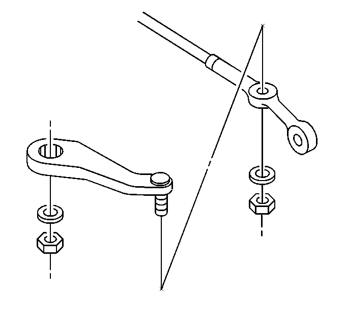
Ensure that the seal is on the stud.
Tighten
Tighten the pitman arm ball stud nut to 83 N·m (61 lb ft).

Tighten
Tighten the steering shock absorber ball stud nut to 63 N·m (46 lb ft).

Ensure the seal is on the stud.
Tighten
Tighten the inner tie rod ball stud nuts to 47 N·m (35 lb ft).

Tighten
Tighten the differential carrier shield mounting bolts to 25 N·m
(19 lb ft).
