For 1990-2009 cars only
| Figure 1: |
Power And Grounding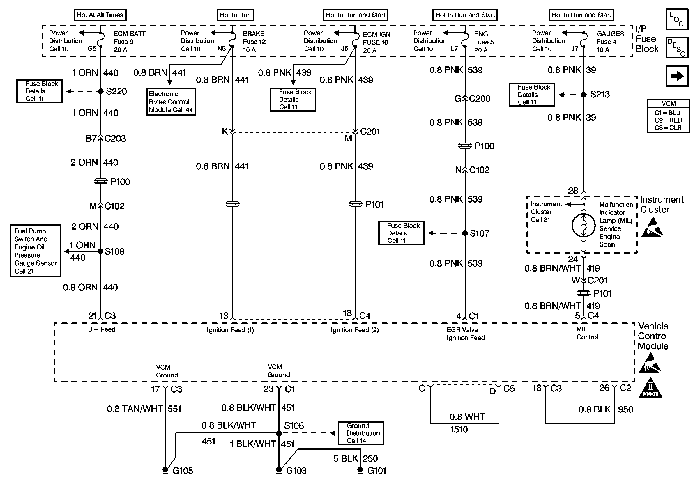
|
| Figure 2: |
Data Link Connector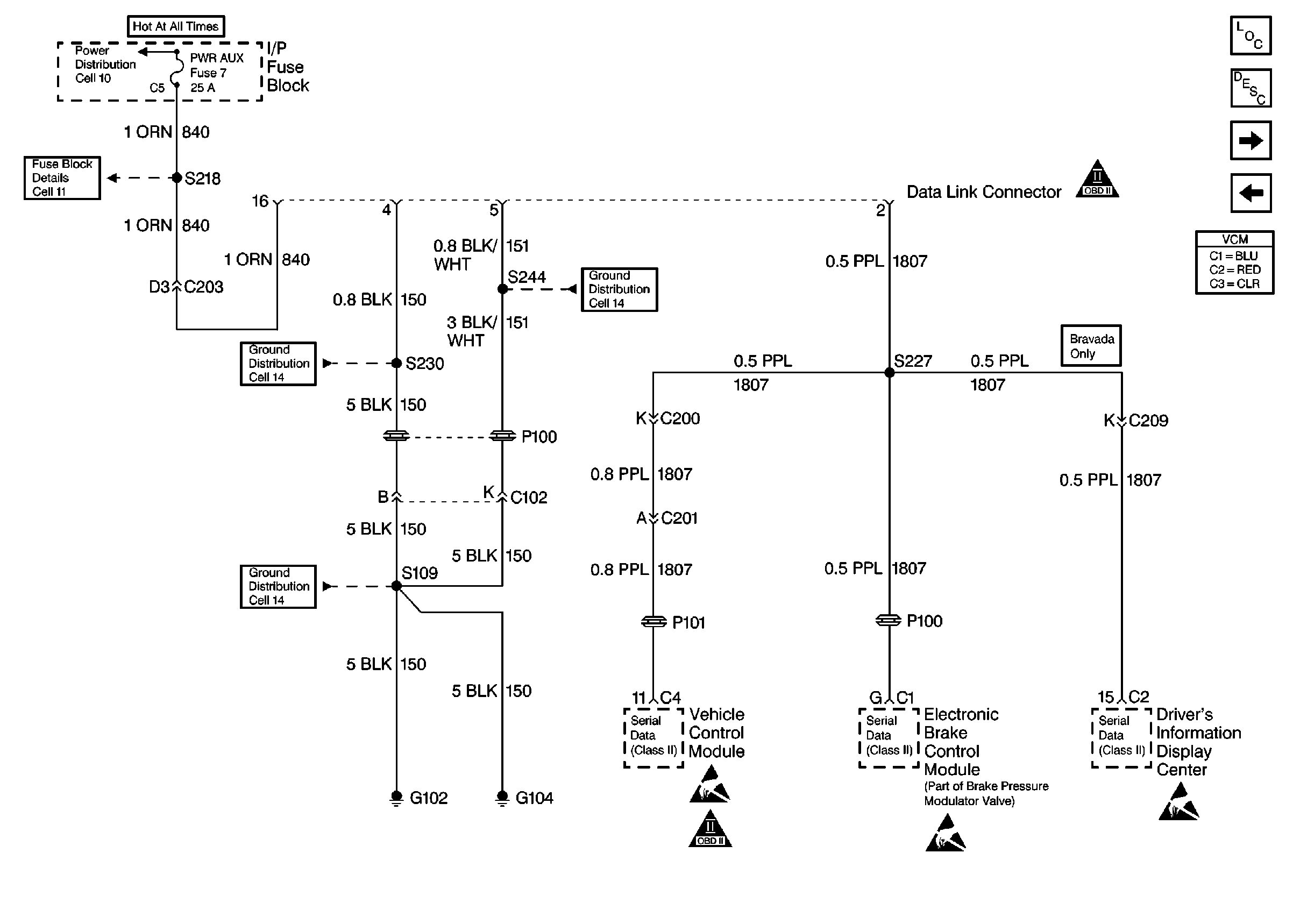
|
| Figure 3: |
Ignition Controls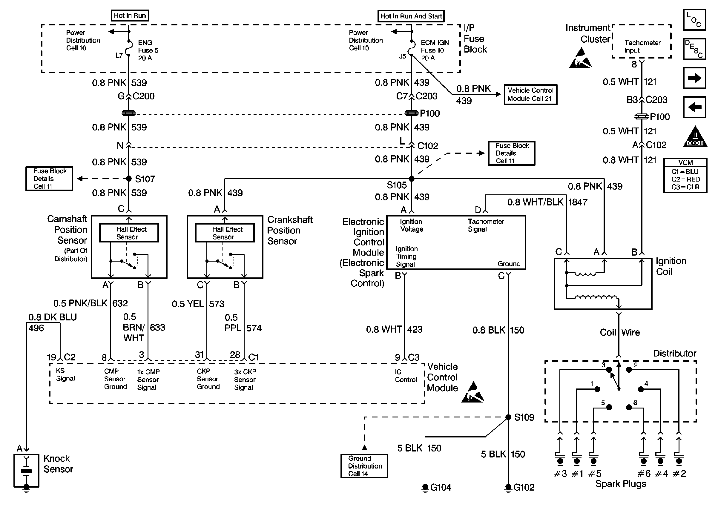
|
| Figure 4: |
Fuel Level Sensor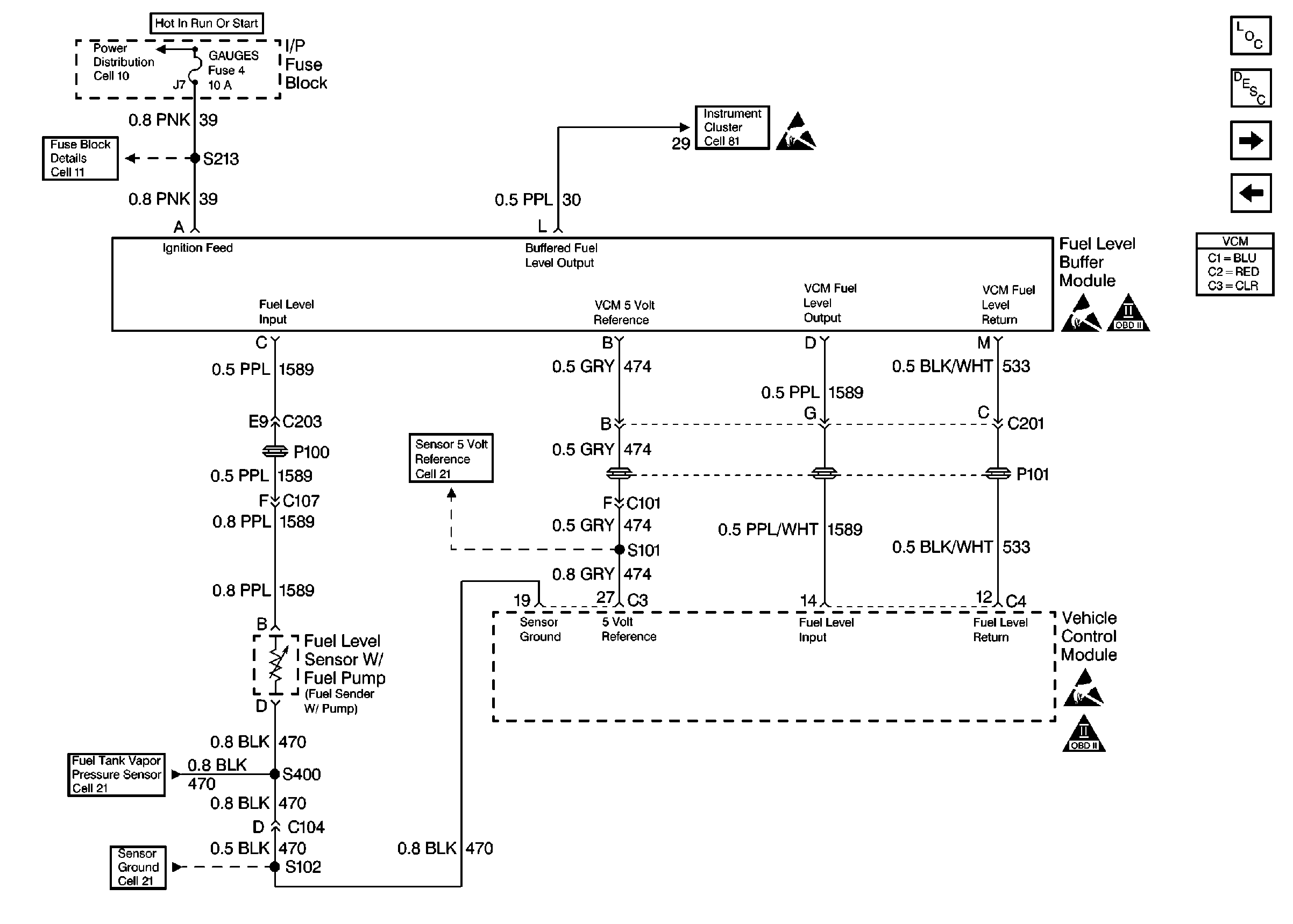
|
| Figure 5: |
Fuel Pump Controls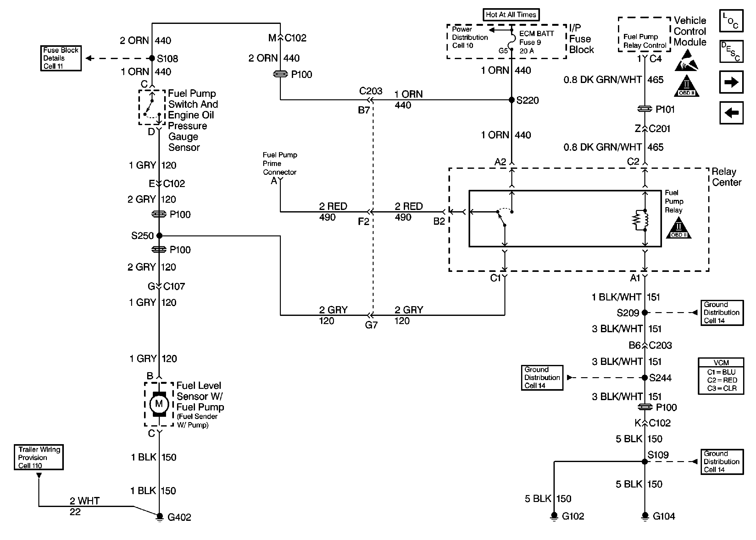
|
| Figure 6: |
Fuel Injector Controls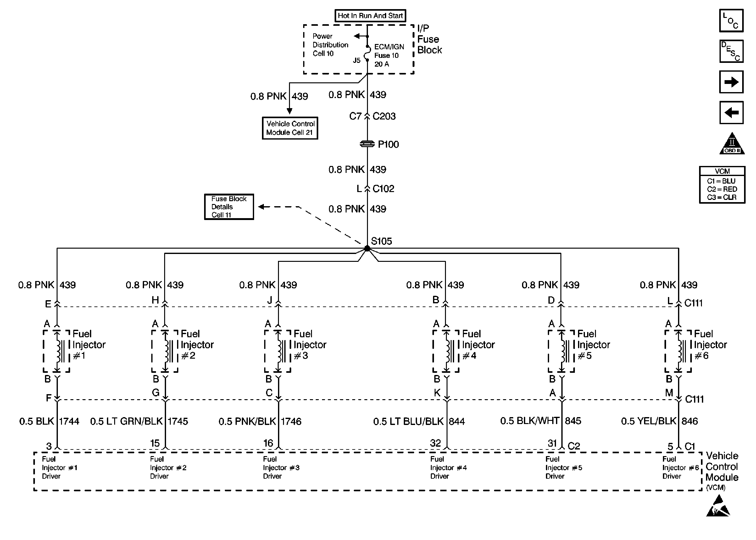
|
| Figure 7: |
Sensors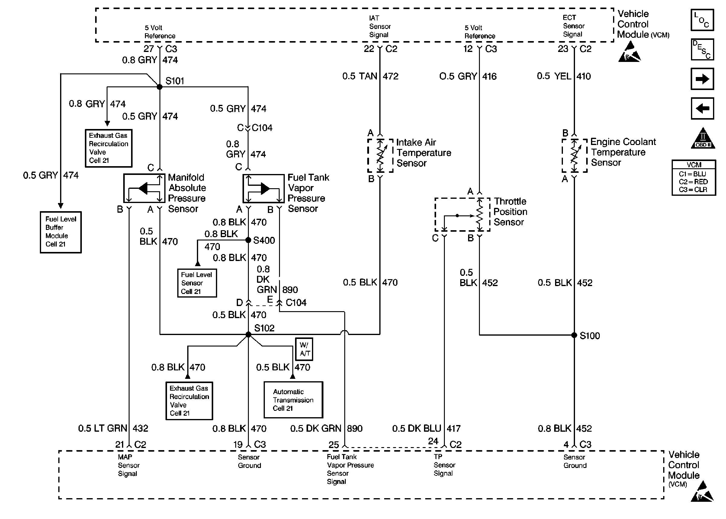
|
| Figure 8: |
Valve Controls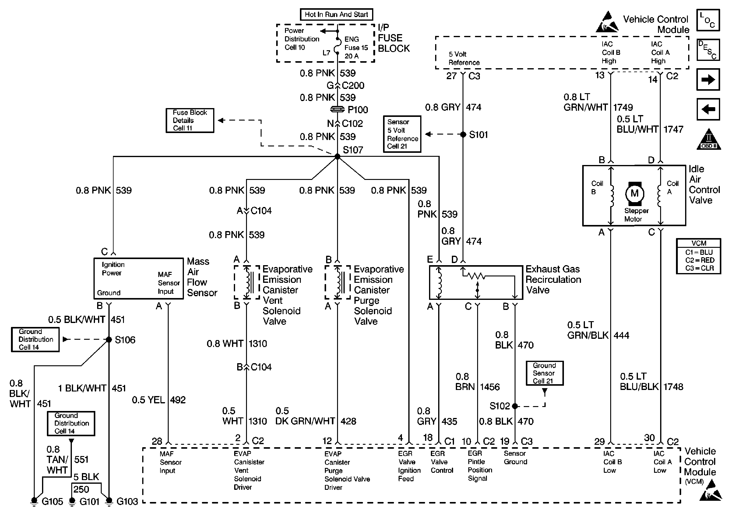
|
| Figure 9: |
Oxygen Sensors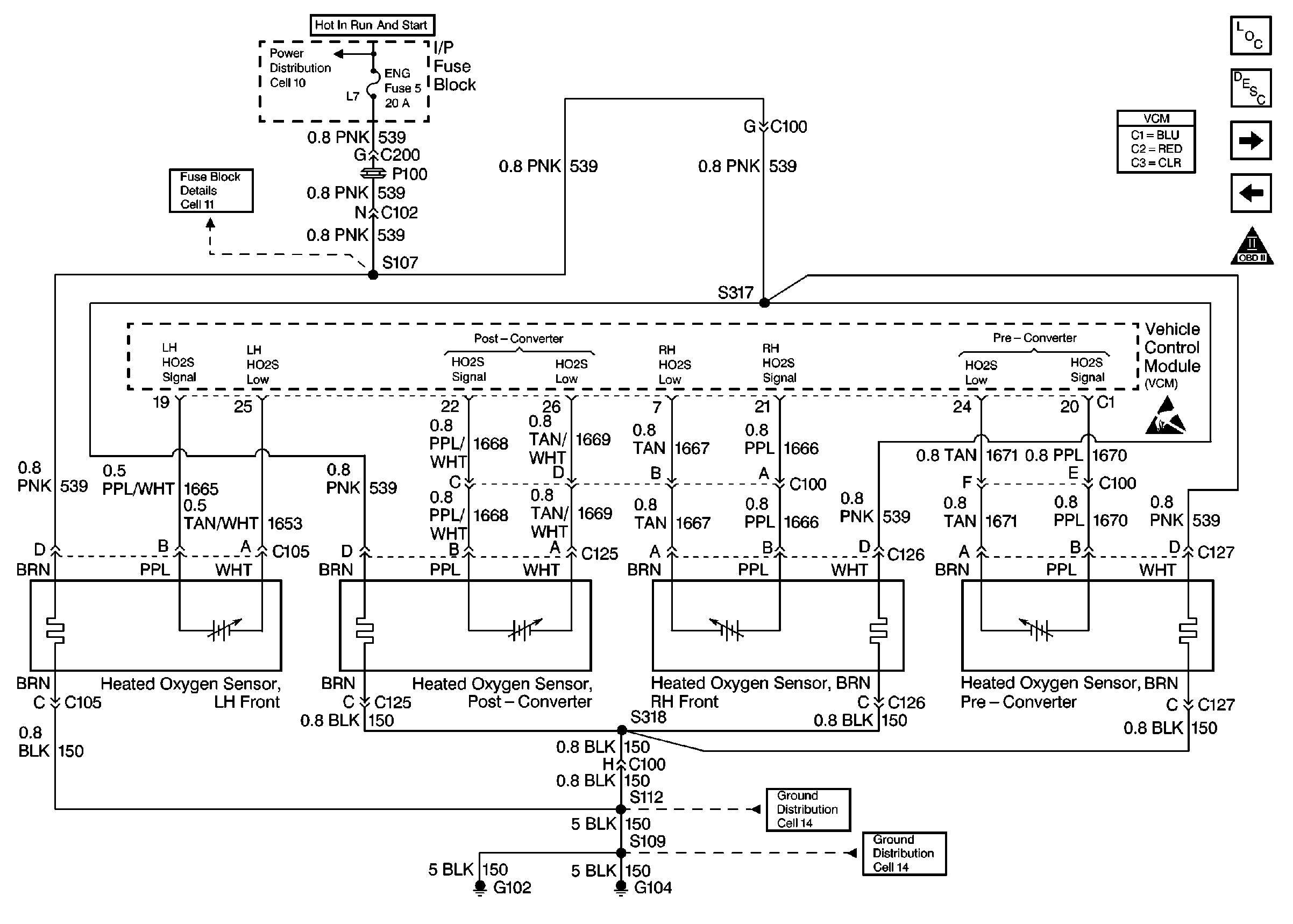
|
| Figure 10: |
Manual Transmission Inputs And Outputs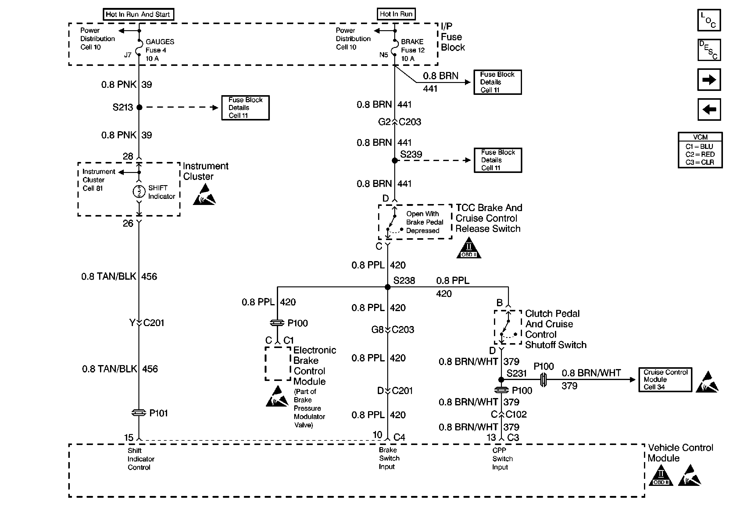
|
| Figure 11: |
Four Wheel Drive Inputs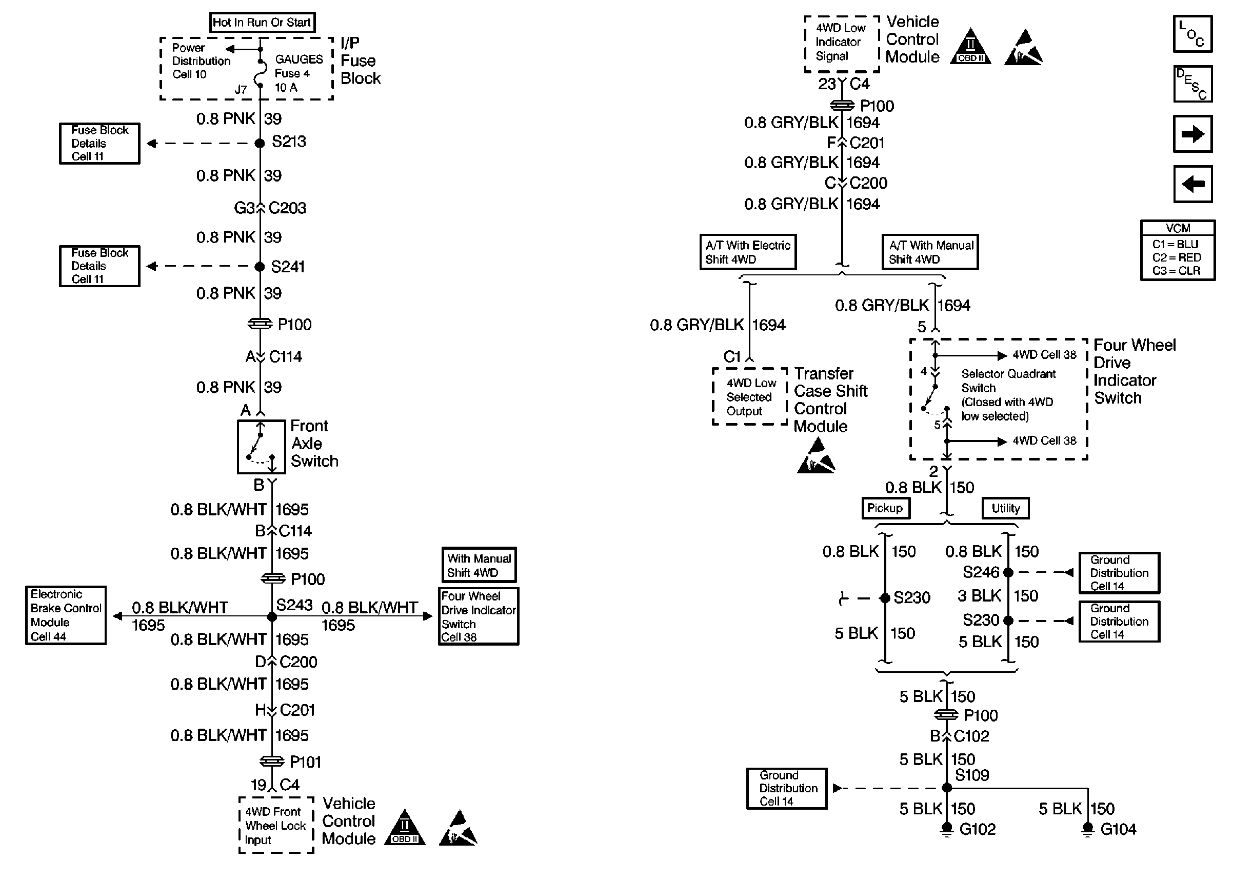
|
| Figure 12: |
Speed Sensors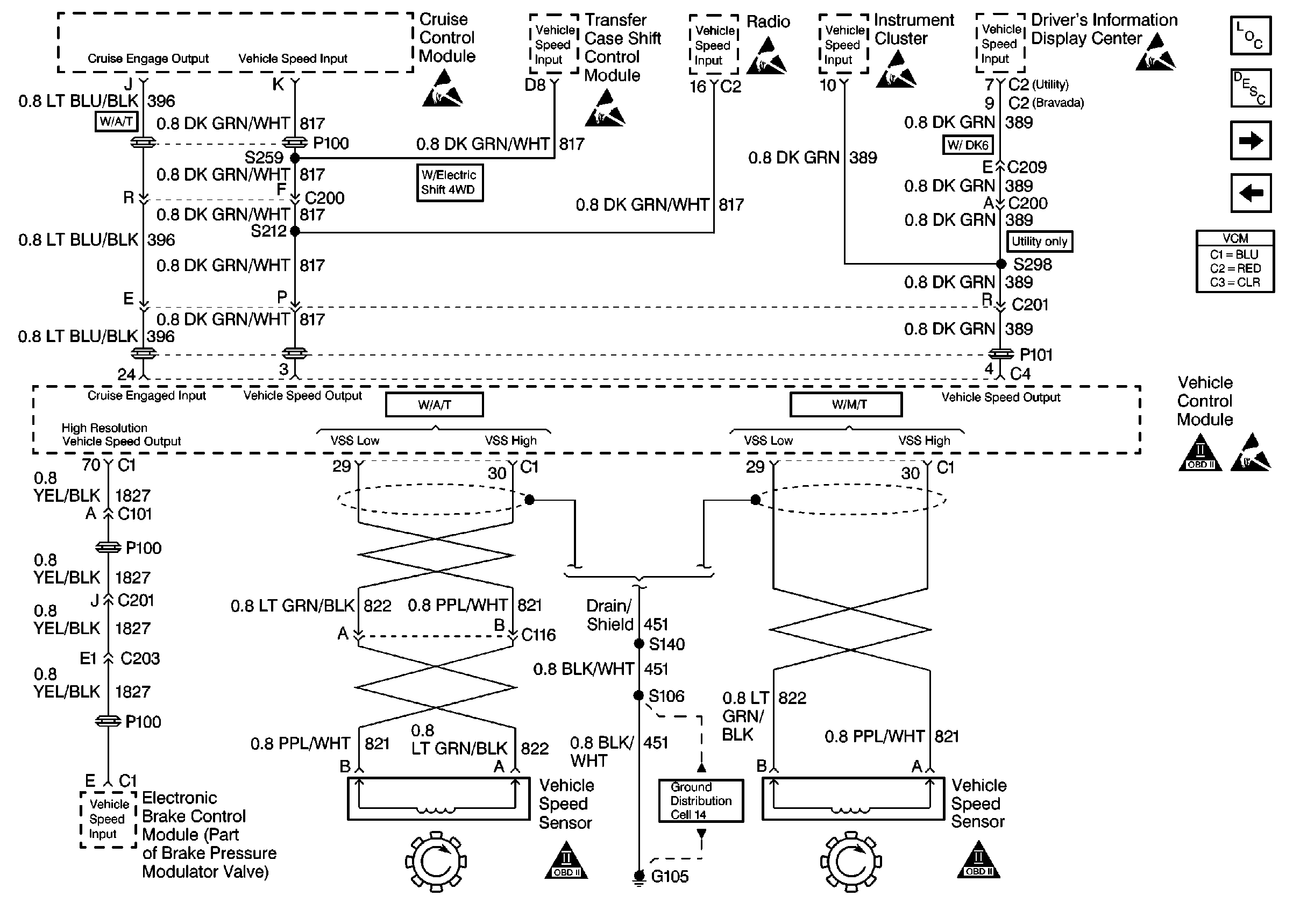
|
| Figure 13: |
Automatic Transmission Shift Solenoid Control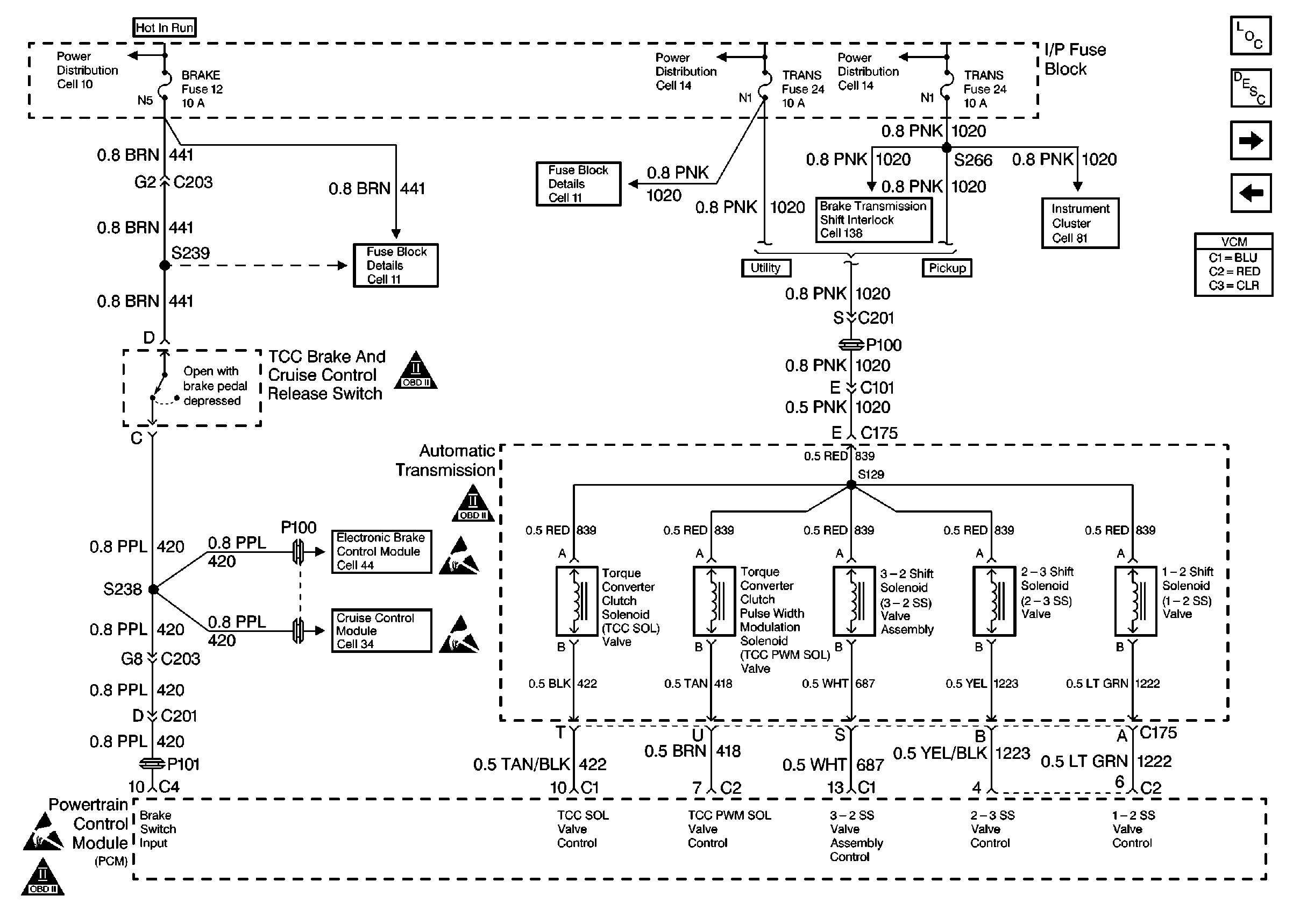
|
| Figure 14: |
Automatic Transmission Range Inputs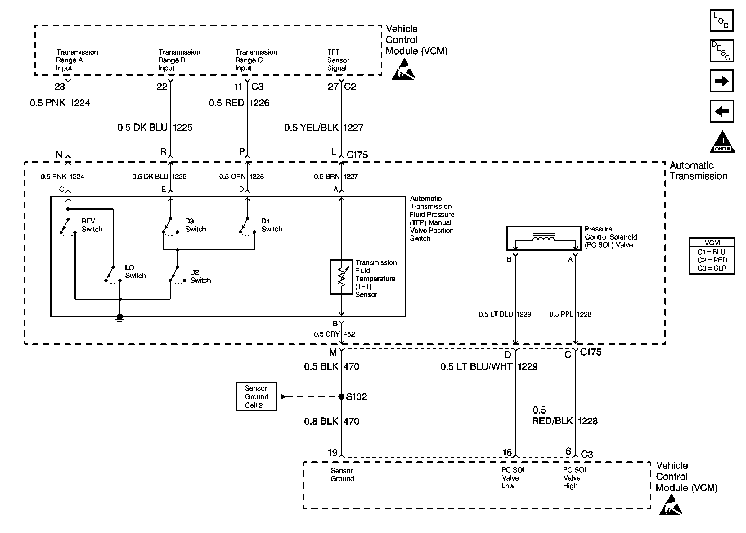
|
| Figure 15: |
AC Controls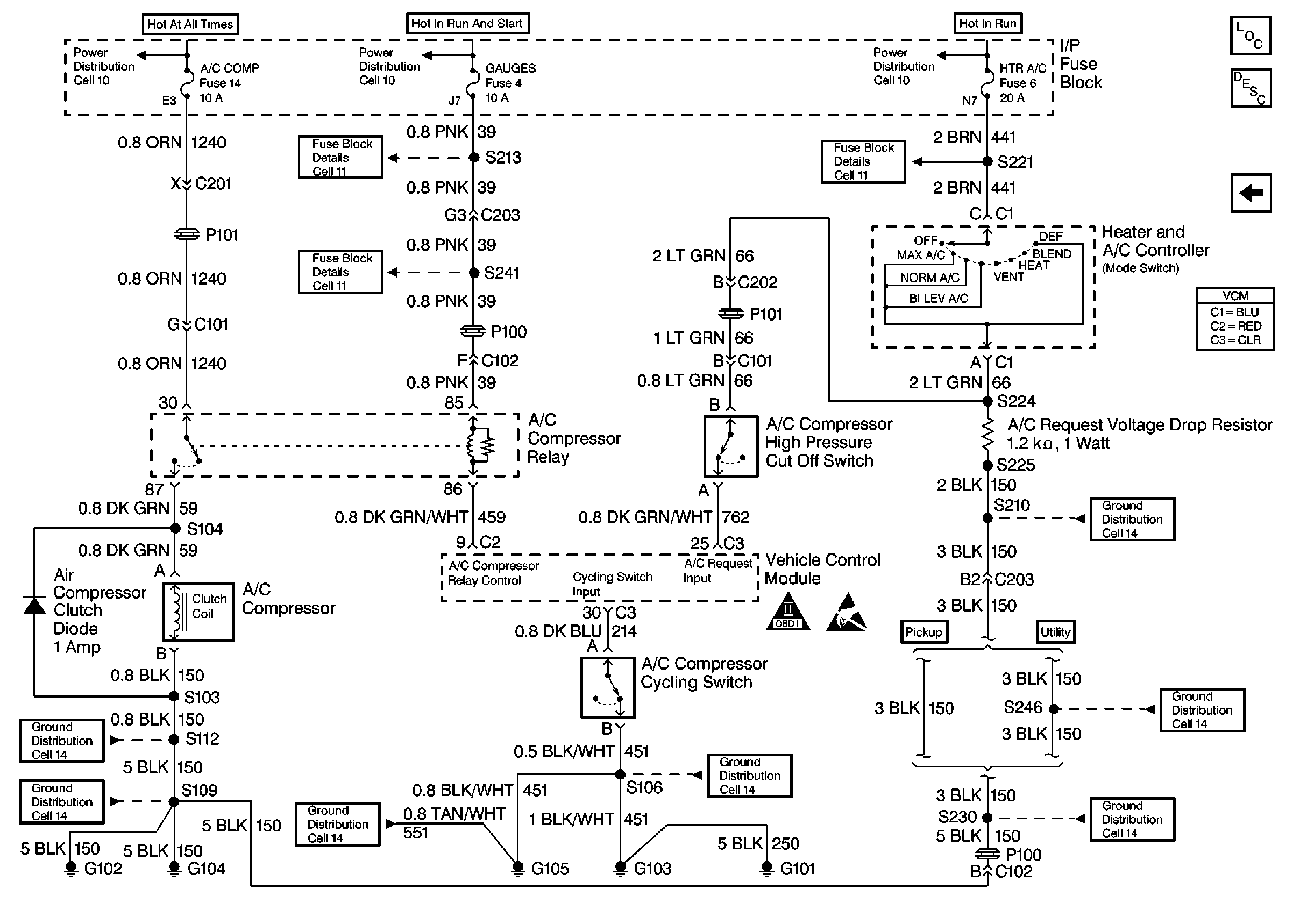
|
