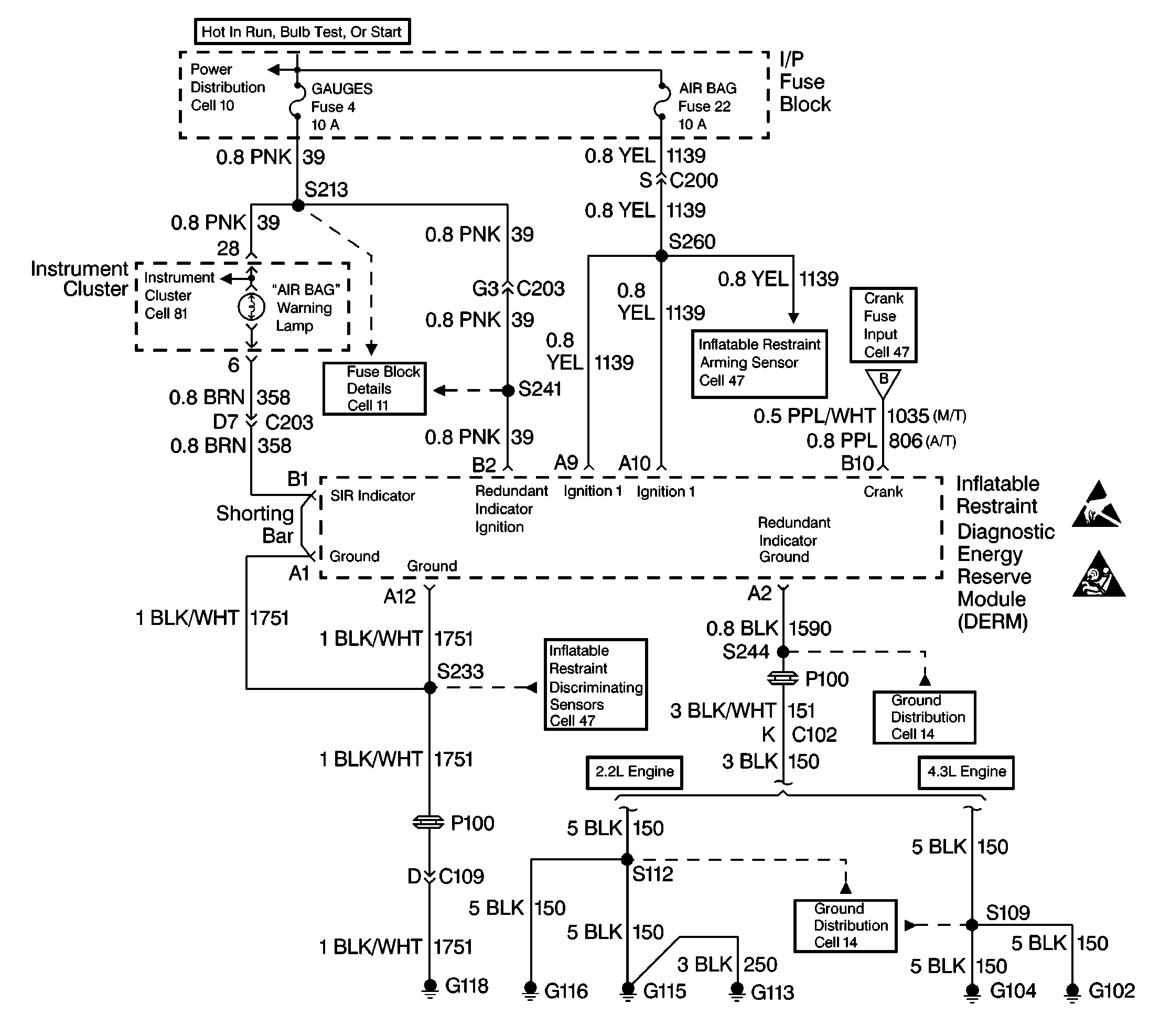
Circuit Description
When the ignition switch is turned ON, battery voltage is applied to the AIR BAG warning lamp. Battery voltage is also applied to the Ignition 1 input terminal A9 and the Ignition 1 input terminal A10. The inflatable restraint Diagnostic Energy Reserve Module (DERM) responds by flashing the AIR BAG warning lamp seven times. The flashing alternates between the primary lamp driver and the redundant lamp driver. The DERM monitors the redundant lamp driver output by comparing the output state at the SIR Indicator terminal B1 to the microprocessor commanded state. When the ignition 1 is above a specified value and the output state does not match the commanded state of the redundant lamp driver for 400 milliseconds, DTC B1062 is set.
Conditions for Setting the DTC
The Ignition 1 voltage is above a specified value, and the output state at the SIR Indicator terminal B1 does not match the commanded state of the redundant lamp driver for 400 milliseconds, during Continuous monitoring tests.
Action Taken When the DTC Sets
The DERM attempts to turn on the AIR BAG warning lamp using the primary lamp driver and the DERM sets a diagnostic trouble code.
Conditions for Clearing the DTC
The ignition switch is turned OFF.
Diagnostic Aids
An intermittent condition may be caused by one of the following reasons:
| • | A poor connection to the DERM at terminal A2 |
| • | A poor connection to the DERM at terminal B2 |
| • | An open in CKT 1851 |
| • | An open in CKT 39 |
Test Description
Refer to step numbers on the diagnostic table.
-
Start at the SIR Diagnostic System Check for all diagnosis.
-
This test checks for an open in the Redundant Indicator ground circuit.
-
This test checks for an open in the Redundant Indicator Ignition 1 circuit.
-
This test locates the open in the Redundant Indicator Ignition 1 circuit.
When measurements are requested in this table, use J 39200 Digital Multimeter with correct terminal adapter from J 35616 Connector Test Adapter Kit. When a check for proper connection is requested, refer to Intermittents and Poor Connections in Section 8A4. When a wire, connector or terminal repair is requested, use J-38125 Terminal Repair Kit and refer to Wiring Repair.
Step | Action | Value | Yes | No |
|---|---|---|---|---|
Was the SIR Diagnostic System Check performed? | -- | |||
2 | Is DTC B1061 also set? | -- | ||
3 |
Is the DERM electrical harness connector damaged or corroded? | -- | ||
4 | Repair the DERM electrical harness. Has the connector been repaired? | -- | -- | |
5 | Check for proper connection to the DERM at terminals A2 and B2. Are the DERM terminals damaged or corroded? | -- | ||
6 | Check for proper connection to the DERM at terminals A2 and B2. Are the DERM terminals damaged or corroded? | -- | ||
7 | Replace the DERM. Refer to Inflatable Restraint Diagnostic Energy Reserve Module . Has the DERM been replaced? | -- | -- | |
Measure the resistance from the DERM electrical harness connector terminal A2 (ground) to A12 (ground). Is the resistance less than the value specified? | 5 ohms | |||
9 | Repair the open in circuit 1851. Has the open circuit been repaired? | -- | -- | |
Is the value specified? | 1 V | Go to Integrity Check | ||
11 |
Is connector C203 damaged or corroded? | -- | ||
12 | Repair the connector C203. Has the connector been repaired? | -- | -- | |
Is the voltage less than the value specified? | 1 V | |||
14 |
Has the open circuit been repaired? | -- | -- | |
15 |
Has the open circuit been repaired? | -- | -- | |
16 |
Have all the SIR system components been reconnected and mounted? | -- | -- | |
17 | Clear the SIR Diagnostic Trouble Codes. Have the SIR Diagnostic Trouble Codes been cleared? | -- | -- |
