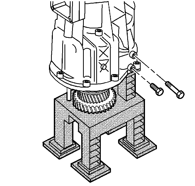
- Remove the two bolts which
attach the idler shaft segment and the idler shaft support collar to the rear
housing.
- Remove the backup lamp switch from the rear housing.
- Remove the electronic speed sensor from the rear housing.
- Remove the shift shaft block-out bushing pin from the front housing.
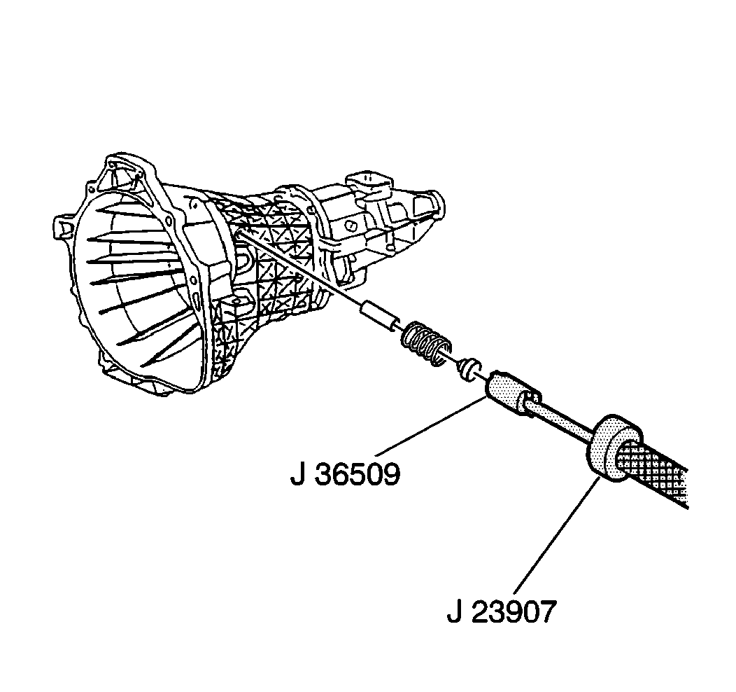
- Using the J 36509
in the detent plug and the J 23907
remove the following components from
the front housing:
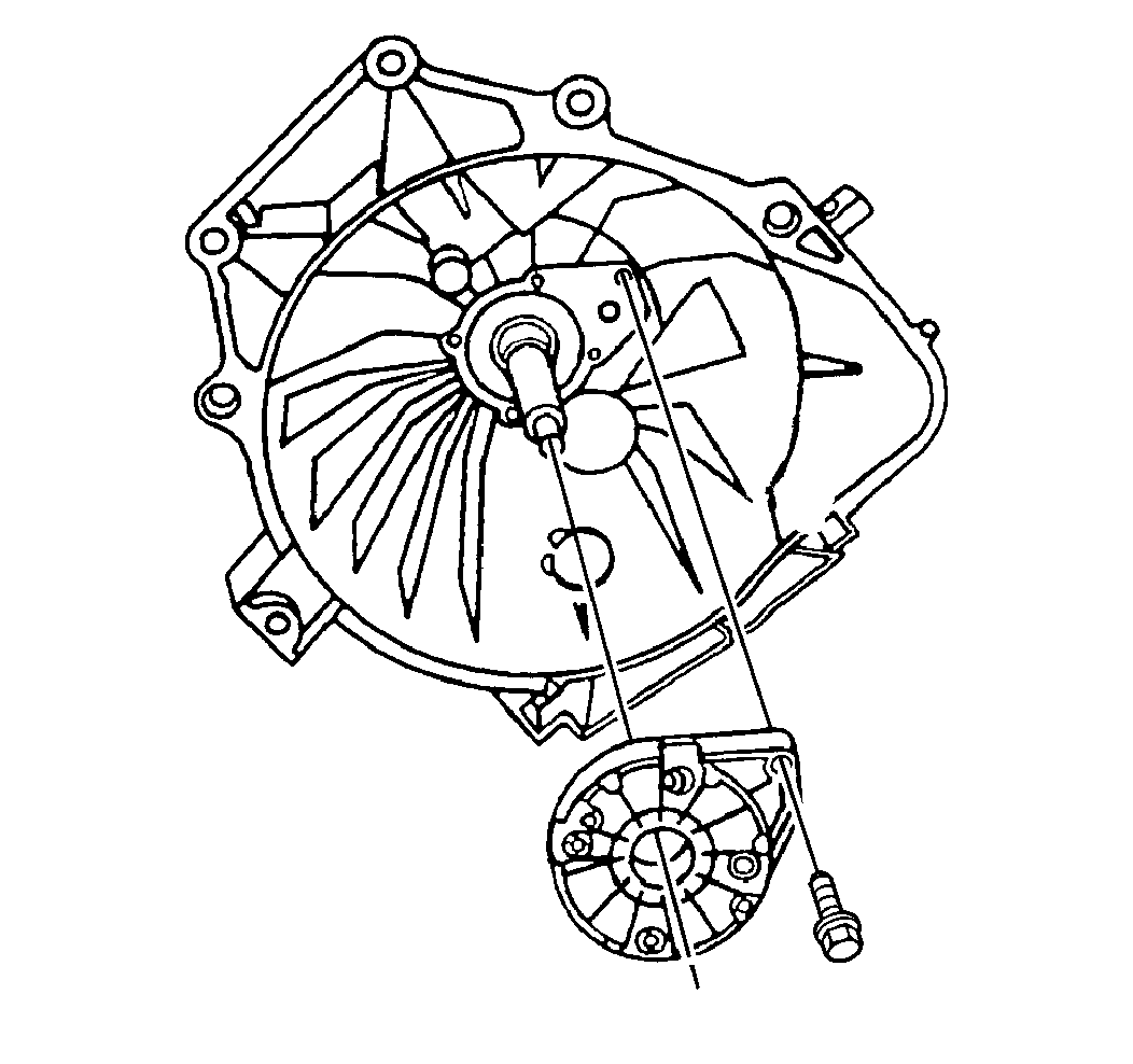
- Remove the five bolts
which secure the input shaft bearing retainer to the front housing.
- Use the J 23907
to remove the input shaft bearing retainer from the front housing.
- Remove the snap ring.
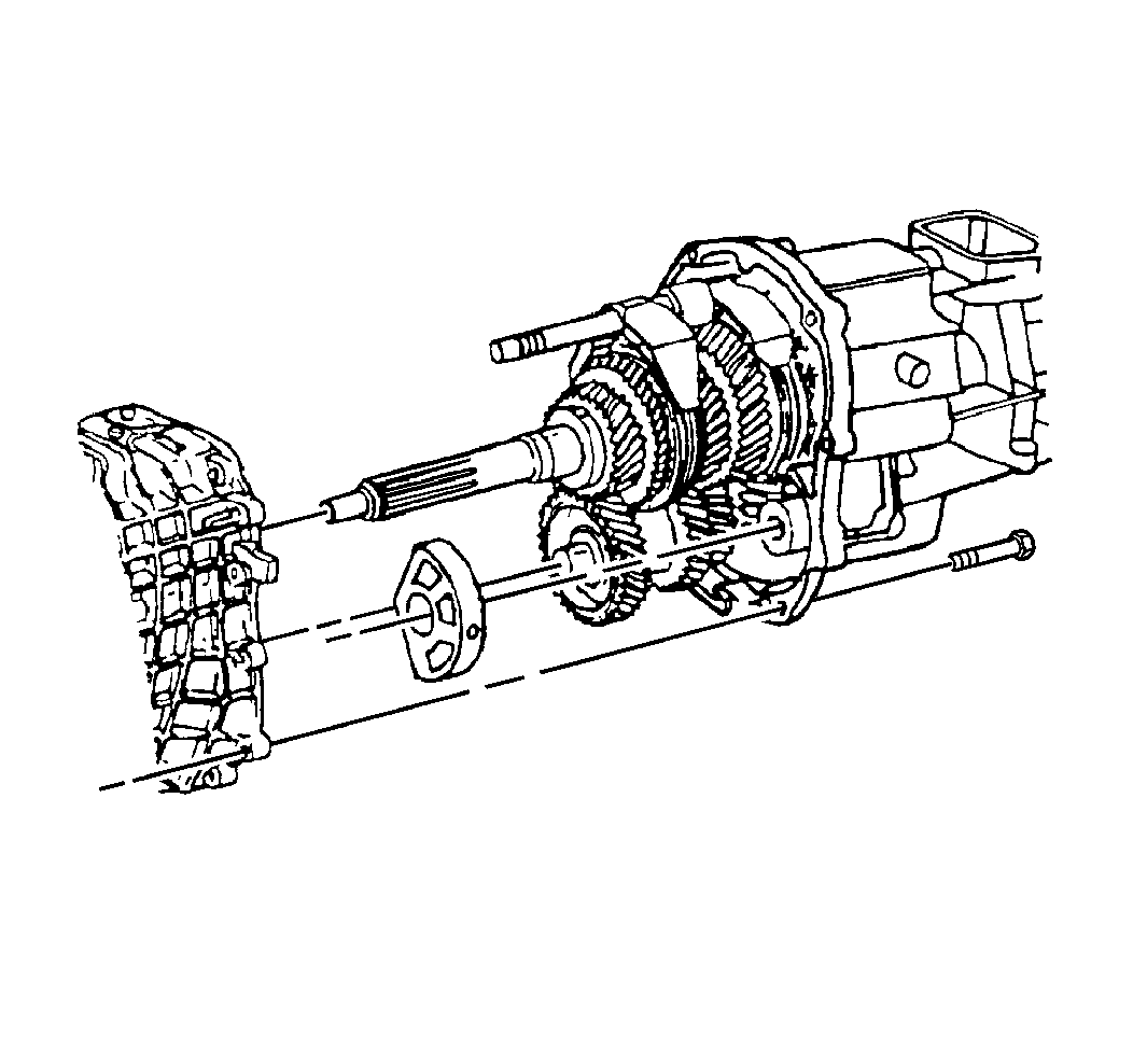
- Remove the nine bolts
securing the front housing to the rear housing.
- Angle the front housing up and press down on the rear housing
in order to separate the front housing from the rear housing.
- Remove the countershaft roller bearing from the countershaft or
the bearing shell.
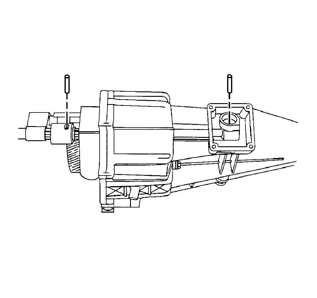
- Remove the shift shaft
lever roll pin from the shift shaft lever:
| • | Rotate the shift shaft lever and the shift shaft bushing. |
| | Important: Do not lose the shift shaft lever plunger or the spring when removing
the shift shaft lever roll pin from the rear housing.
|
| • | Remove the shift shaft lever plunger and the spring. |
| • | Support the shift shaft end while driving out the shift shaft
lever roll pin. |
| • | Allow the roll pin to clear the second gear during removal. |
Important:
| • | Do not bend the shift rail when removing the roll pin. |
| • | Use a 5 mm (3/16 inch) drift punch in order to remove
the roll pin. |
| • | The roll pin will fall into the rear housing. |
- Remove the shift shaft socket roll pin from the bottom of the shift
shaft socket.
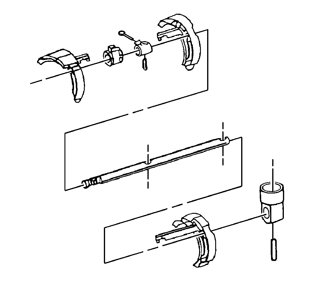
- Remove the following components:
| • | The shift shaft block-out bushing |
- Rotate the third-fourth shift fork counterclockwise.
Remove the third-fourth shift fork.
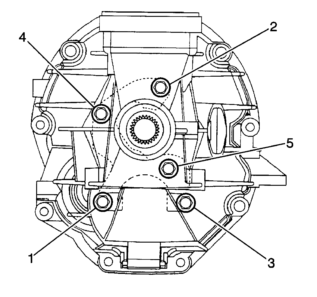
- Remove the bolts (1,2,3,4,5)
securing the output shaft bearing retainer to the center of the rear housing.
- Remove the rear housing from the gear assemblies.
- Remove the reverse idler gear assembly.
- Remove the output shaft bearing retainer.
- Remove the shift forks.
- Remove the countershaft.
- Remove the countershaft bearing snap ring.
- Remove the countershaft bearing.
The countershaft bearing must be pressed off the counter shaft.
- Remove the fifth counter gear from the counter shaft.
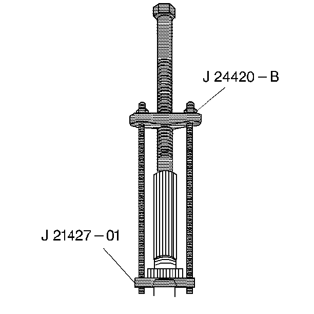
- Use the J 21427-A
and the J 24420-C
in order to remove the speed sensor rotor from the output
shaft.
- Remove the snap ring from the output shaft.
- Use the J 21427-A
and the J 24420-C
in order to remove the output shaft bearing from the output shaft.
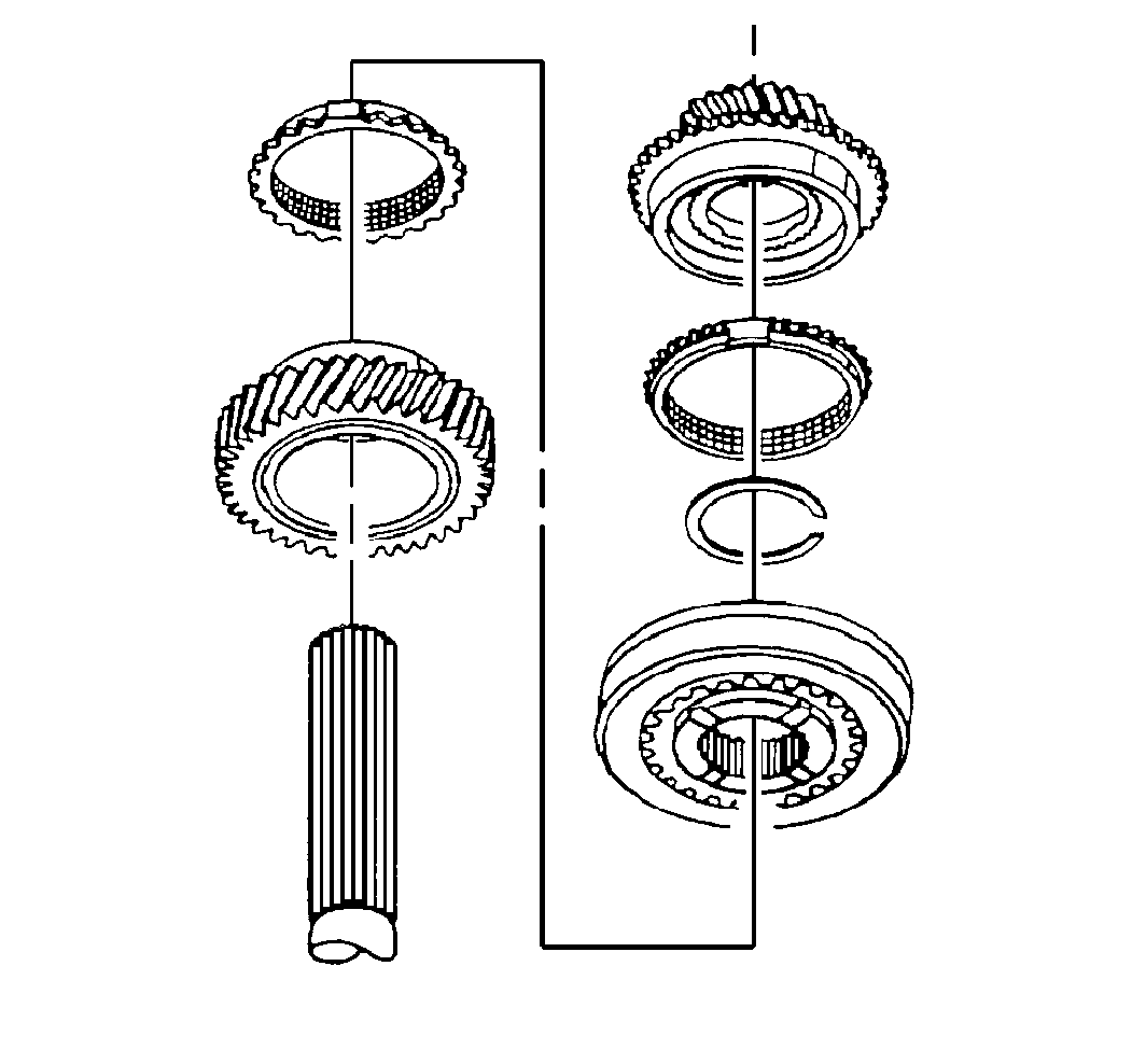
Important: When removing the fifth reverse synchronizer from the main shaft, do
not let the synchronizer retaining rings slide away from the sides of the
fifth-reverse synchronizer assembly. If the synchronizer retaining
rings are moved, the springs, detent balls and ball retainers will
pop out of the synchronizer.
Important: The first and fifth gear blocking rings look the same, but are not interchangeable
with the reverse blocker ring. Prior to removing the reverse gear blocking
ring from the main shaft, mark the reverse gear blocking ring for
installation identification.
- Remove the following components from the output end of the main shaft:
| 28.3. | The synchronizer blocking ring |
| 28.4. | The fifth reverse synchronizer |
| 28.5. | The synchronizer blocking ring |
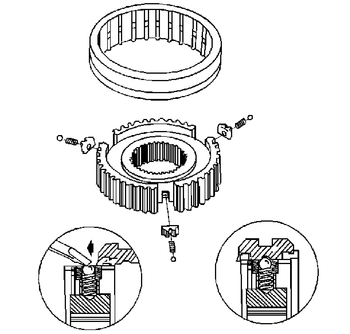
- If the fifth reverse synchronizer
was disassembled, assemble the synchronizer as shown.
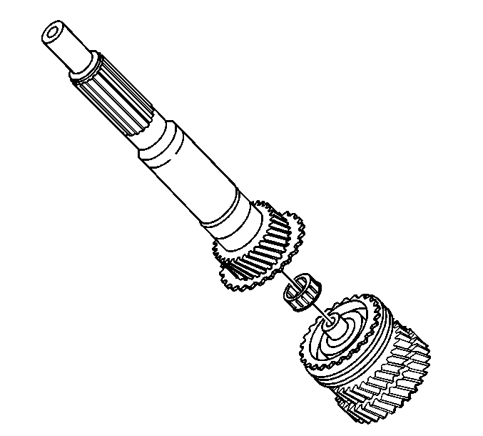
- Remove the input shaft
and the pocket bearing from the input end of the main shaft.
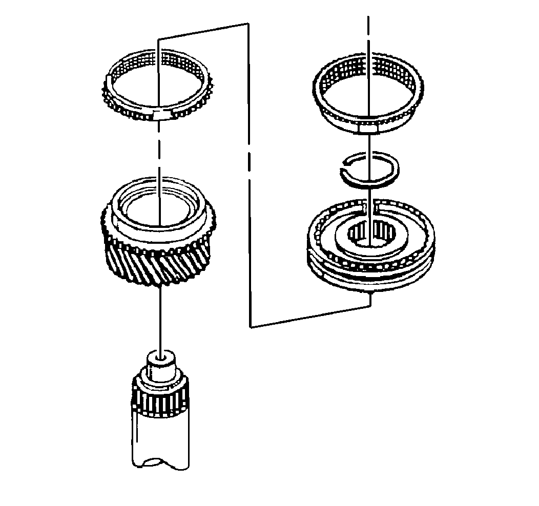
- Remove the snap ring.
- Use a hydraulic press in order to remove the following components
from the main shaft:
| • | The third-fourth gear synchronizer blocking ring |
| • | The third-fourth gear synchronizer |
| • | The third-fourth gear synchronizer blocking ring |
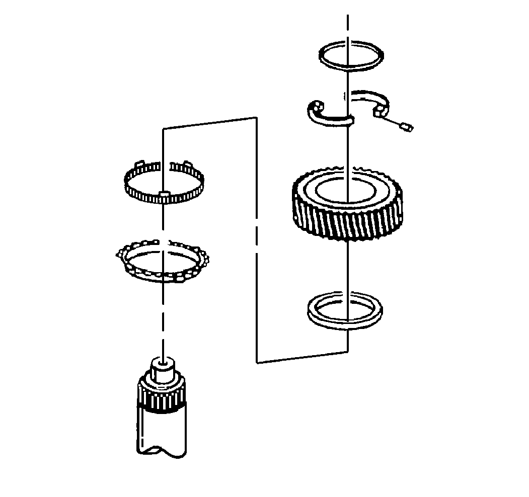
- Remove the following components
from the main shaft:
| • | The two piece split washer, pin, and retaining ring |
| • | The second gear synchronizer blocking ring. |

- Use J 21427-A
and J 24420-C
to remove the second gear from the main shaft.
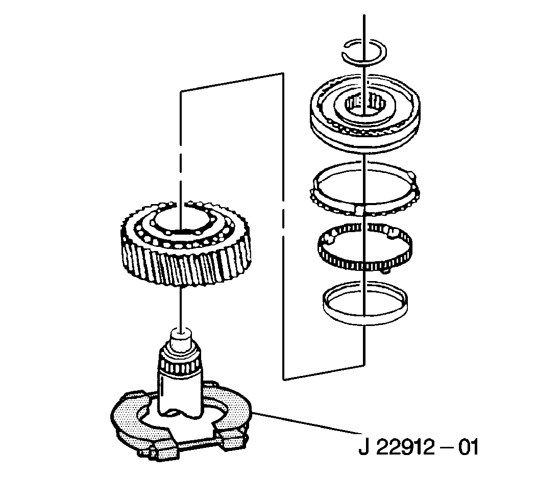
Important: When removing the fifth reverse synchronizer from the main shaft, do
not let the synchronizer retaining rings slide away from the sides of the
fifth-reverse synchronizer assembly. If the synchronizer
retaining rings are moved, the springs, detent balls and
ball retainers will pop out of the synchronizer.
Important: Scribe the synchronizer hub to the output shaft prior to disassembly.
- Use the J 22912-01
and
a hydraulic press to remove the following components from the
main shaft:
| • | The first and second gear synchronizer assembly |
| • | The first gear synchronizer blocking ring |

- If the fifth reverse synchronizer
was disassembled, assemble the synchronizer as shown.
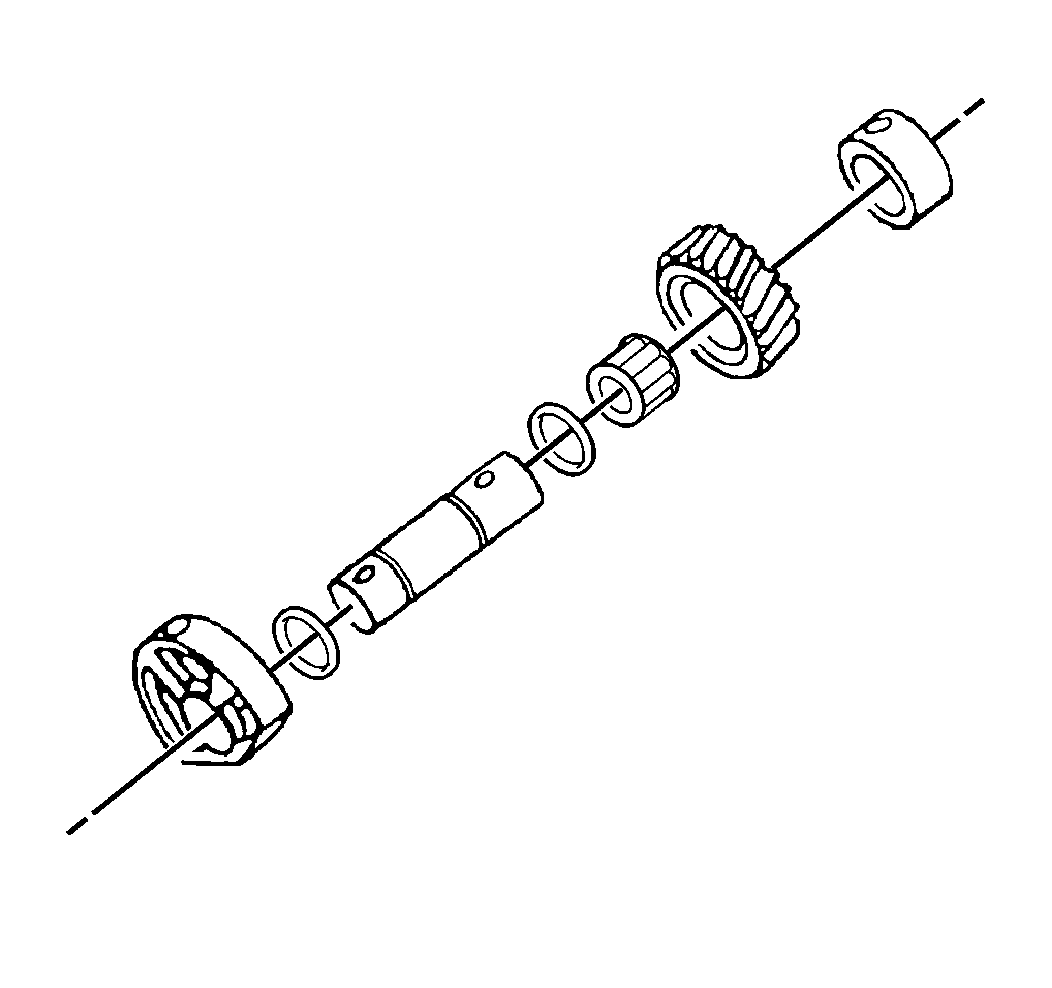
- Remove the following components
from the reverse idler shaft:
| • | The two o-rings from the shaft |
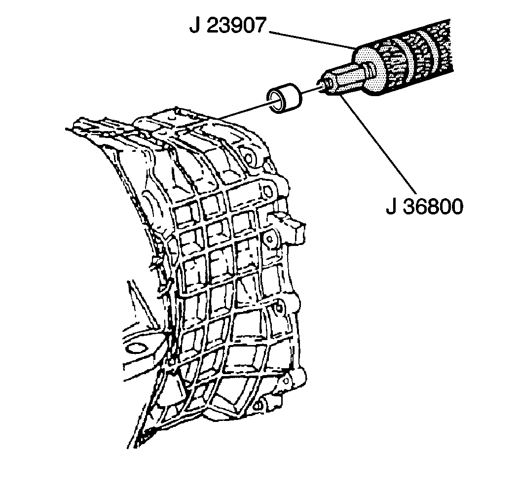
- Use the J 23907
and J 36800
in order to remove the front shift rail bushing from the
front housing.
- Remove the input shaft bearing from the front housing.
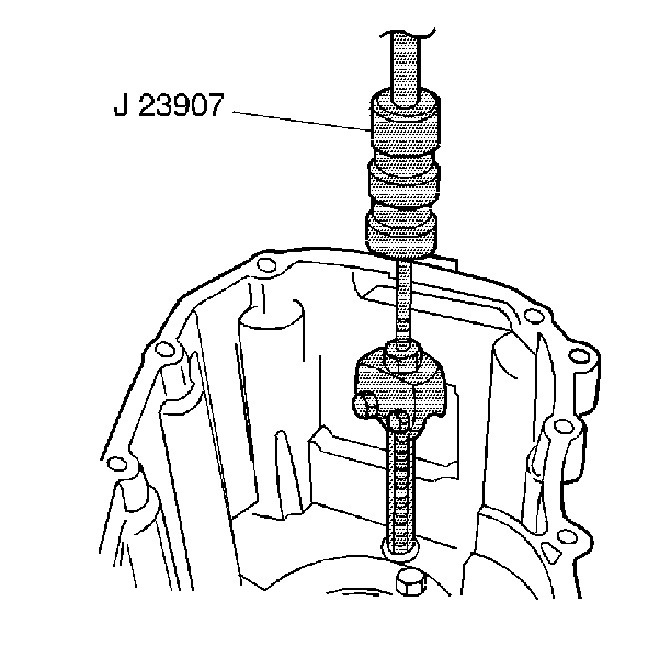
Important: During the removal of the shift shaft rail rear bushing, if the bushing
lip breaks off, position the puller legs behind the inside (outer edge) of
the lip and repeat the removal procedure.
- Use the J 23907
in
order to remove the rear shift rail bushing from the rear housing.
| • | Position the puller legs behind the bearing lip. |
| • | Tighten the puller legs. |
| • | Pull with the slide hammer in order to remover the bushing. |
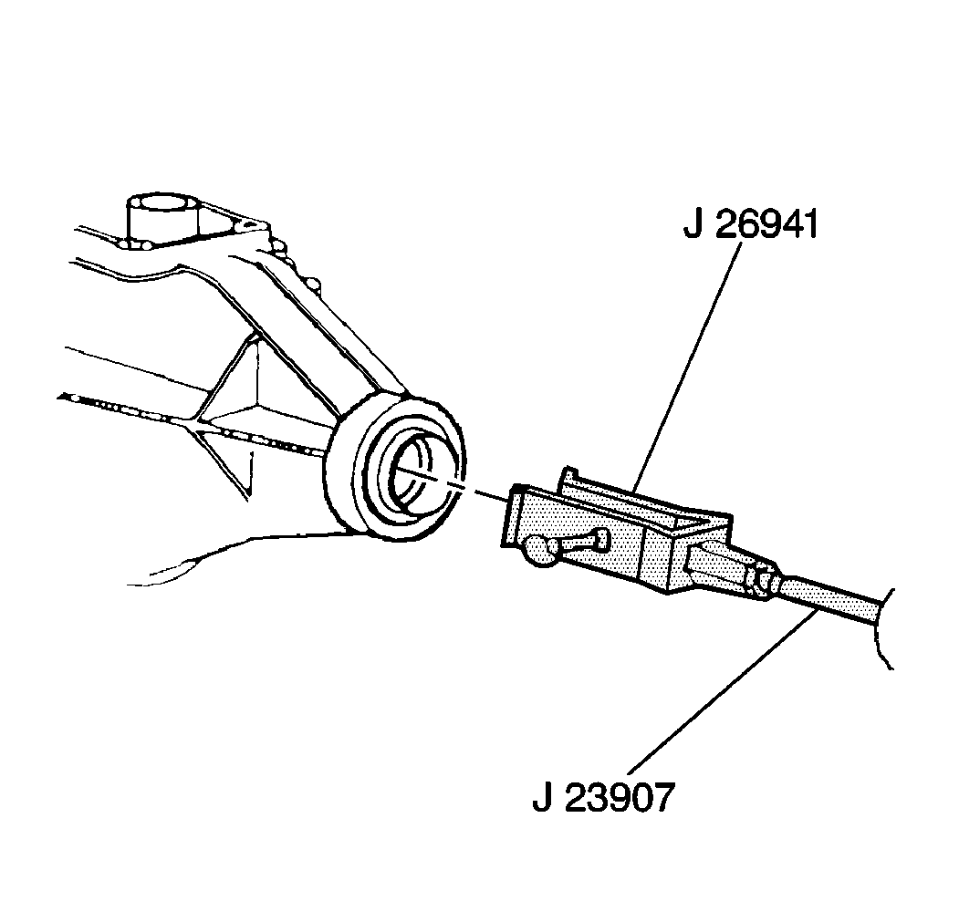
- Use the J 26941
and J 23907
in order to remove the slip yoke oil seal
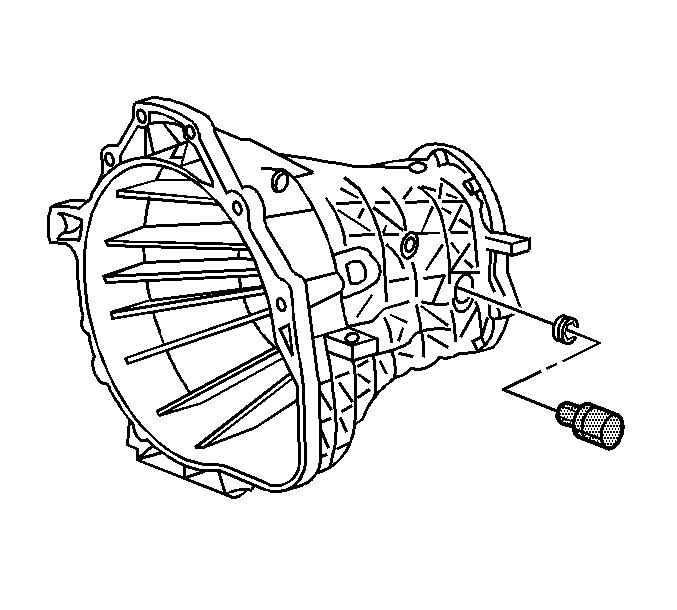
- Use the J 36511
in order to remove the oil fill plug.
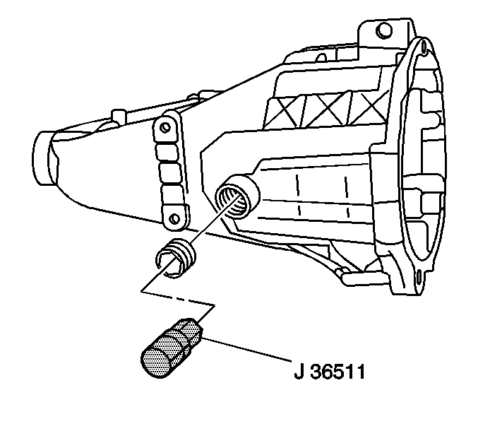
- Use the J 36511
in order to remove the oil drain plug.
- Remove all existing gasket material from the transmission housing.


