Important: When installing the input shaft bearing retainer oil seal, ensure the
lip of the oil seal is installed toward the installing tool J 38801
.
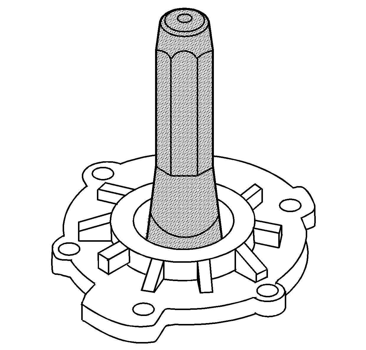
- Using J 38801
, install
the oil seal into the main drive gear bearing retainer.
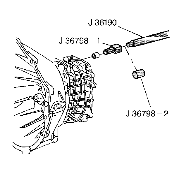
- Using J 36190
and J 36798
,
install the input shaft bearing.
Press the bearing until the snap ring is seated.
- Using J 36511
and J 36507
, install the shift shaft front housing bushings.
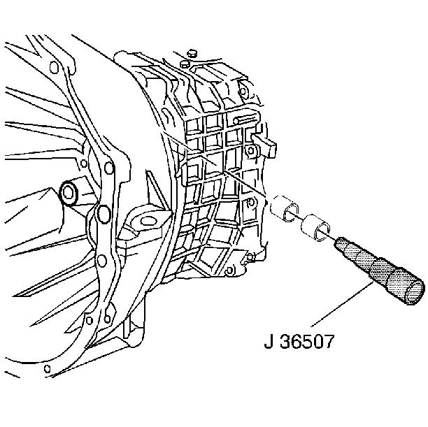
- Using J 36507
, install the two detent plunger bushings.
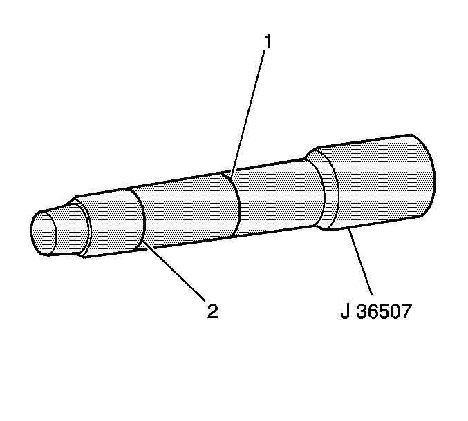
- Install the first bushing to the area where the second scribe mark on
the tool is aligned with the housing.
- Install the second bushing to the area where the first scribe
mark on the tool is aligned with the housing.
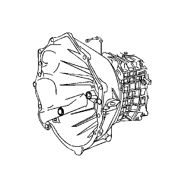
- Install the transmission
vent.
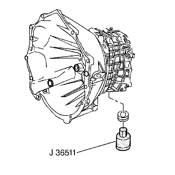
- Using J 36511
install the oil drain plug.
Apply teflon pipe sealant GM P/N 12346004 to the drain
plug threads.
Tighten
Tighten the drain plug to 60 N·m (44 lb ft).
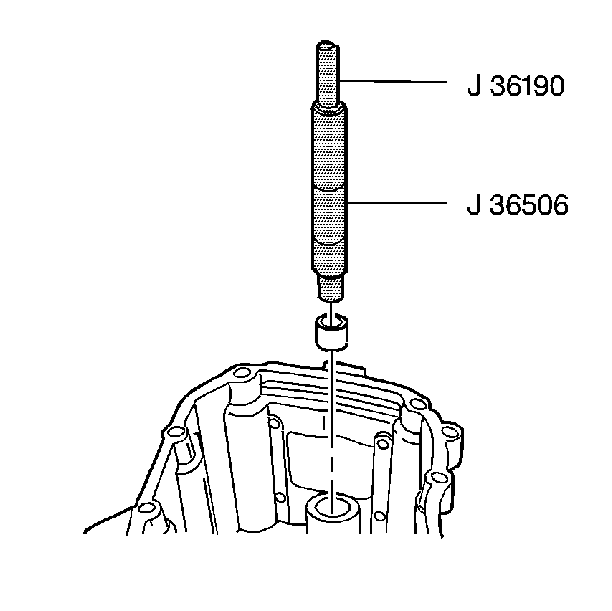
- Using J 36506
and J 36190
, install the rear housing shift shaft bearing.
| 9.1. | The writing on the bearing lip should face down. |
| 9.2. | Install the bearing flush with the housing surface. |
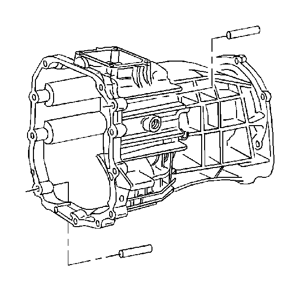
- Install 2 dowel pins in
the housing flange.
Drive the dowel pins rearward and flush with the flange surface.
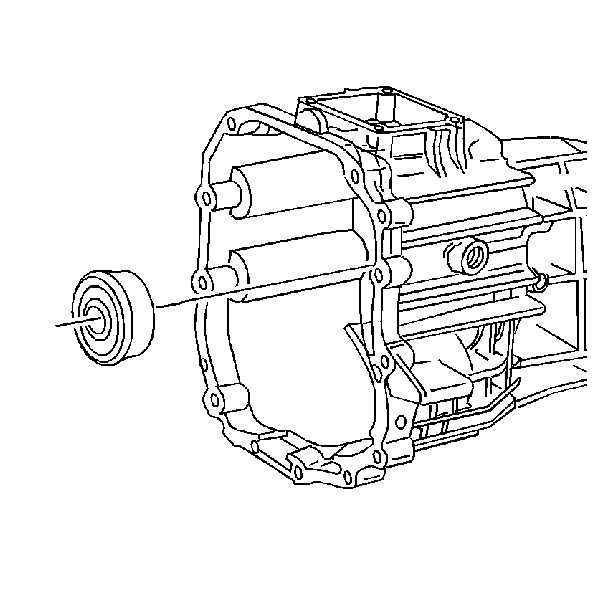
- If 4WD vehicle, install
the main shaft rear bearing in the rear housing.
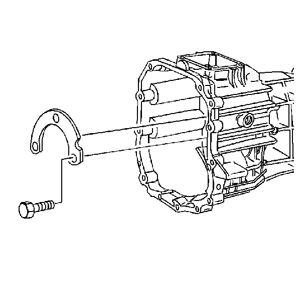
- If 4WD vehicle, install
the main shaft bearing retainer and the bolts.
Tighten
Tighten the main shaft bearing retainer bolts to 22 N·m (16 lb in).
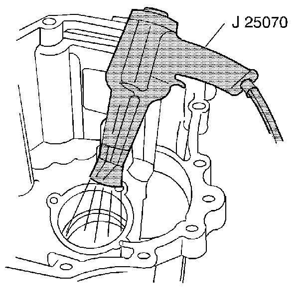
- Using the J 25070
heat the rear housing countershaft bearing
bore for ten minutes.
- Install the countershaft bearing race.
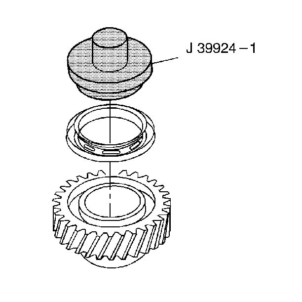
- Using J 39924-1
, install the reverse speed gear
drag seal.
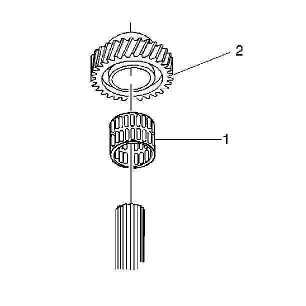
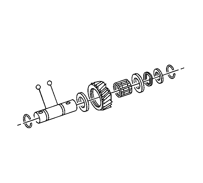
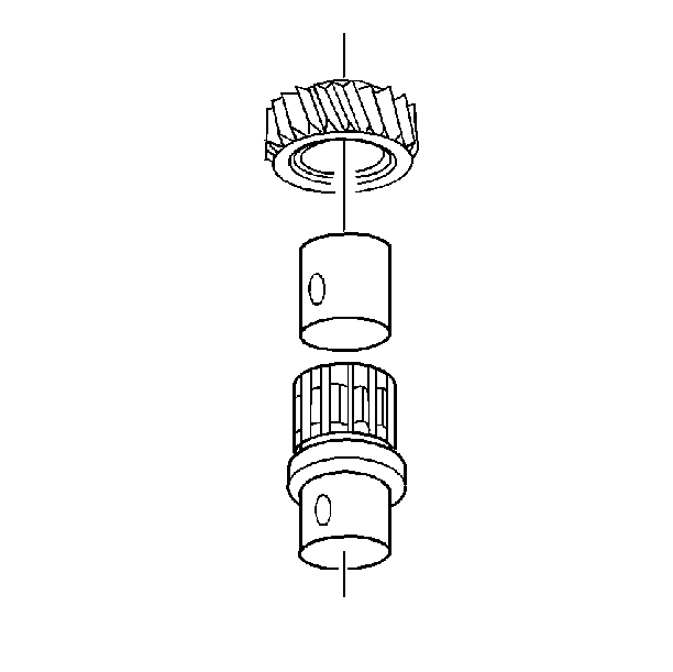
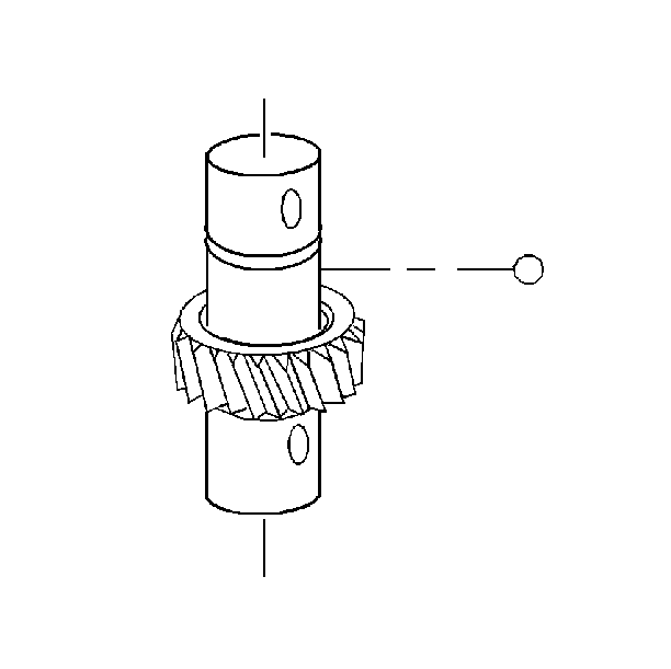
- Install the reverse speed
gear needle bearing (1).
- Install the reverse speed gear (2).
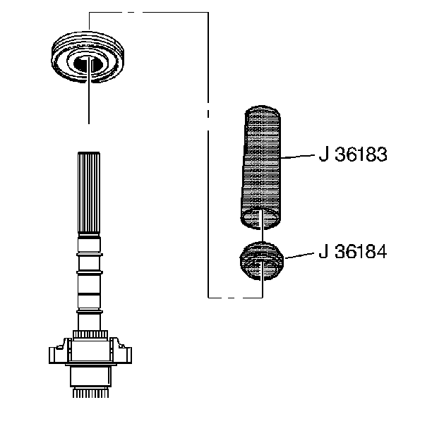
- Install the 5th/Reverse
speed gear synchronizer assembly.
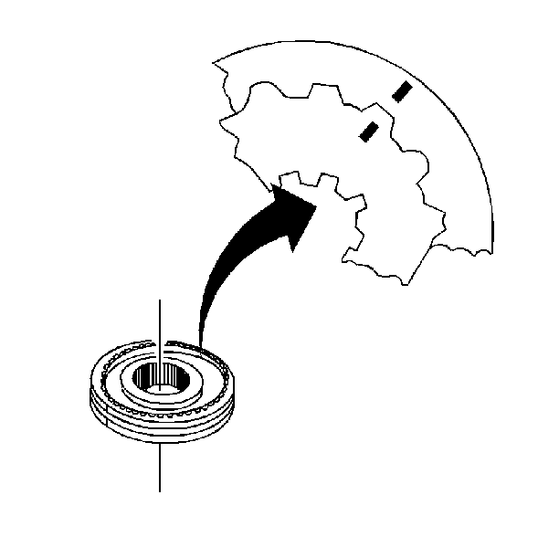
| 4.1. | Inspect the scribe marks for the correct positions. |
| 4.2. | Position the spiral lock ring towards the reverse speed gear. |
| 4.3. | Manually align and engage the splines on the synchronizer hub
with the splines on the main shaft. |
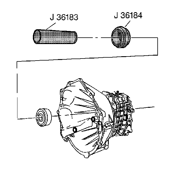
| 4.4. | Using a hydraulic press, the J 36183
, and the J 36184
, press the synchronizer until seated. |
| 4.5. | Remove all the metal shavings. |
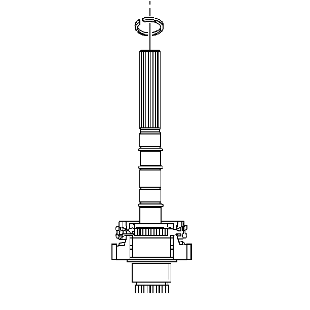
- Install a new mainshaft
snap ring.
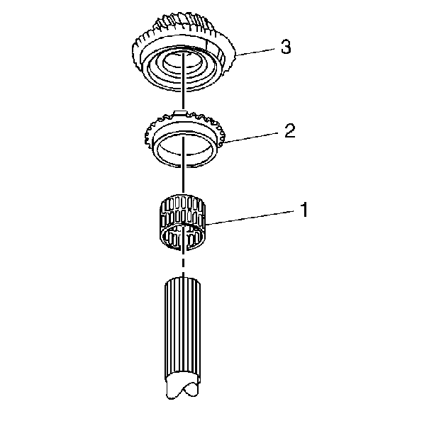
- Install the 5th speed
gear needle bearing (1).
- Install the synchronizer ring (2).
- install the 5th speed gear (3).
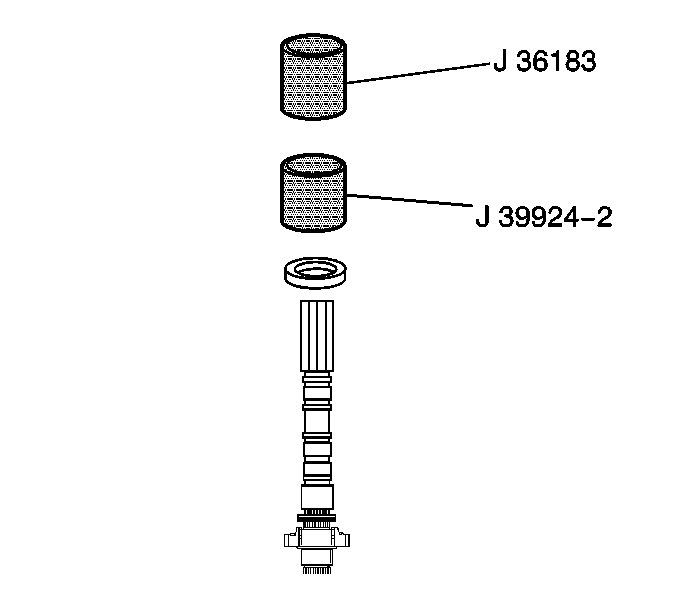
- UsingJ 39924-2
and J 36183
, install the 5th speed gear drag seal.
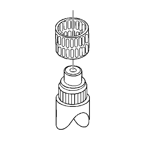
- Install the 1st speed
gear needle bearing assembly.
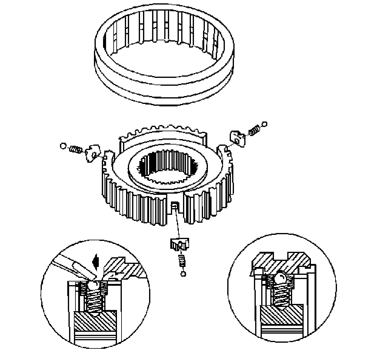
Important: The groove on the outside of the synchronizer sleeve must go towards
the 2nd speed gear. This prevents gear clash during 1st and 2nd speed gear
shifts. The teeth of the sleeve have different angles.
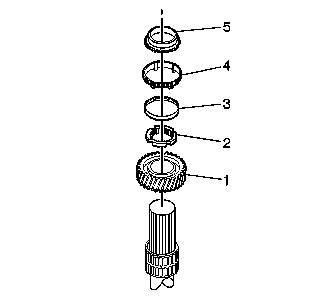
- Install the following
components:
| 11.1. | The 1st speed gear (1). |
| 11.2. | The synchronizer interim ring (2) with the teeth up |
| 11.3. | The reactor cone (3) with the flat side towards 1st gear |
| 11.4. | The blocker ring (4) with the teeth down |
| 11.5. | The synchronizer cone (5) with the flat side down |
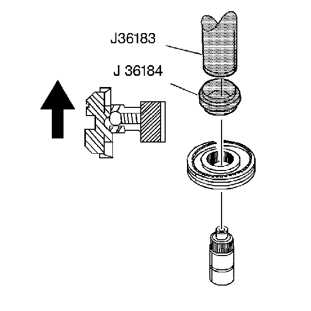
- Install the 1st/2nd speed
gear synchronizer assembly with both synchronizer rings.
| 12.1. | Inspect the scribe marks for the correct positions. |
| 12.2. | Manually align and engage the splines of the synchronizer hub
with the main shaft splines. |
| 12.3. | Using a hydraulic press, the J 36183
, and the J 36184
press the synchronizer hub onto the main shaft. |
| 12.4. | Start the press operation. |
| 12.4.1. | Stop pressing before the tangs engage. |
| 12.4.2. | Lift and rotate the gear. |
| 12.4.3. | Engage the synchronizer ring. |
| 12.5. | Press the synchronizer until seated. |
| 12.6. | Remove all the metal shavings. |
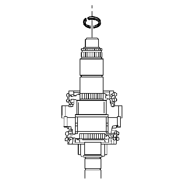
- Install a new mainshaft
snap ring.
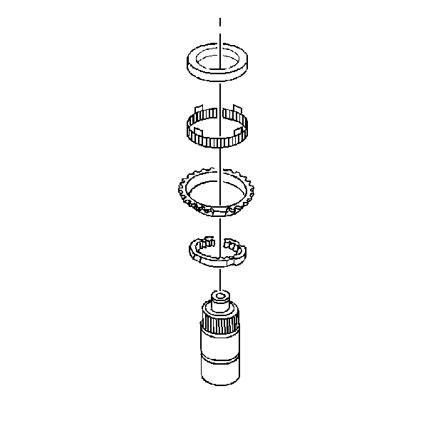
- Install the following
2nd gear synchronizer components:
| 14.1. | The synchronizer cone with the flat up |
| 14.2. | The blocker ring with the tangs up |
| 14.3. | The reaction cone with the wide flat portion up |
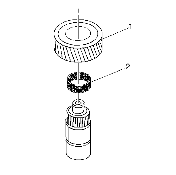
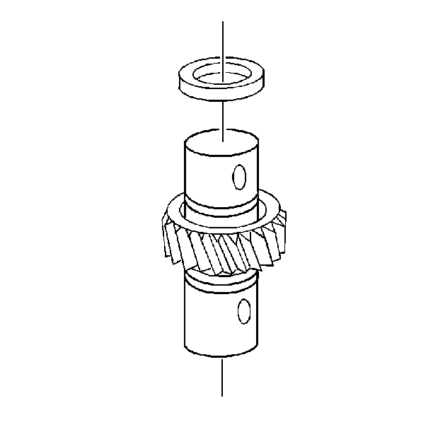
- Install the 2nd speed
gear needle bearing (2).
- Install the 2nd speed gear (1).
Ensure that the synchronizer ring gear teeth are positioned toward the
1st gear.
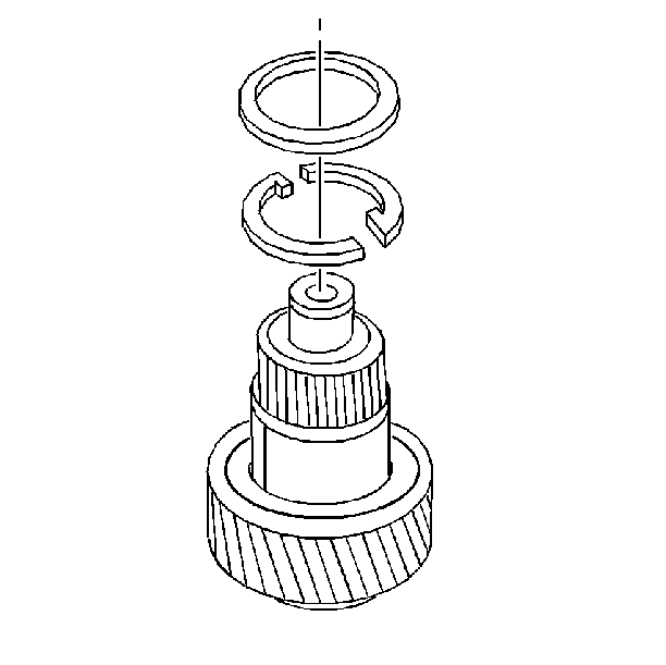
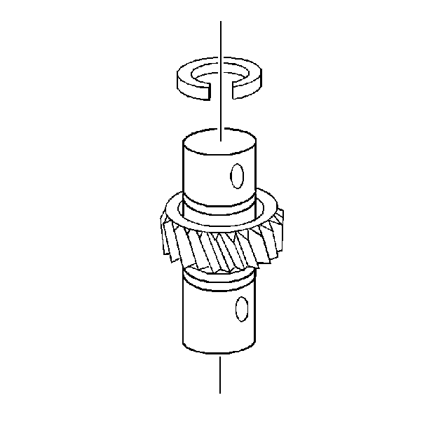
- Install the 2nd speed
gear 2-piece thrust washer. Ensure that the dots on the thrust washer are
facing up.
- Install the retainer ring. Ensure that the retainer ring is installed
around the washer.
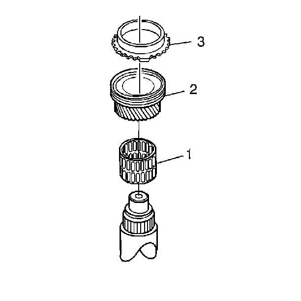
- Install the following
components:
| 19.1. | The 3rd speed gear needle bearing (1). |
| 19.2. | The 3rd speed gear (2). |
| 19.3. | The synchronizer ring (3). |
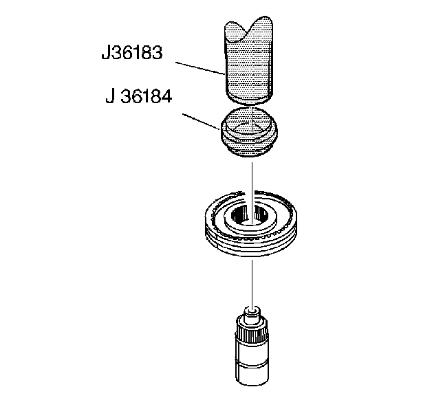
- Install the 3rd/4th speed
gear synchronizer assembly with both synchronizer rings. Ensure that the
groove in the synchronizer ring faces upward.
| 20.1. | Inspect the scribe marks for the correct positions. |
| 20.2. | Manually align and engage the splines of the synchronizer hub
with the main shaft splines. |
| 20.3. | Using a hydraulic press, the J 36183
, and the J 36184
press the synchronizer hub onto the main shaft. |
| 20.4. | Start the press operation. |
| 20.4.1. | Stop pressing before the tangs engage. |
| 20.4.2. | Lift and rotate the gear. |
| 20.4.3. | Engage the synchronizer ring. |
| 20.5. | Press the synchronizer until seated. |
| 20.6. | Remove all the metal shavings. |
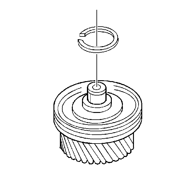
- Install a new mainshaft snap ring.
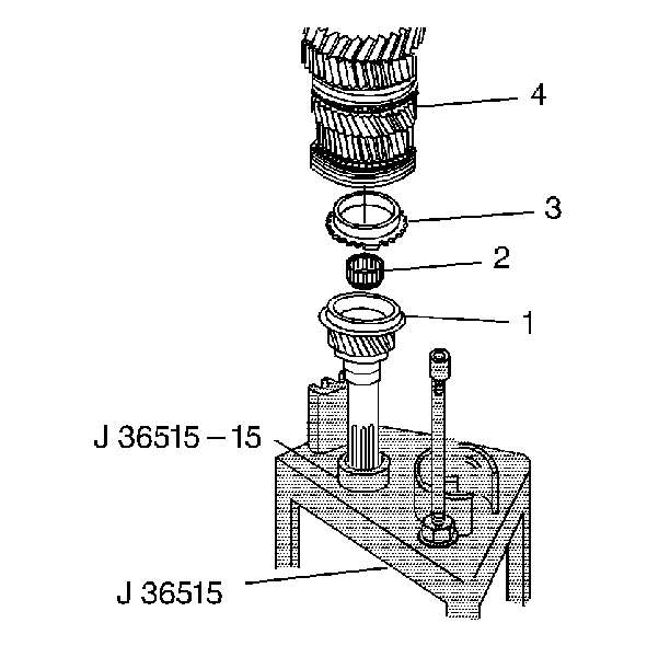
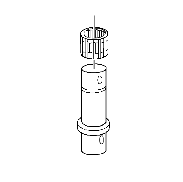
- Install the input shaft
(1) on the assembly fixture J 36515-15
and J 36515
:
- Install the pilot bearing (2) in the input shaft (1).
| 23.1. | Ensure the small diameter of the bearing is positioned toward
the input shaft. |
| 23.2. | Lubricate the pilot bearing with J 36850
. |
- Install the synchronizer ring (3) on the input shaft (1).
- Install the mainshaft assembly (4) onto the input shaft (1).
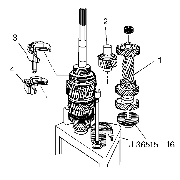
- Install the following
parts on the mainshaft and on the assembly fixture J 36515-16
:
| 26.1. | The countershaft assembly (1) |
| 26.2. | The reverse idler assembly (2) |
| 26.3. | The 1st/2nd speed gear shift fork (3) |
| 26.4. | The 5th/reverse speed gear shift fork (4) |
- Install the countershaft bearing on the countershaft.
Use the J 36850
in
order to retain the bearing.
The smaller diameter of the bearing cage is positioned toward the housing.
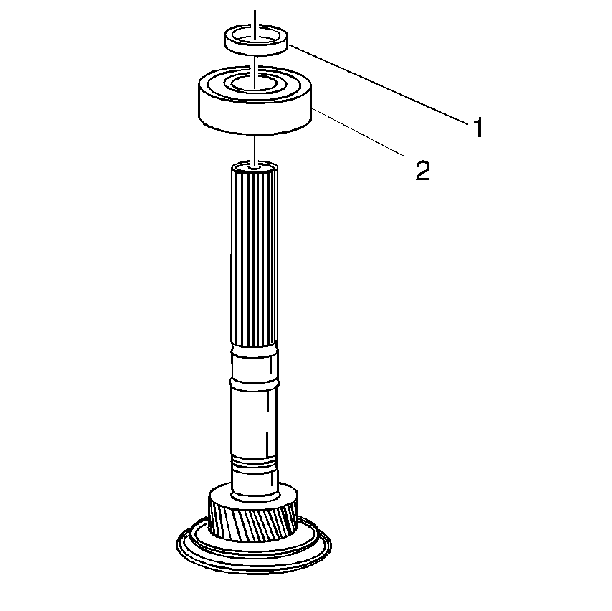
- If RWD vehicle, install
the output shaft bearing (2) on the mainshaft.
- Install a new mainshaft snap ring (1).
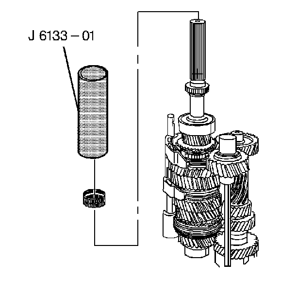
- If RWD vehicle, using J 6133-A
, install the reluctor
wheel onto the main shaft.
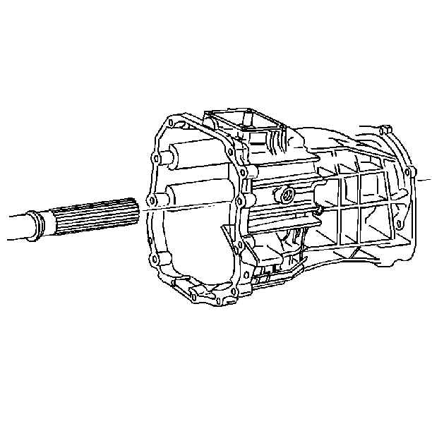
- If 4WD vehicle install the rear housing assembly.
| 31.1. | Make sure the reverse idler shaft is lined up with the hole in
the case. |
| 31.2. | Rotate the housing back and forth while pulling down. |
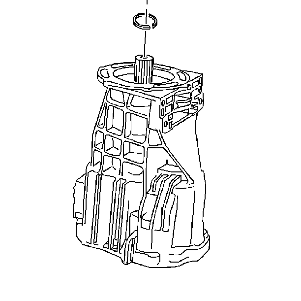
- If 4WD vehicle install
a new output shaft bearing snap ring.
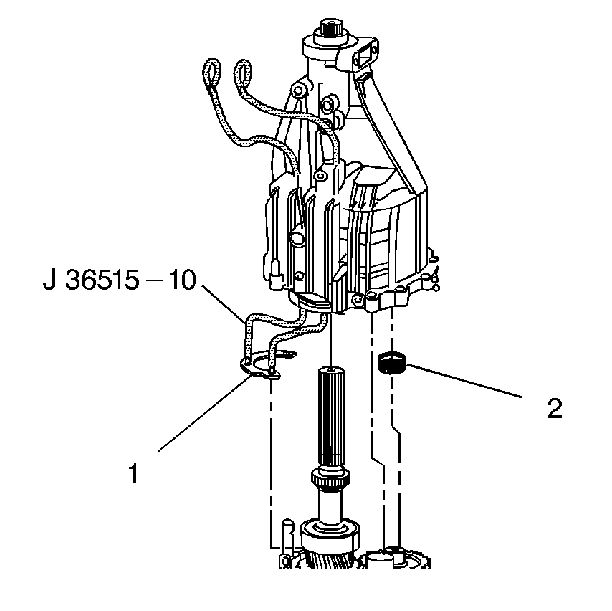
- If RWD vehicle, install
the following components:
| 33.1. | Install the J 36515-10
through the bolt holes in the rear housing. |
| 33.2. | Screw the threaded cable ends into the output shaft bearing retainer
(1). |
| 33.3. | Position the notch in the bearing retainer towards the oil delivery
tube assembly. |
- If RWD vehicle, install the rear housing assembly.
| 34.1. | Make sure the reverse idler shaft is lined up with the hole in
the case. |
| 34.2. | Rotate the housing back and forth while pulling down. |
| 34.3. | Pull up on the J 36515-10
while installing the rear housing. |
| 34.4. | Loosely install a rear bearing retainer bolt in the open hole.
This is to hold the bearing retainer in place when the J 36515-10
is removed. |
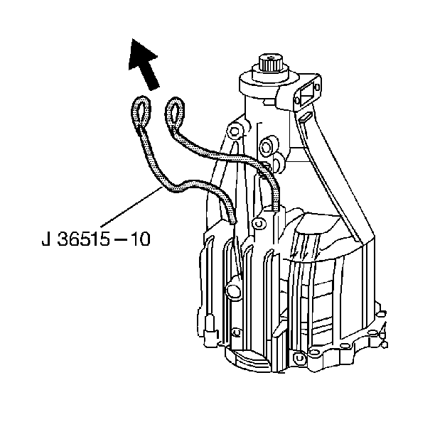
- Remove the J 36515-10
.
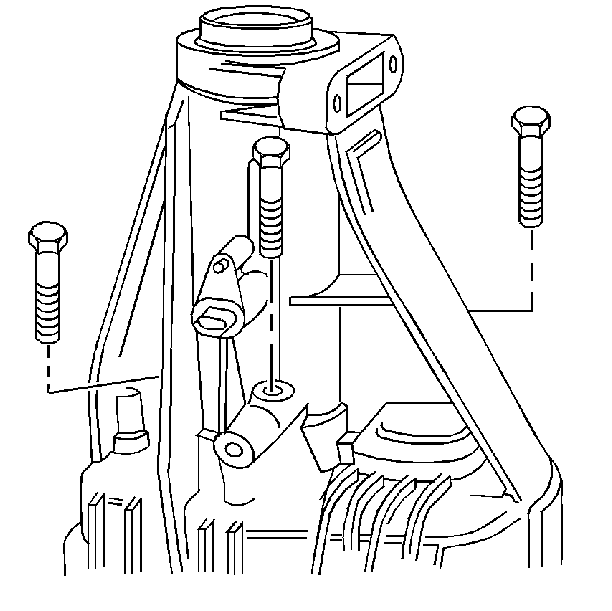
- Install the three rear
bearing retainer bolts.
Apply threadlocker GM P/N 12345382 to the bolt threads.
Tighten
Tighten the rear bearing retainer bolts to 22 N·m (16 lb ft).
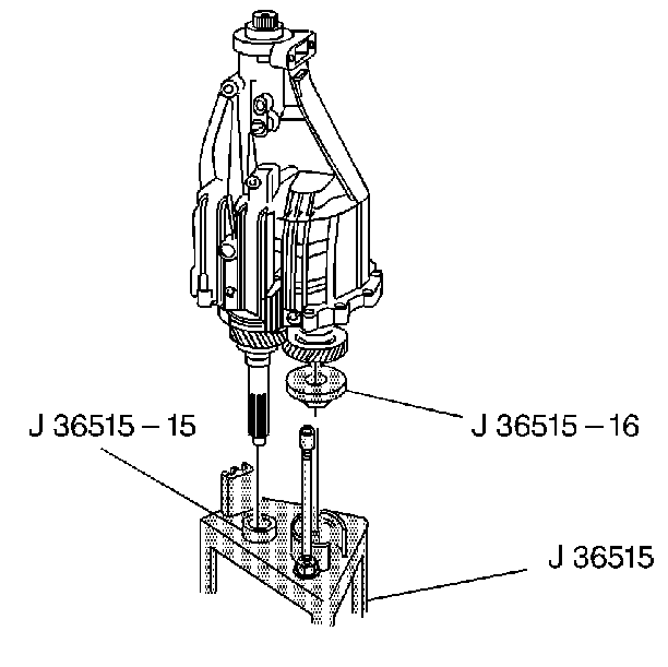
- Lay the housing assembly
down on a workbench.
- Remove the rear housing assembly from the J 36515
, the J 36515-15
, and the J 36515-16
.
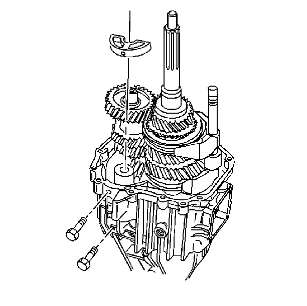
- Install the following
components:
| 39.1. | The idler shaft support |
| 39.2. | The idler shaft bolts |
Apply threadlocker GM P/N 12345382 or equivalent to the bolt
threads.
| 39.3. | Line up the bolt threads in the idler shaft support with the bolt
hole. |
| 39.4. | Hold the reverse idler shaft against the idler support while tightening
the bolts. |
Tighten
Tighten the bolt to 22 N·m (16 lb ft).
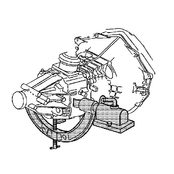
- Install the transmission
holding fixture on the transmission.
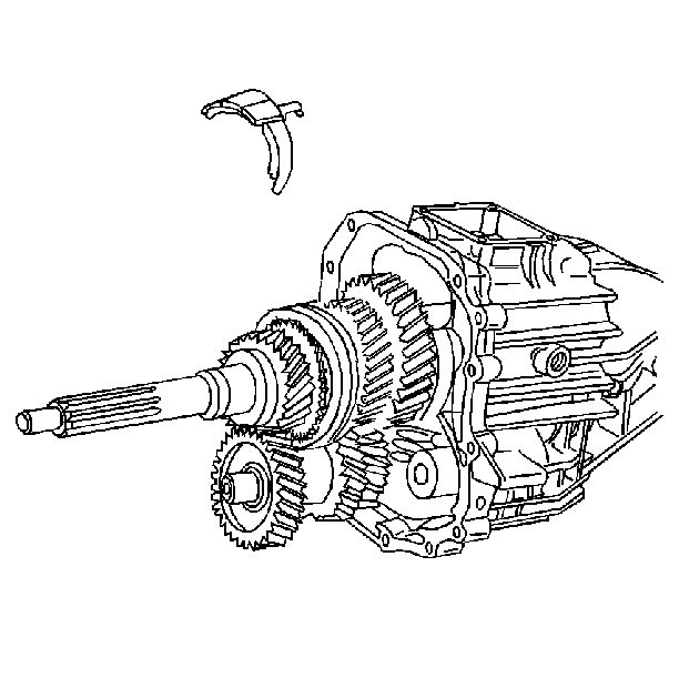
- Install the 3rd/4th speed
gear shift fork onto the 3rd/4th speed gear synchronizer sleeve.
Align all three insert notches.
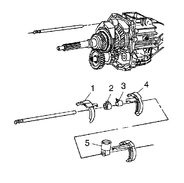
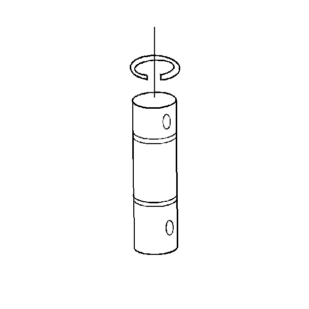
- Slide the shift shaft
through the following parts:
| 42.1. | The 3rd/4th speed gear shift fork (1). Ensure that the detent
reliefs in the shift shaft point out. |
| 42.2. | The shift lever (2). |
| 42.3. | The block-out bushing (3). |
| 42.4. | The 1st/2nd speed gear shift fork (4). |
| 42.5. | The shift socket (5). |
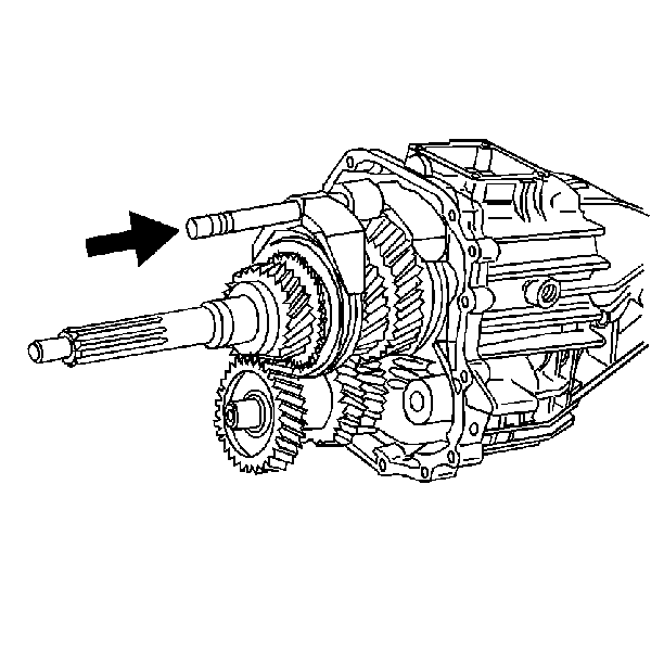
- Slide the shift shaft
all the way into the housing.
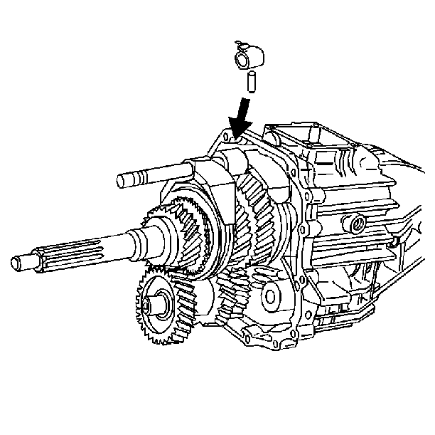
- Install a new short roll
pin into the shift lever. The end of the spiral must face toward the direction
of the thrust.
| 44.1. | Rotate the shift shaft and the shift lever/block-out bushing assembly.
Ensure the roll pin holes are aligned and horizontal. |
| 44.2. | Support the shift shaft while installing the roll pin. |
| 44.3. | Install the roll pin flush with the shift lever. |
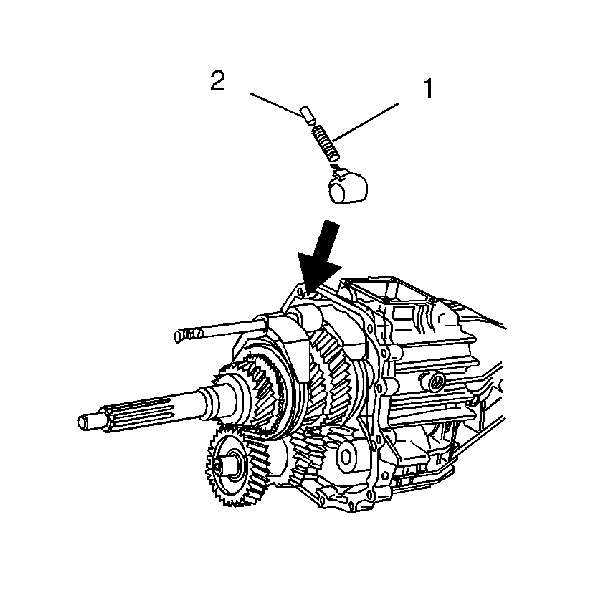
- Install the detent spring
and the ball plunger into the hole in the shift lever.
| 45.1. | Rotate the shift shaft counterclockwise. The shift lever should
be almost into the 5th/Reverse speed gear insert notch. |
| 45.2. | Install the spring (1) and the ball plunger (2) into the shift
lever. |
| 45.3. | Rotate the shift shaft until the shift lever aligns with the 3rd/4th
speed gear insert. |
Important: Excessive force peens the shift shaft and damages the shift shaft bearing
causing increased shift effort.
Important: Use the rear roll pin hole (2) on transmissions to be installed on S/T
(small) trucks.
Use the front roll pin hole (1) on transmissions to be installed on
C/K (large) trucks.
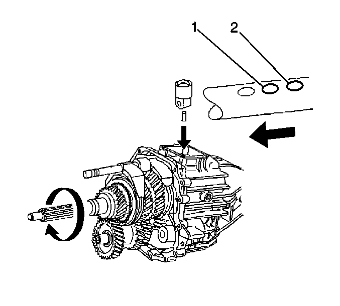
- Install the shift shaft
and shift shaft socket and roll pin.
| 46.1. | Align the holes in the shift shaft socket and the shift shaft. |
| 46.2. | Drive the roll pin flush with the bottom of the shift shaft socket. |
Important: The smaller diameter of the bearing cage goes into the bearing race.
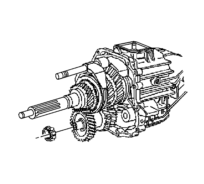
- Install the countershaft bearing onto the counter shaft.
Ensure the smaller diameter side of the bearing is positioned toward
the front case half.
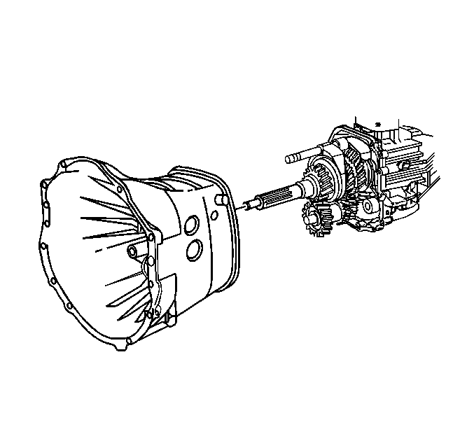
- Apply gasket maker GM P/N 1052943
or equivalent to the front housing sealing surface.
- Install the front housing to the rear housing.
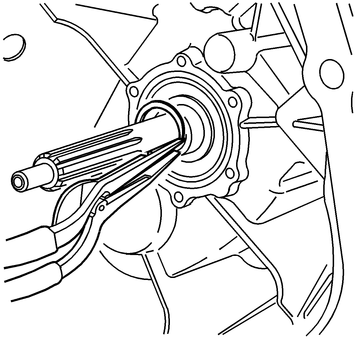
- Install a new snap ring
on the input shaft. It may be necessary to pull out on the input shaft
in order to install the snap ring.
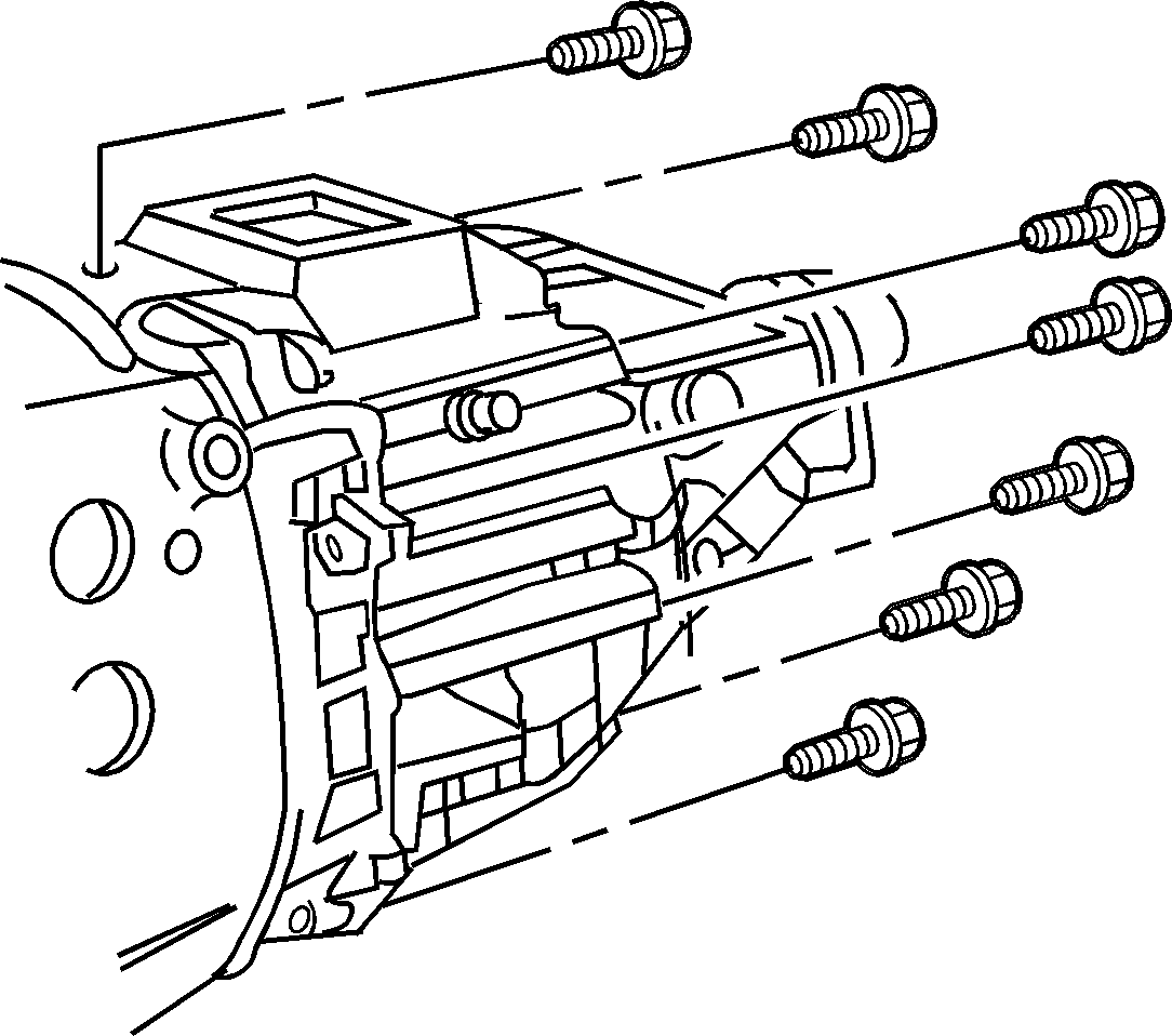
- Install the housing bolts
except for the bottom two.
Do not tighten the bolts.
Important: Do not allow sealant into the oil return hole in the housing or bearing
retainer.
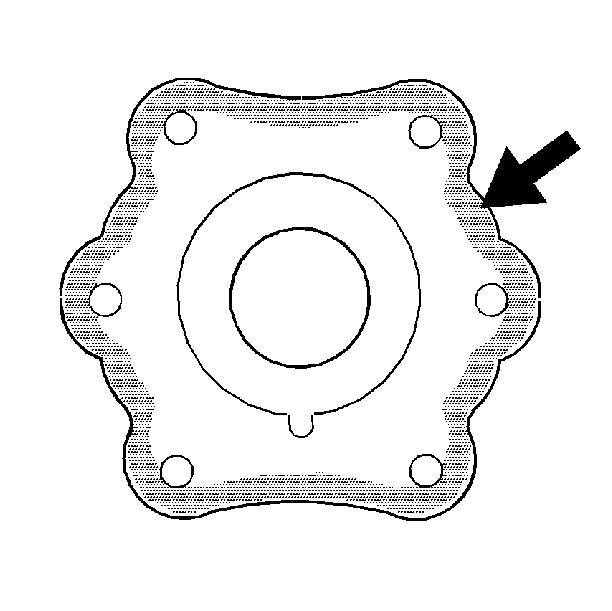
- Apply RTV sealer GM P/N 12345739
or equivalent to the inside edge of the bearing retainer mating surface.
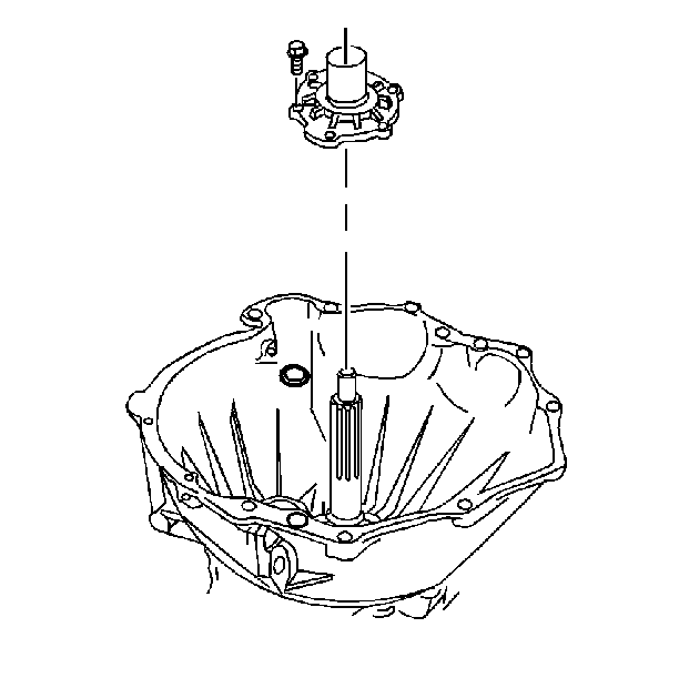
- Install the input shaft
bearing retainer to the housing with six bolts.
Align the retainer oil drain hole with the drain hole in the housing.
Tighten
Tighten the retainer bolts to 14 N·m (10 lb ft).
- Rotate the input shaft a few turns to align the transmission bearings
and to test for any excessive binding.
- Tighten the front to rear housing bolts.
Tighten
Tighten the housing bolts to 35 N·m (26 lb ft).
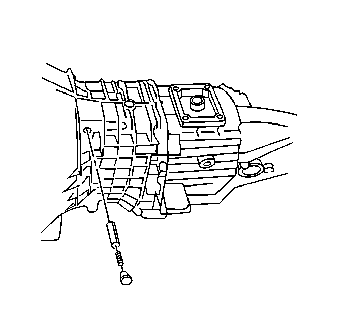
- Install the following
components:
| 56.1. | The shift shaft detent plunger |
| 56.2. | The shift shaft detent spring |
| 56.3. | The shift shaft detent plug |
Apply teflon pipe sealant GM P/N 12346004 or equivalent to the
detent plug.
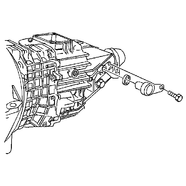
- If RWD vehicle, coat the
speed sensor O-ring with Synchromesh Transmission Fluid GM P/N 12345349
or equivalent.
- Install the speed sensor, O-ring, and bolt.
Tighten
Tighten the bolt to 9 N·m (80 lb in).
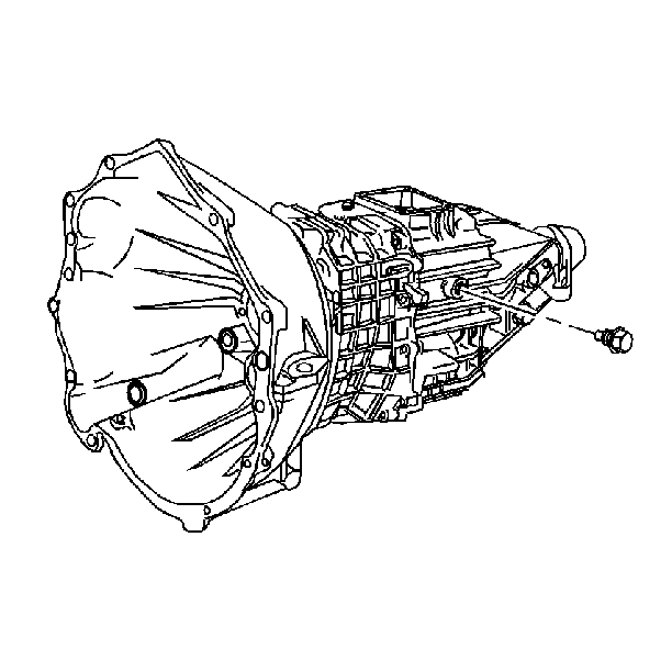
- Install the backup lamp
switch.
Apply teflon pipe sealant GM P/N 12345349 or equivalent to the
threads of the backup lamp switch.
Tighten
Tighten the switch to 14 N·m (10 lb ft).
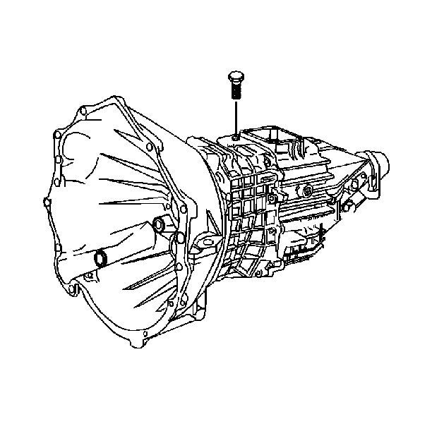
- Install the shift shaft
block-out bushing pin.
Tighten
Tighten the bolt to 25 N·m (18 lb ft).
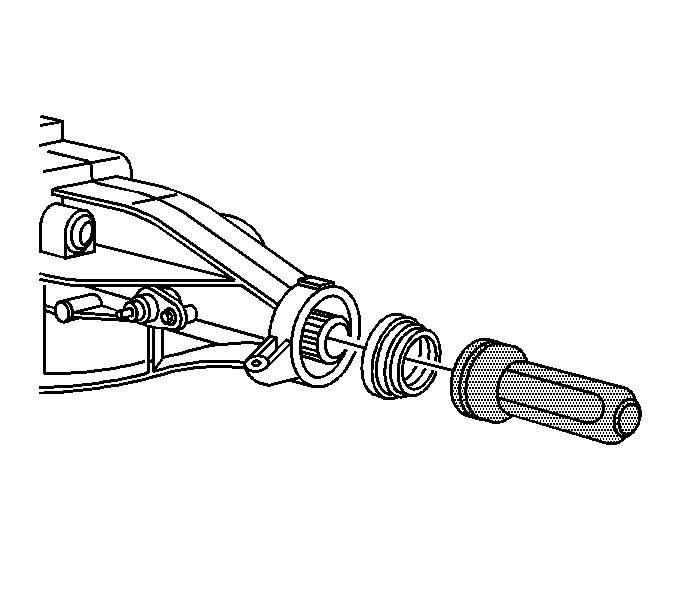
- If RWD vehicle, using
the J 36503
, install the
slip yoke oil seal.
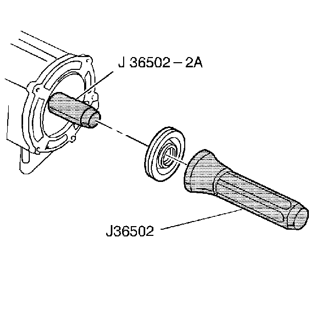
- If 4WD vehicle, install
the J 36502-2A
on the output
shaft.
- Install the output shaft seal using the J 36502
.
- Remove the J 36502-2A
from the output shaft.
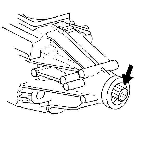
- Fill the space between
the seal lips with chassis grease.

- Remove the J 8763-B
and the J 36824
from the transmission.
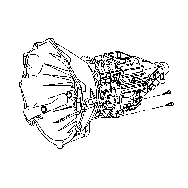
- Install the two remaining
rear to front housing bolts.
Tighten
Tighten the housing bolts to 35 N·m(26 lb ft).
- To prevent the transmission fluid from spilling while installing
the transmission in the vehicle, fill the transmission after installing with
Synchromesh Transmission Fluid GM P/N 12345349.


