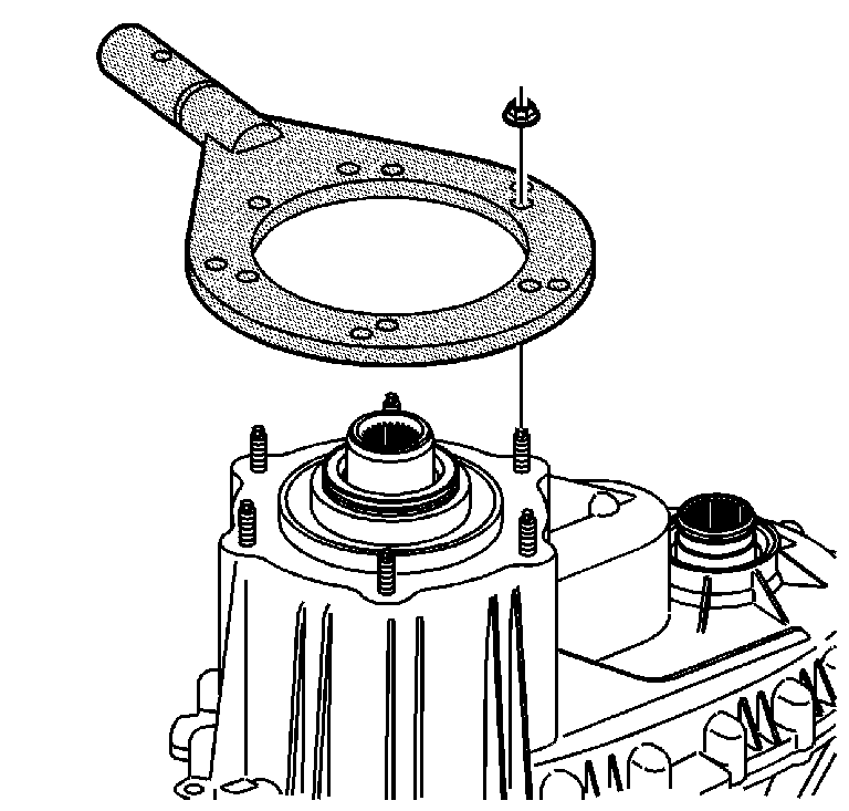
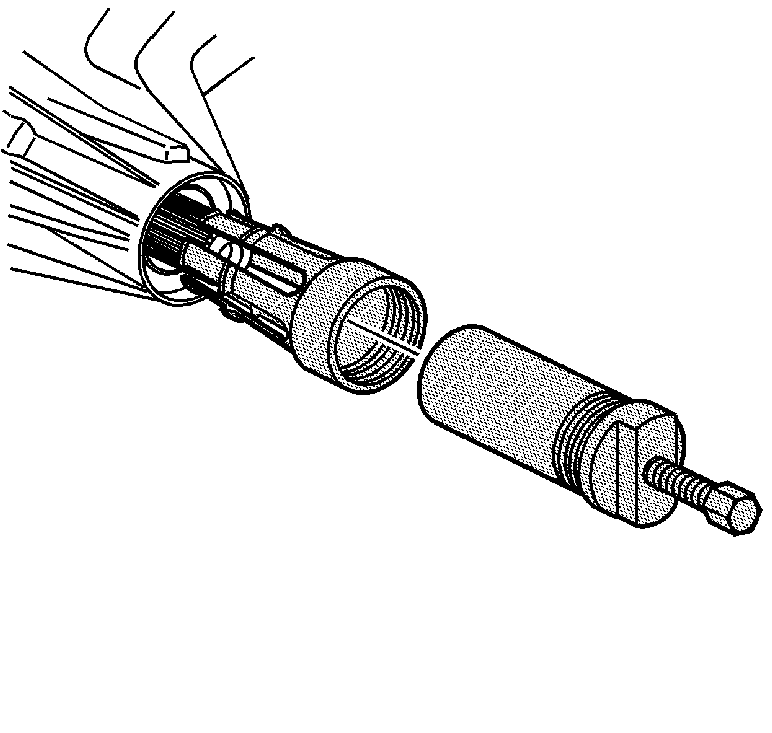
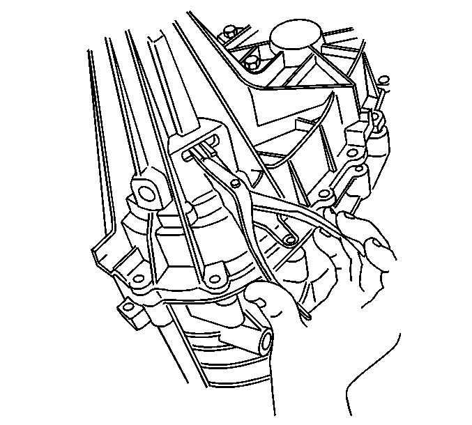
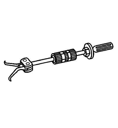
- Attach the J 45759
to the transfer case using the adapter studs. All of the transfer case disassembly
procedures can be performed with the case mounted to the J 45759
.
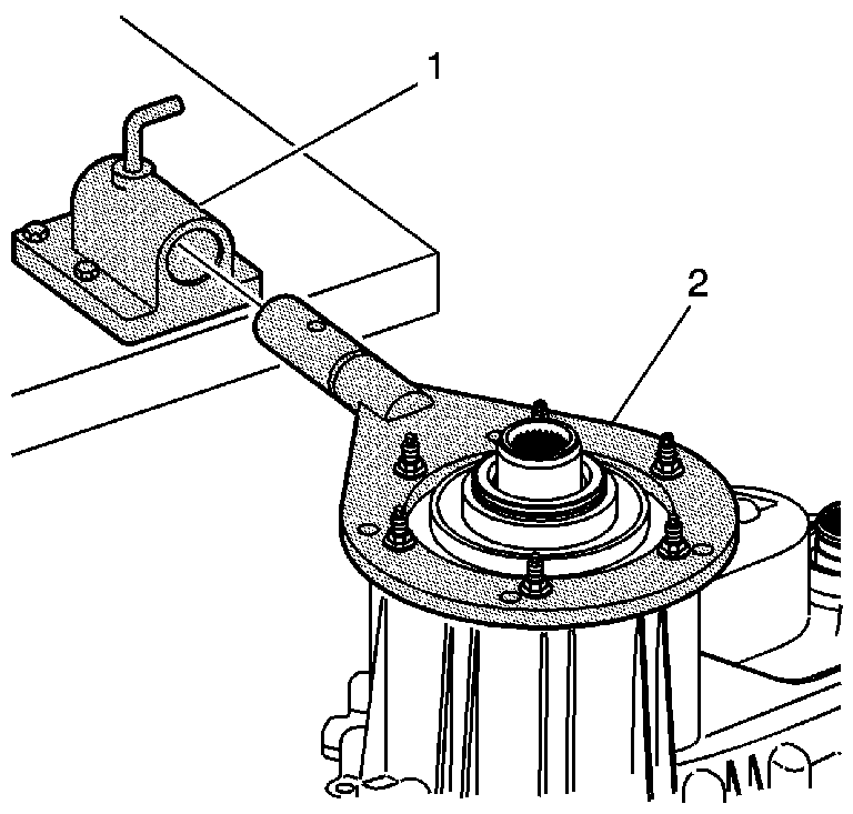
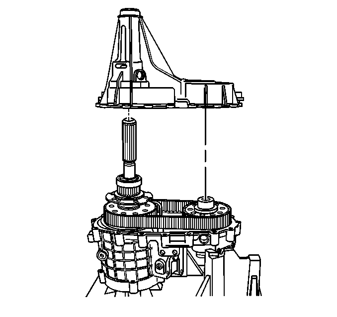
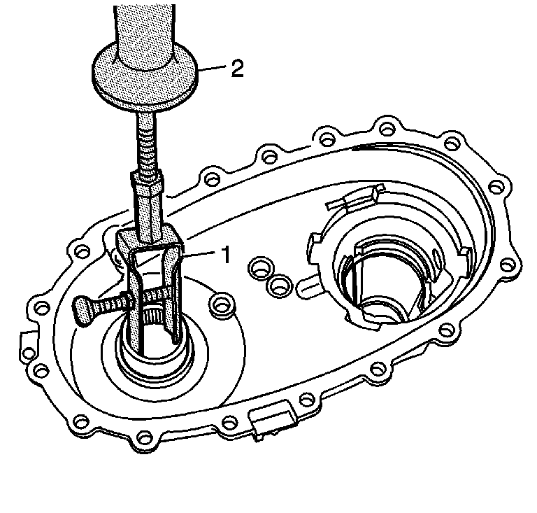
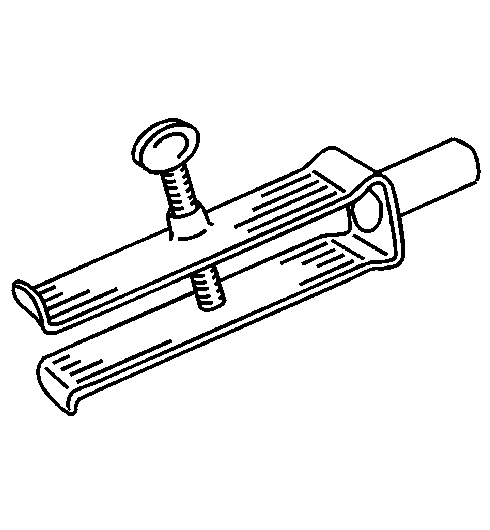
- Mount the J 3289-20
(1)
to a sturdy workbench.
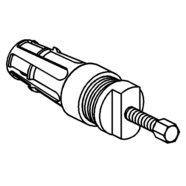
- Install the J 45759
(2)
into J 3289-20
(1) and secure with
pivot pin.
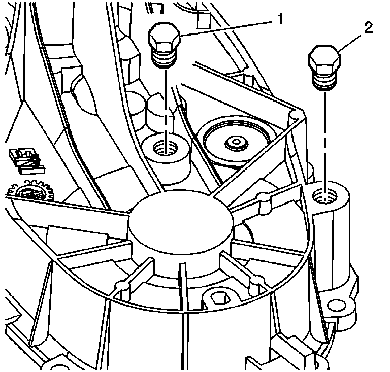
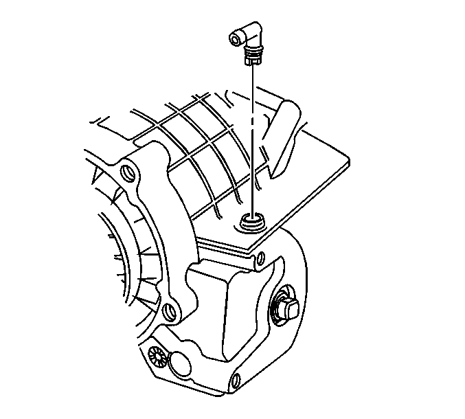
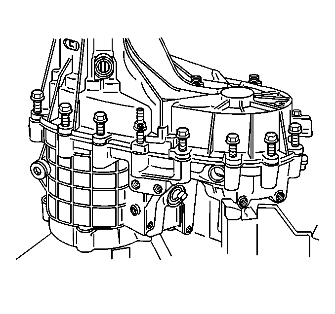
- Remove the fill plug (1) and the
drain plug (2) and drain the transfer case fluid.
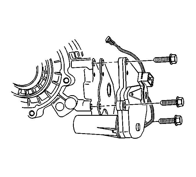
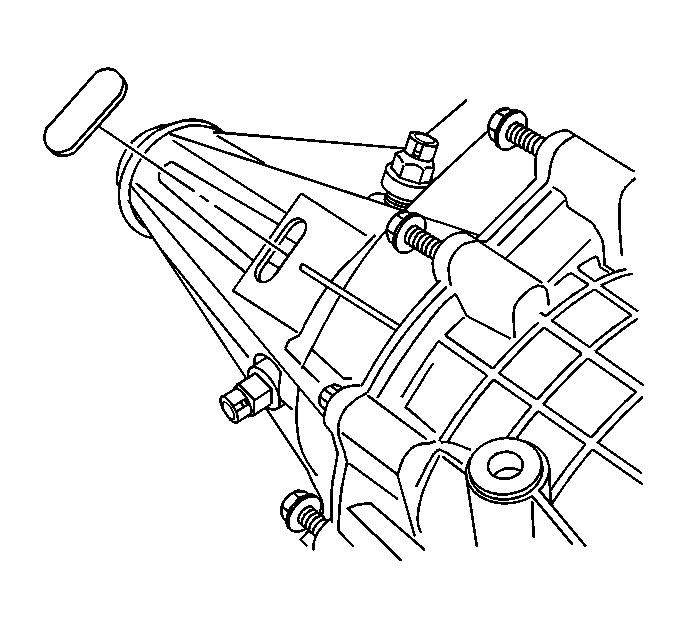
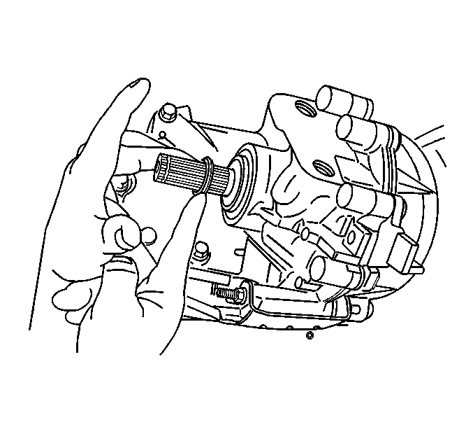
- Remove the encoder motor mounting
bolts.
- Remove the encoder motor assembly.
- Remove the actuator insulator gasket.
- Remove the vent and the seal, only
if damaged.
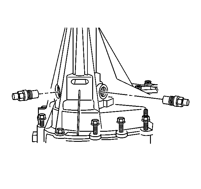
- Remove the rear vehicle speed sensors
(VSS).
- Remove the front VSS.
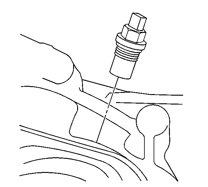
- Remove the access hole plug.
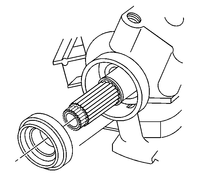
- Remove the front output shaft dust
seal.
Notice: Do not damage the sealing surfaces of the transfer cases or the shafts
when prying the seals for removal. Damaging the sealing surface may cause
leakage or require replacement of the damaged component.
- Remove the
front output shaft seal.
Notice: Do not damage the sealing surfaces of the transfer cases or the shafts
when prying the seals for removal. Damaging the sealing surface may cause
leakage or require replacement of the damaged component.
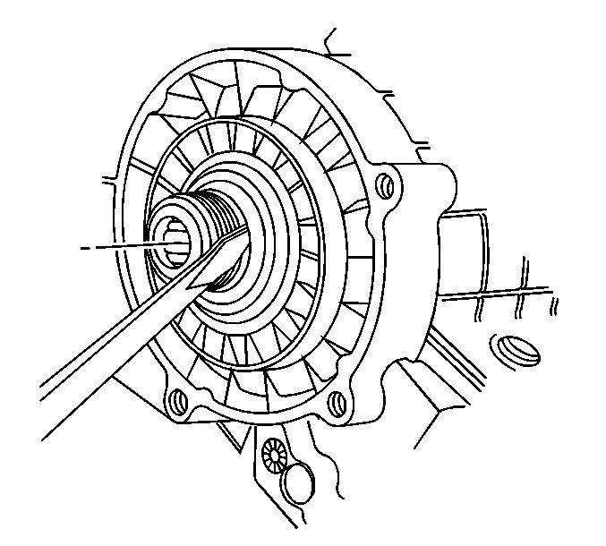
- Remove the
input shaft seal by prying it out of the front case.
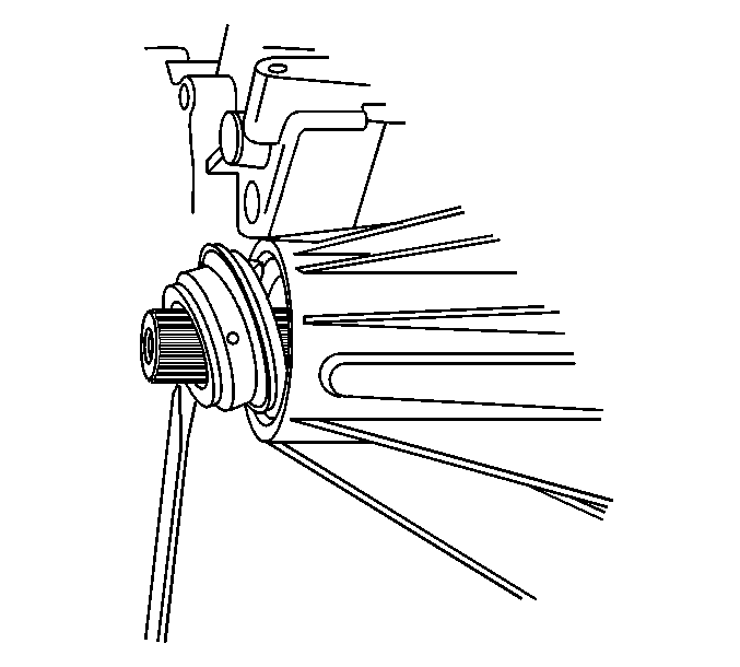
- Remove the rear output shaft seal.
- Inspect the rear output shaft bushing
for scoring or wear.
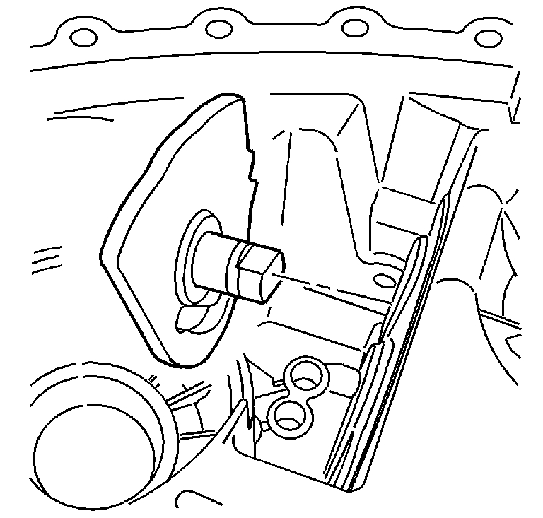
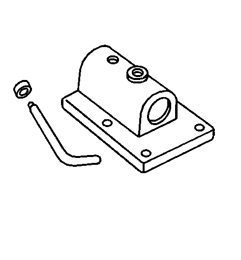
- Remove the rear output shaft bushing using the J 45380
.
| • | Install the finger section of the J 45380
in front of the bushing. |
| • | Install the tube and forcing screw assembly to the finger section.
Ensure the forcing screw is backed out. |
| • | Using a wrench on the forcing screw, remove the rear output shaft
bushing. |
- Remove the transfer case retaining
bolts and washers.
Mark the location of any brackets.
Notice: Refer to Machined Surface Damage Notice in the Preface section.
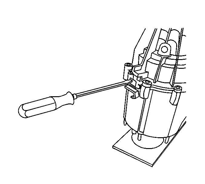
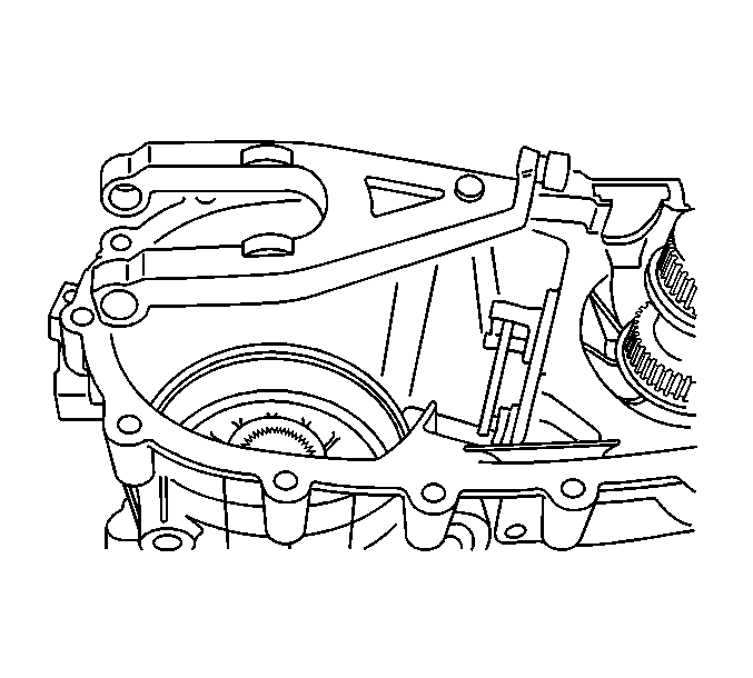
- Insert a flat-bladed screwdriver into the slot on the left side
of the transfer case.
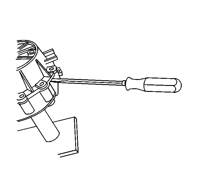
- Insert a flat-bladed screwdriver
into the slot on the right side of the transfer case.
- With equal pressure, press down on the screwdrivers in order to
separate the front case half and the rear case half.
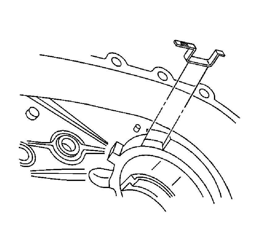
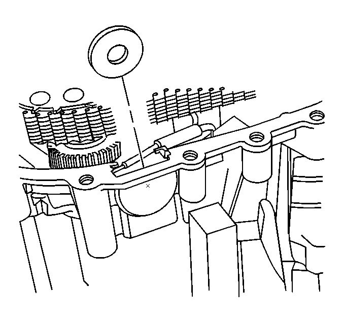
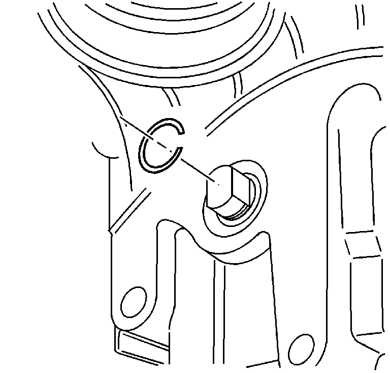
- Insert a pair of snap ring pliers
and release the outer retaining ring for the rear output shaft bearing.
- Remove the rear case half from the
front case half.
- Remove the oil pump wear sleeve, only
if it is worn or damaged.
- Remove the rear output shaft rear
bearing retaining ring.
- Remove the rear output shaft rear
bearing.
- Remove the rear output shaft speed
sensor reluctor wheel.
- Remove the magnet.
- Disconnect the oil pump suction pipe
from the oil pump screen.
- Remove the oil pump screen from the front case half.
- Remove the oil pump suction pipe from the oil pump inlet hole.
- Remove the oil pump suction pipe O-ring from the oil pump.
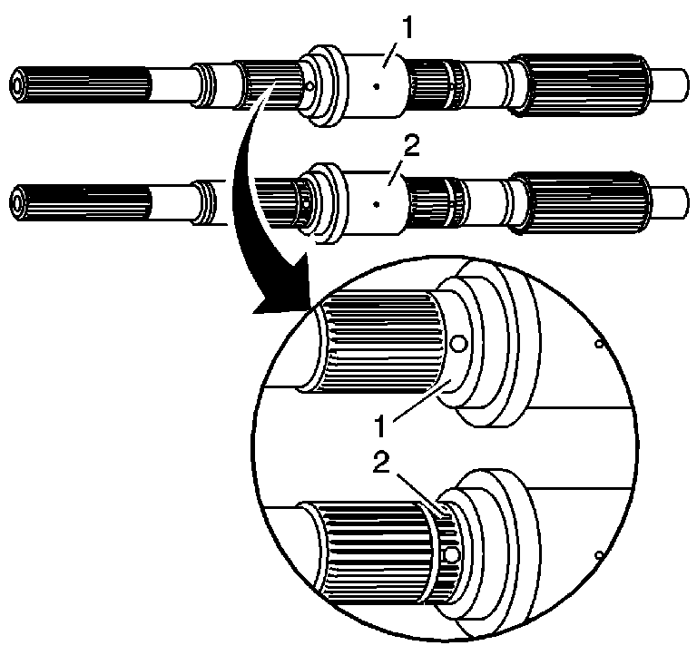
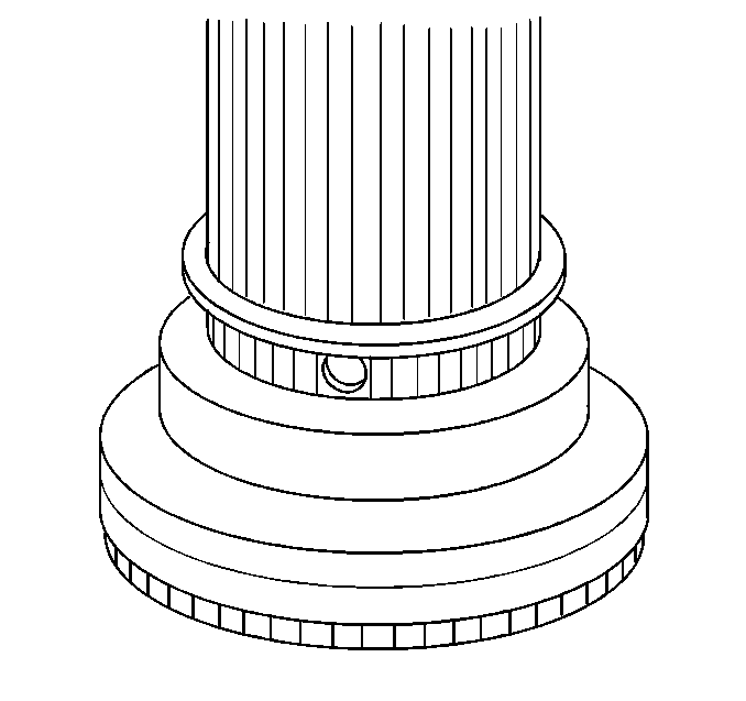
Important: The rear output shaft may be an original design (2) or the replacement
design (1). The original design rear output shaft (2) uses an
oil pump wave washer above the oil pump and a retaining ring under the oil
pump. The original design rear output shaft (2) is identified by the
splines in the area by the oil gallery hole. The replacement design rear output
shaft has a smooth area by the oil gallery hole. Ensure to follow the steps
for the correct rear output shaft.
- Inspect the rear output shaft to identify as an original design (2)
or the replacement design (1).
- If original design rear output shaft,
remove the oil pump wave washer.
- Remove the oil pump assembly.
- If original design rear output shaft,
remove the oil pump retaining ring.
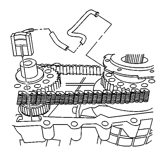
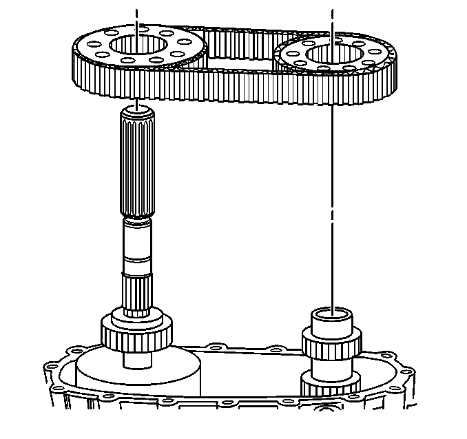
- Remove the drive sprocket retaining
ring.
- Remove the driven sprocket retaining
ring.
Important: If the chain and sprockets are to be used again, mark the relationship
of the chain to the sprockets in order to mark the wear patterns.
- Remove the chain and sprockets.
- Remove the chain from the drive sprocket and driven sprocket.
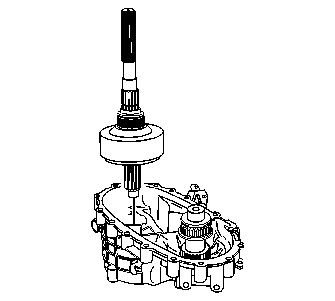
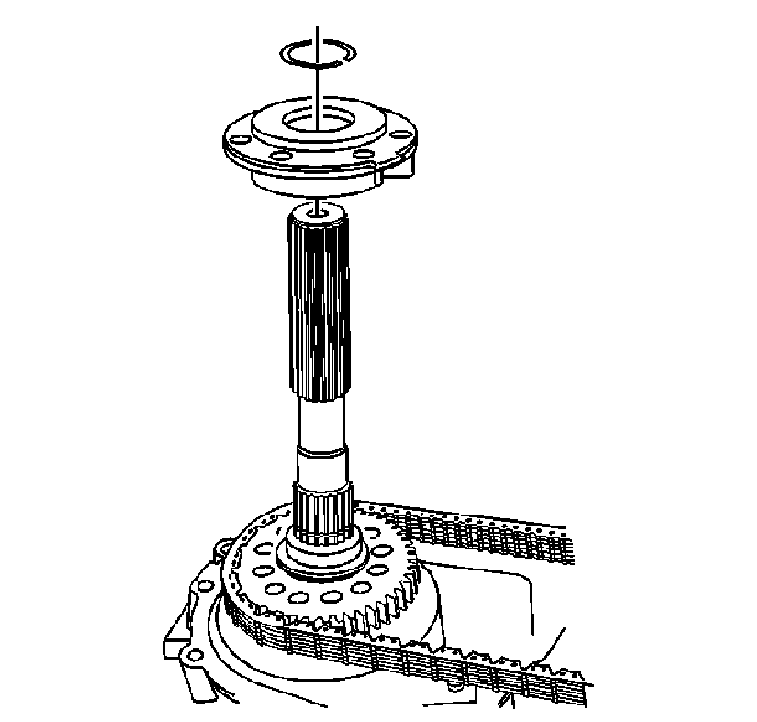
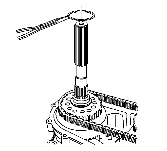
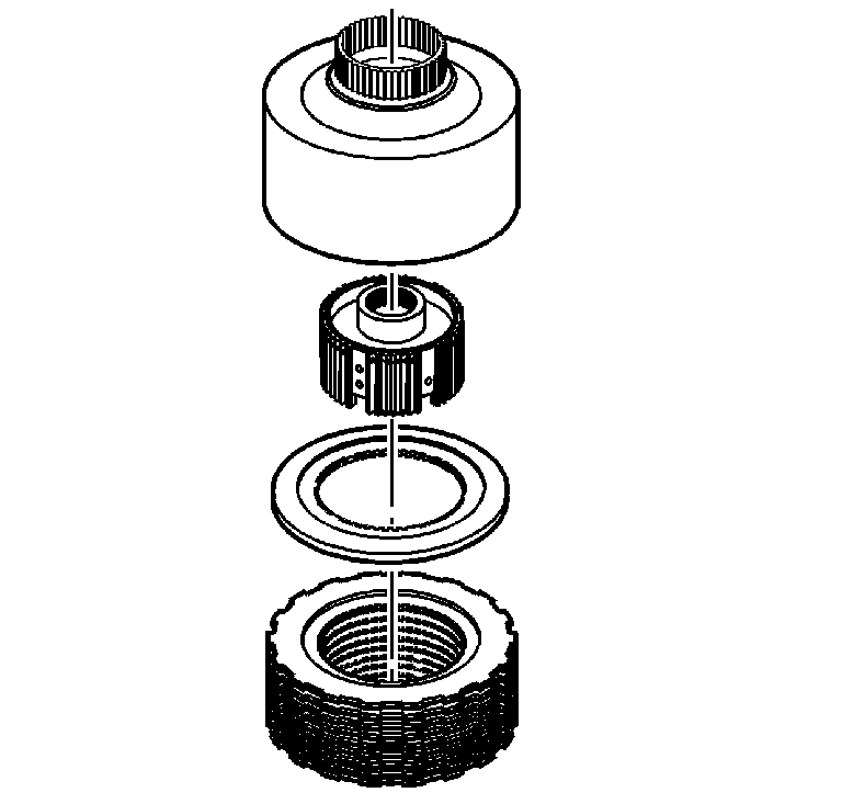
- Remove the rear output shaft assembly.
- Mount the rear output shaft assembly in a soft-jaw vise
with the input end up.
- Remove the clutch assembly retaining
ring. Push down on the clutch pressure plate to access the retaining ring.
- Remove the clutch pressure plate assembly.
- Remove the clutch pressure plate spring.
- Remove the clutch pressure plate bearing
with the clutch pressure plate hub from the clutch pressure plate.
- Inspect the bearing for being faulty.
Refer to
Transfer Case Cleaning and Inspection
.
- If the bearing is faulty, using a hydraulic press and a suitable
adapter, remove the clutch pressure plate bearing from the clutch pressure
plate hub.
- Discard the bearing after removal.
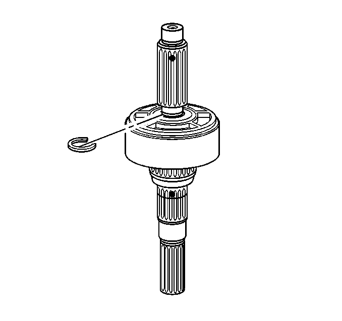
- Remove the clutch hub retaining ring.
- Remove the clutch housing and hub
assembly from the rear output shaft.
- Remove the clutch hub oil restrictor plate.
- Turn the clutch assembly over on a
workbench.
- Remove the clutch housing.
- Remove the clutch hub.
- Remove the clutch backing plate.
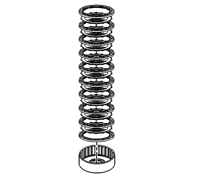
Important: Do not wash the clutch inner friction plates in cleaning solvent.
- Separate the clutch plates for inspection.
- Remove and discard the shim or shims.
- Remove the oil restrictor from the
rear output shaft, if replacing the shaft.
- Inspect the bearing in the clutch
housing for being faulty. Refer to
Transfer Case Cleaning and Inspection
.
- If the bearing is faulty, use a brass drift and a hammer to remove
the bearing.
- Remove both of the clutch lever pivot
pins along with the aluminum washers and O-ring seals.
- Remove the shift detent spring bolt.
- Remove the following components:
| • | The shift detent plunger plug O-ring seal |
| • | The shift detent spring |
| • | The shift detent plunger |
- Remove the clutch lever assembly.
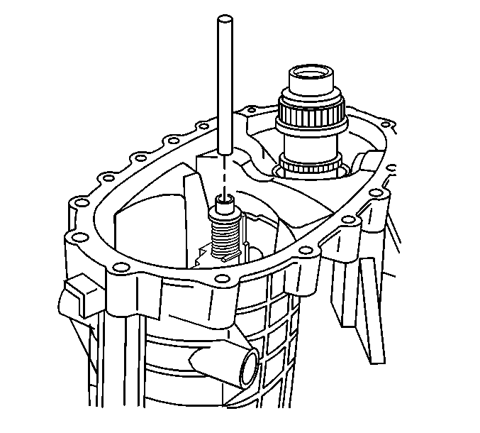
- Remove the shift fork shaft.
- Remove the range shift fork and the
range shift sleeve as an assembly.
It may be necessary to pry
the roller on the shift fork from the control actuator lever.
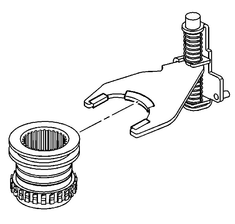
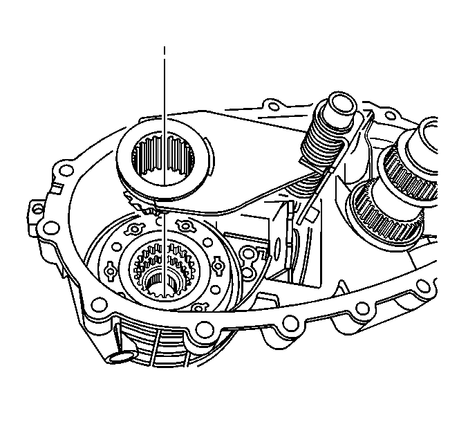
- Remove the range shift sleeve from
the range shift fork.
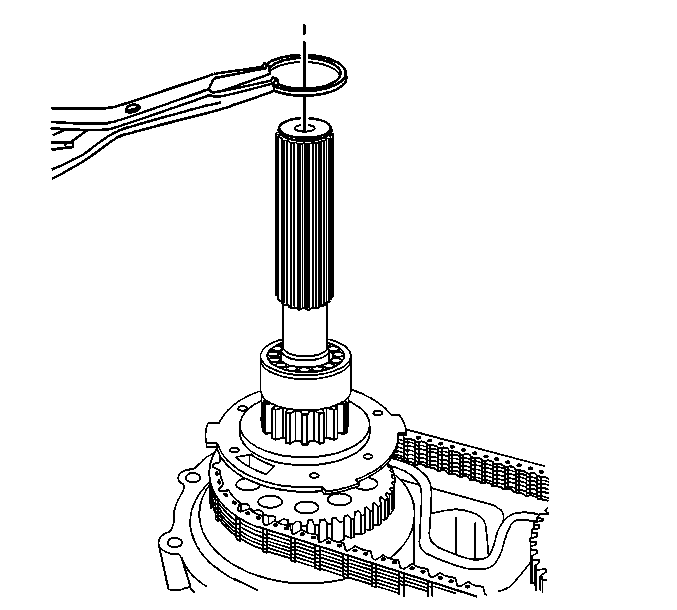
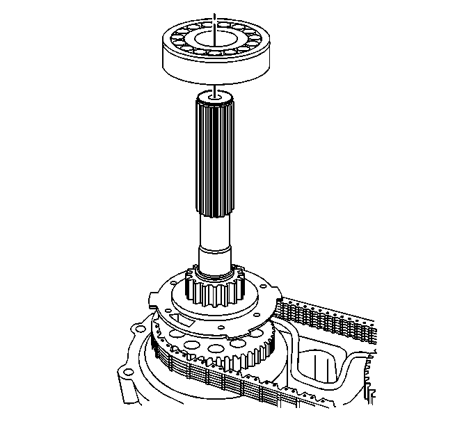
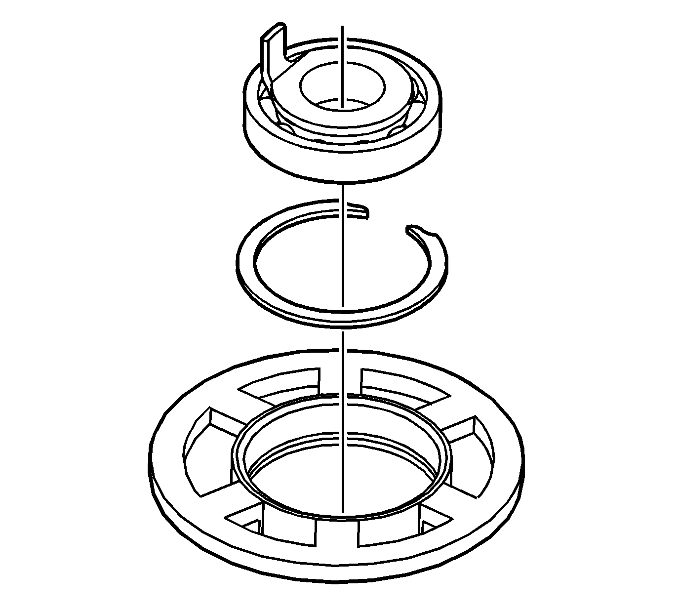
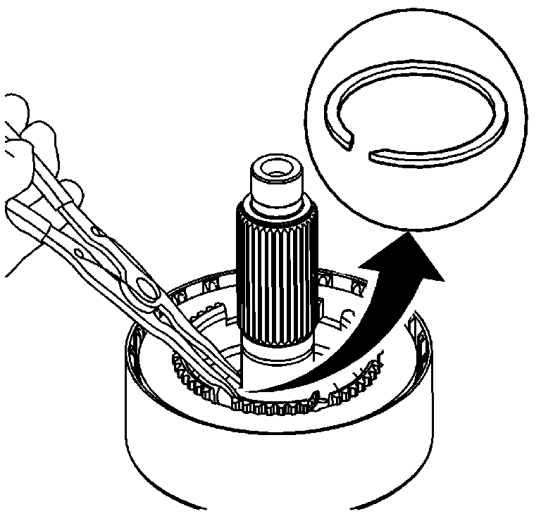
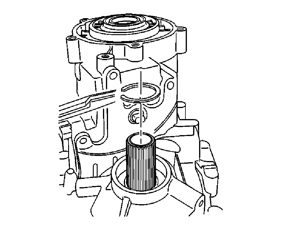
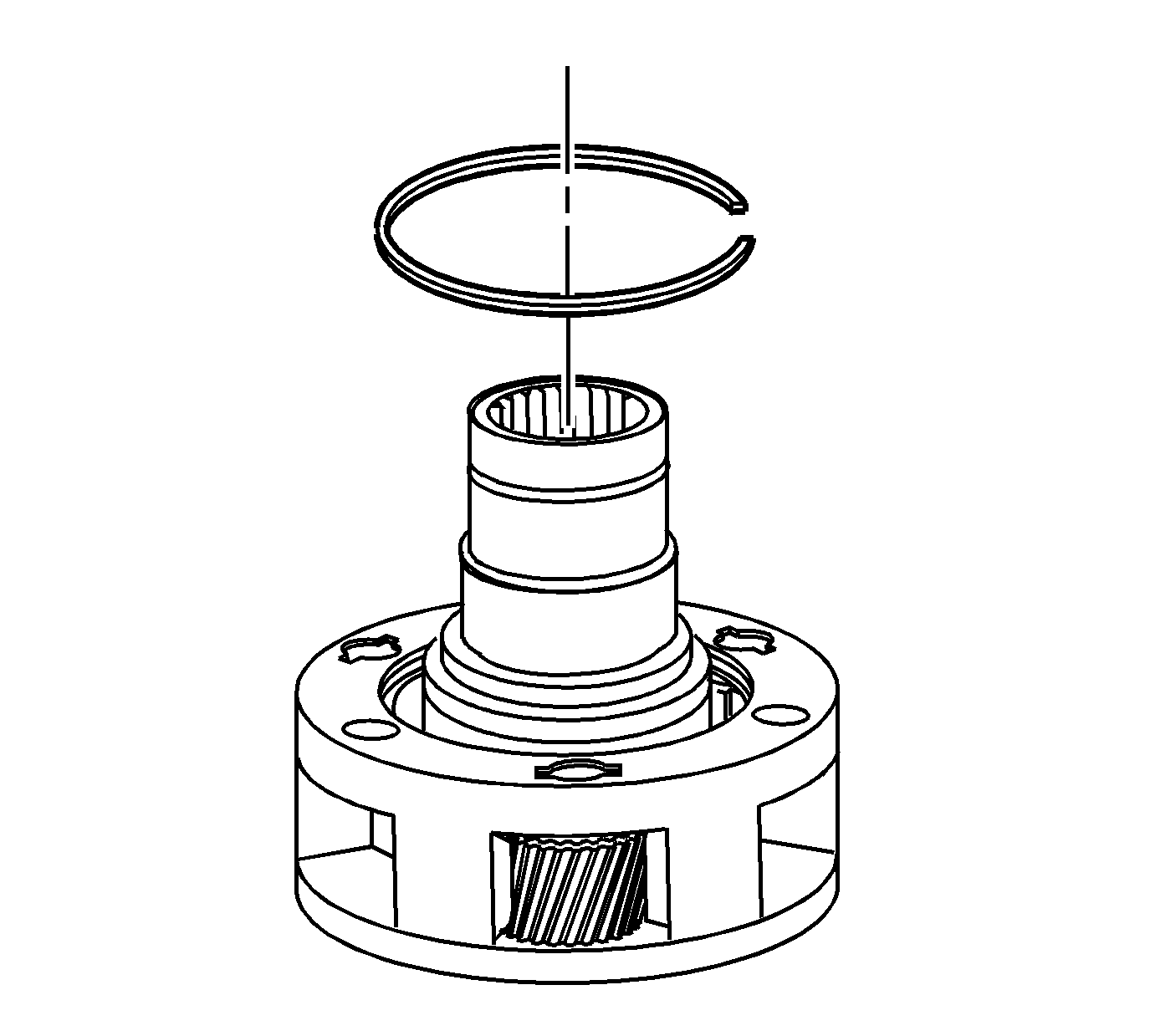
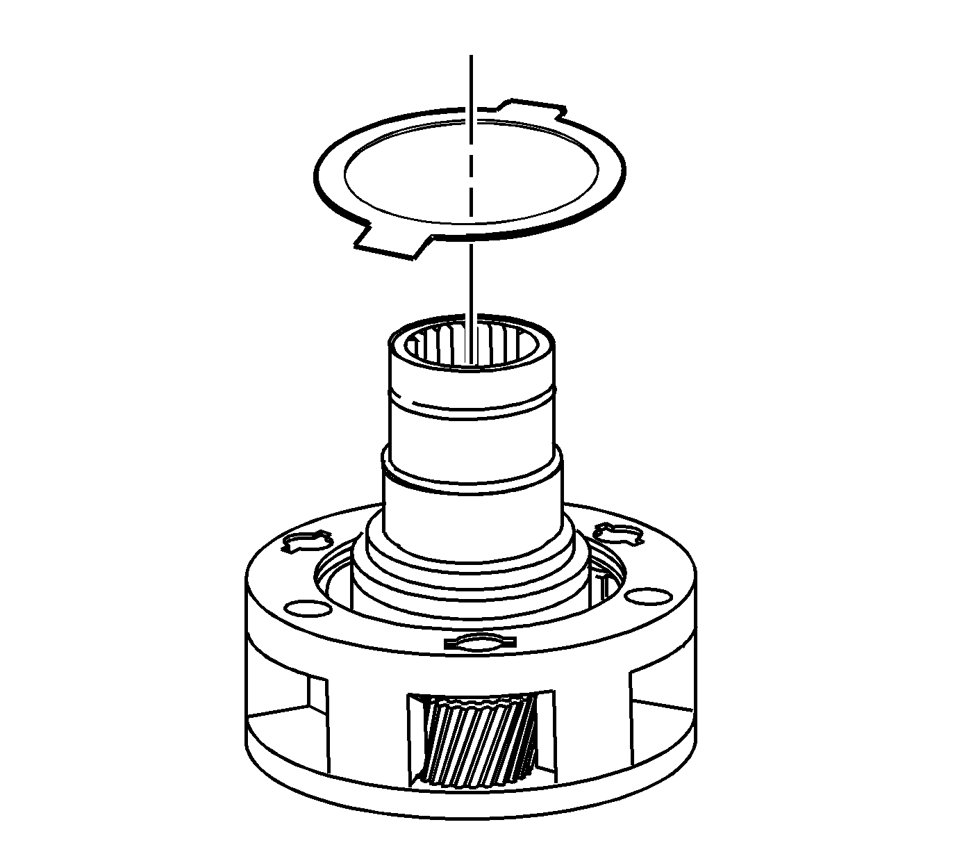
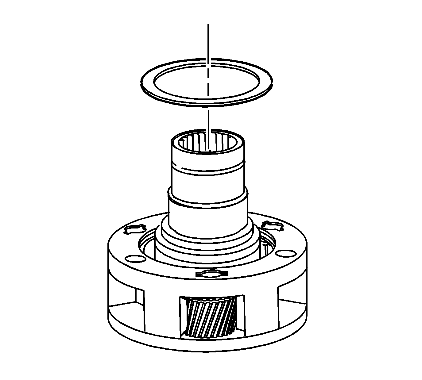
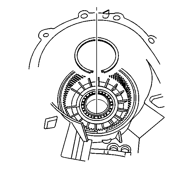
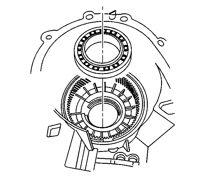
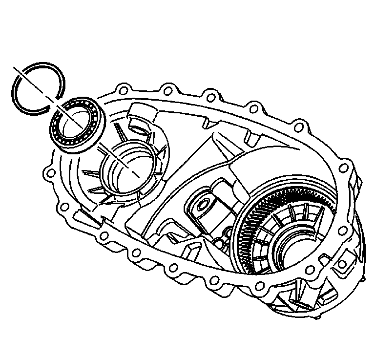
- Remove the outer retaining ring for
the input gear bearing.
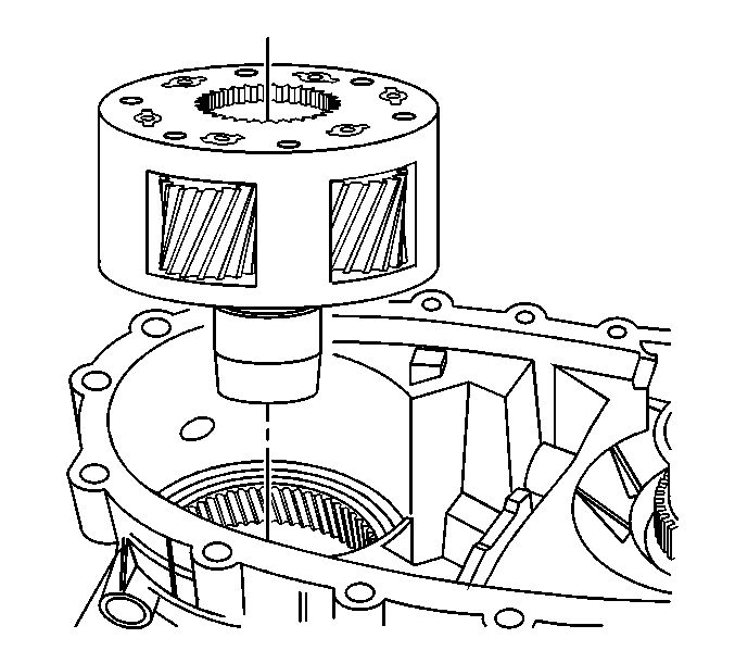
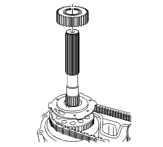
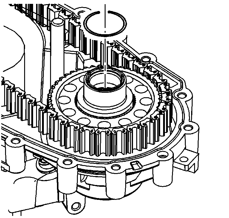
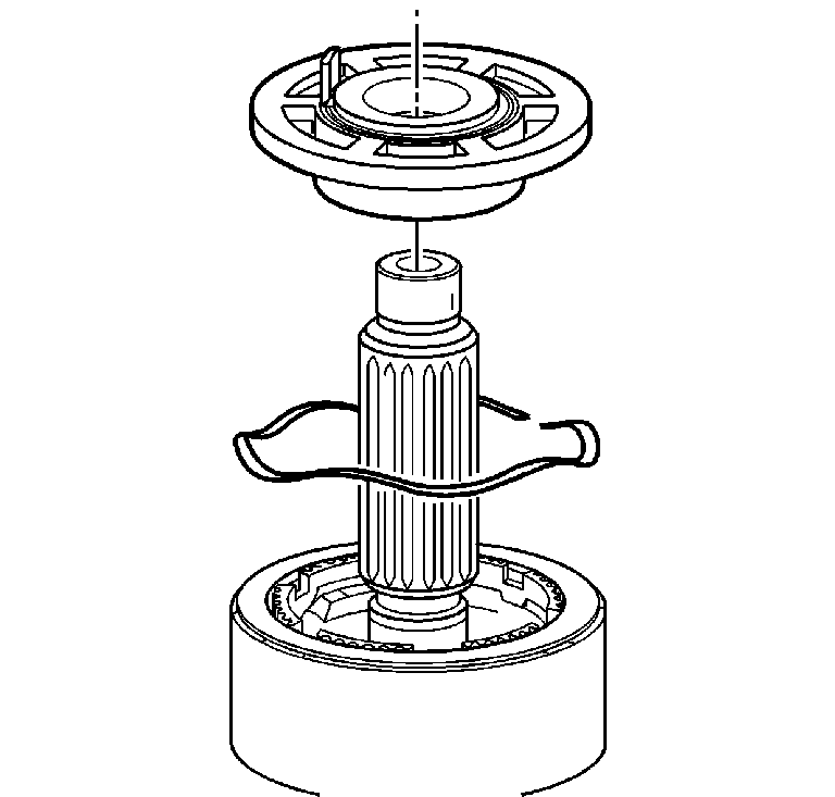
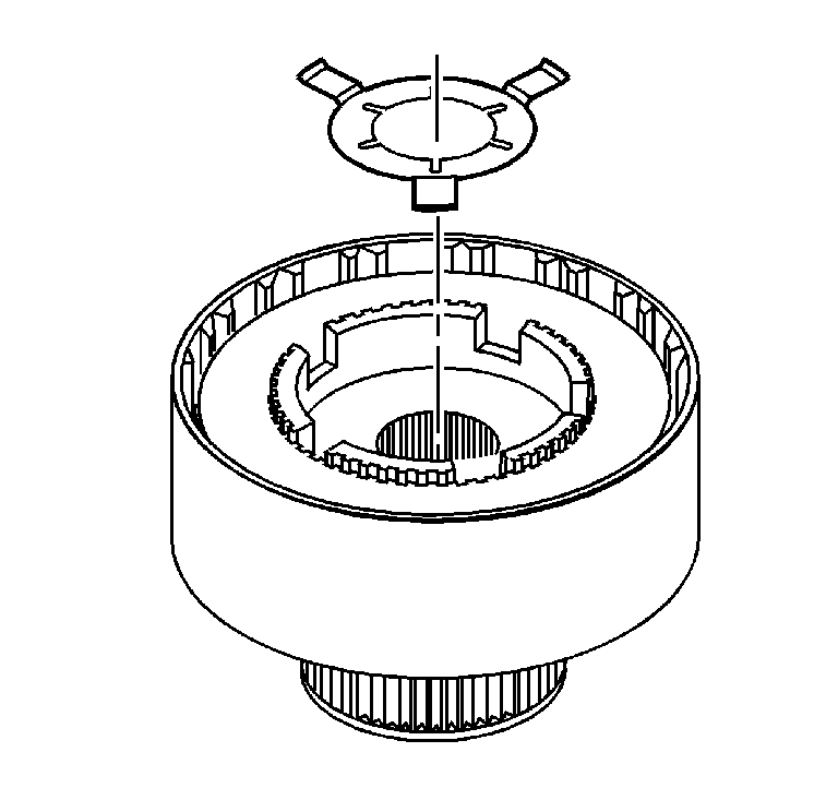
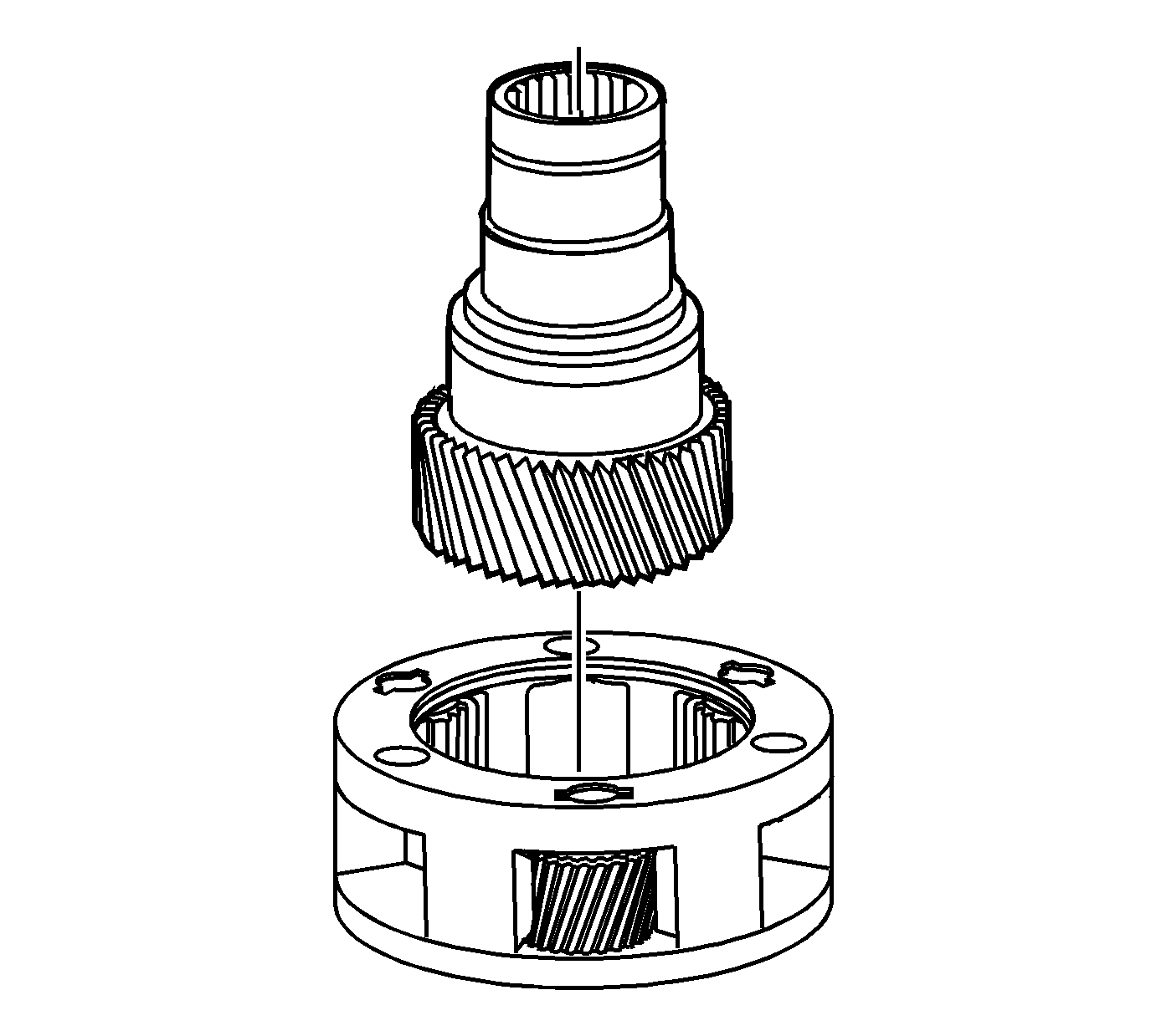
- Remove the high/low planetary carrier.
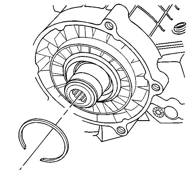
- Remove the front output shaft bearing
retaining ring.
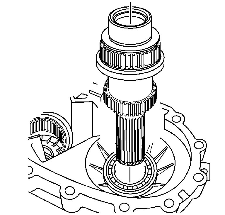
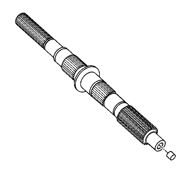
- Remove the front output shaft assembly.
- If damaged, remove the speed sensor
reluctor wheel from the front output shaft using a hydraulic press.
Do not use the speed sensor reluctor wheel again after removal.
- Remove the planetary gear shaft retaining
ring.
- Remove the carrier lock plate.
- Remove the input shaft thrust washer.
- Remove the input gear from the planetary
carrier.

- Remove the thrust washer.
- Inspect the pilot bearing in the input
gear for being faulty. Refer to
Transfer Case Cleaning and Inspection
.
- Remove the pilot bearing from the input gear using a brass drift
and a hammer.
- Remove the input bearing retaining
ring.
- Remove the input bearing.
- Remove the front output shaft front
bearing retainer ring.
- Remove the front output shaft front bearing.
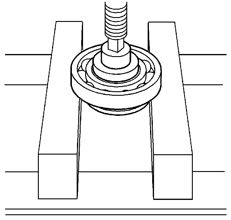
- Inspect the front output shaft rear
bearing for being faulty. Refer to
Transfer Case Cleaning and Inspection
.
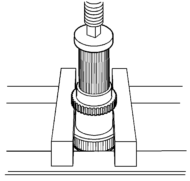
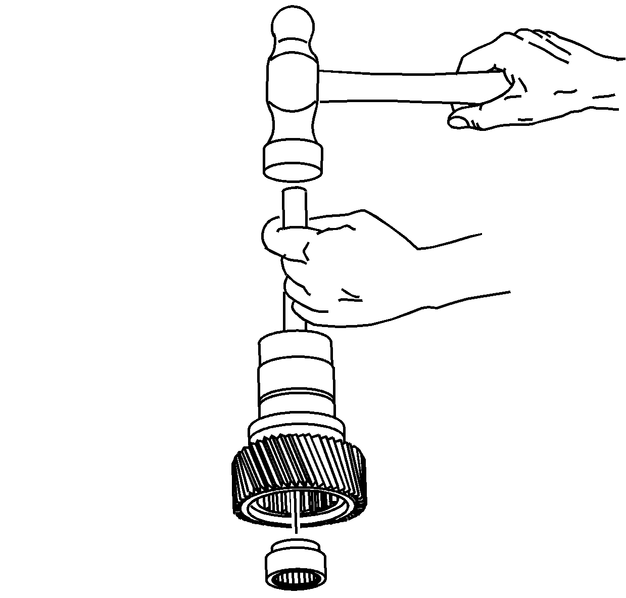
- If the bearing is faulty, remove the bearing using the J 23907
(2) and the J 26941
(1).
- Remove the retaining ring for the
control actuator lever shaft.
- Remove the control actuator lever
shaft.
- Inspect the control actuator lever bearing and seal for being
faulty. Refer to
Transfer Case Cleaning and Inspection
.
- If the bearing is leaking or faulty, remove the bearing from the
case.
